A B-Class Blimp just after takeoff. This type would be the first in a long line of USN patrol blimps. [US National Archives]The B-Class Blimp was a type of non-rigid airship used for training and patrol duty by the United States Navy during, and after the First World War. The type would be the first successful patrol blimp series the Navy would field and would be used until the early 1920s. Its success would prove the effectiveness of coastal patrol airships in the US, and would mark the beginning of a long line of airships operated by the Navy.
A Rocky Start
Two B-Class blimps during a training exercise. Two spherical observation balloons can also be seen. [US National Archives]The First World War was one that saw considerable technological breakthroughs, with many different ideas coming to fruition for the first time or previously small endeavors in weapons now being used in large numbers. Nowhere was this more clear than with aircraft design. Aside from conventional airplanes, lighter-than-air aircraft also saw their first widespread combat use, ranging from the large Zeppelin raids on London, to the observation balloons at the front. Britain would develop their own unique series of non-rigid dirigibles for the sole purpose of patrolling their coastlines and surrounding waters to search for enemy ships and submarines. At first, the Sea Scout class of airship would fill this role, but later the much larger North Sea and Coastal-classes of airship would also be built. These airships would prove very effective in their patrol duties, with some capable of patrolling for hours on end without stopping. The success of these airships would inspire the United States Navy to begin work on their own design in 1915.
An example of a British coastal patrol airship is the Sea-Scout class, which were heavily used during the First World War to patrol the coastline. This type in particular would serve as a basis for the B-class Blimp [Imperial War Musuem]The first of the Navy’s patrol airships would be the DN-1, later considered the A-Class but never officially known as this. The DN-1 was built by the Connecticut Aircraft Company in 1915 using intelligence from German and Austrian non-rigid airship designs of the time. The DN-1 would prove to be a massive failure, having a poor top speed, inadequate lift, and engine troubles which led the type to not be mass produced. Seeking to avoid a repeat of the DN-1, the Navy would begin looking for a more successful design. Their search would lead to the creation of the improved B-Class
The B-Class Blimp
Rear view of the B-1, the first of the B-Class. [US National Archives]The designers at the Bureau of Construction and Repair (Bu. of C&R) would instead look towards the British for inspiration for their improved design over the German/Austrian based DN-1. The result would be the B-Class. Its overall design took heavy inspiration from the British Sea Scout class of airship. The design would be drafted by the Bu. of C&R. There were several expected requirements to the B-class. The airship had to have a top speed of at least 45mph, a 35mph cruising speed with an endurance of 12 hours, communication range of 150 miles, a crew of three, and it had to be able to land on water for emergencies or towing. The design was approved on January 26th by the General Board and a day later by the Navy. An initial order for two B-class blimps was arranged, but this would change on February 4th when a total of 16 were now ordered. This amount was too much for a single company to construct, so instead 5 companies were approached; Goodyear, Goodrich, the Connecticut Aircraft Company, Curtiss and U.S. Rubber. All of these companies, despite being rivals, would work closely together on the construction of the B-class blimps. Three companies would construct the main balloon section themselves, Goodyear, Goodrich and Connecticut. Goodyear was tasked with building B-1 through B-9, Goodrich would build B-10 through B-14 and Connecticut would build B-15 and B-16. Curtiss would focus on building the gondolas of the B-class, which were modified JN-4 Jenny fuselages, as well as building the OXX engines and fins for the craft. U.S. Rubber would supply Connecticut with fabric for the skin. At the start, Curtiss was meant to build three blimps but these would be instead given to Goodrich, as Curtiss had other aircraft projects to focus on. Building military airships was a new endeavor for most of these companies, aside from Connecticut who produced the previously mentioned DN-1. Goodyear had the most experience in terms of production of lighter-than-air aircraft, as they had already produced a number of free and kite balloons for the Navy, and were found to be the most prepared for production of this scale. Thus the first few B-Class were assigned to them.
Design
Underside view of a B-Class and its gondola. [US National Archives]Closeup view of the modified Curtiss JN-4 Jenny fuselages used as the gondola for the B-class. [US National Archives]The B-Class was a blimp designed for patrolling the offshore waters of the American coastline during World War One. The B-Class had a large, teardrop shaped body that was filled with hydrogen. It would be 160 ft (48.8 m) long. The overall volume of the B-classes differed between the companies that built it. At the rear of the body were several fins, two horizontal, one ventral and one dorsal. Each of these, except the dorsal fin, would have control surfaces to move the airship in the desired direction. Hung underneath the body was the gondola. The gondola was a modified Curtiss JN-4 Jenny fuselage with its wings and tail surfaces removed. An additional third seat was added compared to the standard two seats of the JN-4. In the nose of the gondola was a single Curtiss 100 hp OXX-2 engine powering a two-blade wooden propeller. On the two Connecticut B-classes, 100 hp Hall-Scott engines would be used instead. Beneath the gondola, the B-Class originally retained the landing gear from the JN-4, but these were swapped out later for two flotation bags. On the last B-Class built, B-20, a completely new gondola was designed and the craft was much larger than the standard design.
For armament, the B-class would have a Lewis machine gun. For anti-submarine duties, it could carry depth charges or bombs. Additional equipment for the crew included a radio transmitter and receiver, flashlights, a flare pistol with green and red flares, life preservers, rations, drinkable water, maps, a camera, carrier pigeons and signal books.
The B-Class in the War
A B-Class blimp above the Goodyear hangar at Akron. Two Upson kite balloons can be seen in the hangar. [US National Archives]The first B-Class, B-1, would be completed by Goodyear sometime in April/May of 1917. At the time of its creation, Goodyear had been working on building a facility in Akron to house and operate airships, but it was still under construction when B-1 was completed. Thus, Goodyear had to transport the B-1 to the Goodrich facility near Chicago to inflate the craft. The craft was finally inflated and first flown on May 24th, 1917, with Ralph H. Upson at the controls. Upson was an airship engineer and pilot at Goodyear, and a pioneer in the lighter-than-air field, winning an airship race in 1913 and designing his own kite balloons at Goodyear only a few years earlier. He was thoroughly impressed with the first test flights. Upson would take the B-1 up again 5 days after the first flight and would try to fly from Chicago all the way to Akron. His flight started at midnight. Due to an oil leak, he would have to set the craft down at noon, just 10 miles outside of Akron. Despite not making it to his intended destination, Upson had achieved a record for lighter-than-air aircraft travel distance in America. The Navy had doubts surrounding the B-Class after the failure of the DN-1, but with the type already achieving world records on only its second flight, these doubts were quickly amended. The type was already proving its effectiveness even before entering active service. Production of the rest of the 15 B-classes soon commenced and the B-1 was shipped to Pensacola on August 7th, 1917.
B-Class at Akron, Ohio. [US National Archives]As production continued, the various B-Classes would be sent across America to different air stations for duties. These included Naval Air Stations; Pensacola, Cape May, Montauk, Key West, Rockaway, San Diego, and Coco Solo in Panama. B-classes would also be stationed at Hampton for mostly testing purposes. Several improvements of the B-class would occur during its service, improving its top speed from 40mph to 48mph. The B-Class was responsible for patrol and rescue operations off the coastlines of America, and hunting for the dreaded U-Boat. It was found that blimps were much better for patrol duties than airplanes thanks to their long range, extended endurance time, and the ability to hover in midair assisted in spotting enemy warships. The B-Class would perform this duty until the end of the war. If a B-Class encountered a U-Boat, it could deploy depth charges or bombs, or radio in for aerial support from the NAS the aircraft was stationed at. During its service life, at least two B-classes would spot a U-boat and attempt to destroy it, but none would be sunk by the B-Class. The service of the B-class was impressive. It is estimated that the B-classes together patrolled for over 13,600 hours across 400,000 miles. Aside from patrol duties, another impact the B-Class had on the military was its extensive use as a training craft. Several B-classes would be stationed at the aforementioned Goodyear Akron facility solely for the purpose of training. Over 170 aviators would train and be certified on the B-Class, with many headed overseas to operate European dirigibles in service with France and Britain. No B-class blimps were ever sent to Europe.
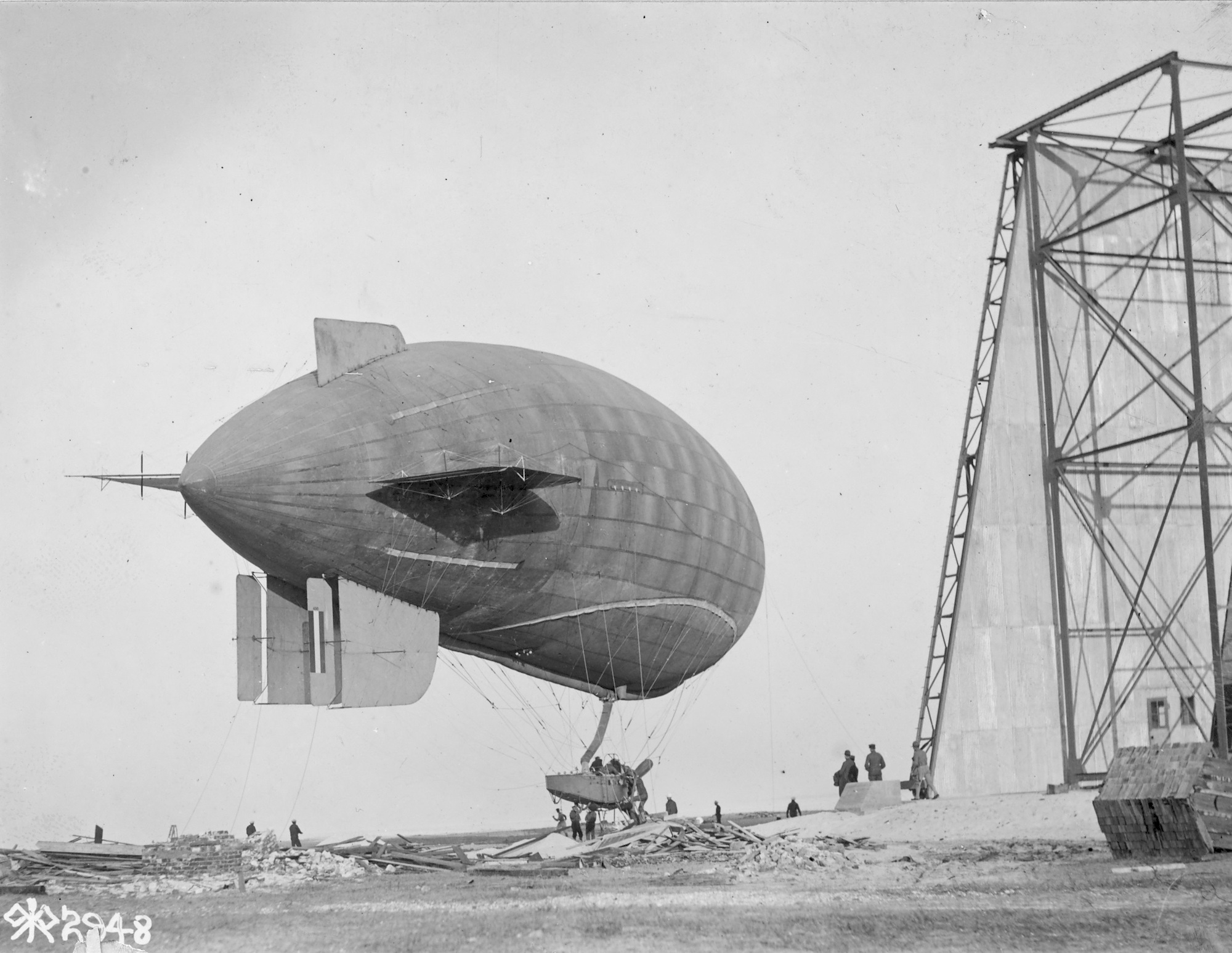
A B-Class preparing for takeoff. [US National Archives]The B-class was not without its accidents. Throughout their service life, many B-class blimps would suffer damage or be completely destroyed while on duty. B-4, B-5, B-6, B-7, B-9, B-12, B-14 and B-16 were all destroyed in accidents before the end of the First World War.
B-Class at Akron Ohio. [US National Archives]Despite its effectiveness, the B-class was found to be lacking as a patrol craft, and the Navy would order a successor design in September of 1918 to amend the shortcomings of the B-class. This was the C-Class (no relation to the aforementioned British Coastal Class which was also known as the C-Class coastal airship) and it took many aspects of the B-Class and improved upon them. The shape of the balloon itself was overall the same, but the C-Class had a much larger gondola that sported two engines instead of one, granting improved speed and maneuverability. The C-Class however wouldn’t be ready before the end of the war, but was instead operated postwar.
The B-Class Postwar
View of a B-class during operations patrolling the Atlantic. This photo was taken from a USN submarine. [US National Archives]The First World War would end on November 11th, 1918, with the B-Class having served well in its duties. Despite the C-Class approaching production, the B-Classes still in service would continue to operate, however a few were stricken off to reduce the fleet size. Three B-Class blimps would be rebuilt reusing the envelopes from previously damaged blimps. These would be B-17, B-18 and B-19. B-17 is known to have reused the envelope from B-1, which was damaged on June 17th, 1920. B-18 likely used the envelope from B-13. Details on B-19 are lacking. It is known that these three blimps were constructed sometime in 1920. The final B-class built would be the B-20. Details are also sparse on this craft but it is known to have had a completely unique gondola design and was much larger than the standard B-Class. In the bureau number list, B-20 is listed as being before the aforementioned rebuilt gondolas. Interestingly, these B-classes were all built after not only the introduction of the C-Class, but even after its successor, the D-Class. All postwar built B-classes were constructed by Goodyear. The remaining B-classes continued to serve into the early 1920s, with many of them being scrapped due to accidents or deterioration with age. By 1924, three B-classes remained, B-3, B-8 and B-15. B-8 was heavily deteriorated but B-3 and B-15 were still in operational condition. By this point however, the B-class was heavily outdated, and with its services no longer required, the last 3 were surveyed and scrapped in 1924. The B-class actually wound up being in service longer than its successor, as the few remaining C-Classes had been scrapped in 1922.
Conclusion
A B-Class above the Naval Air Station at Key West, Florida. [US National Archives]The B-Class was an important achievement to the United States Navy, proving the effectiveness of patrol airships and paving the way for a long line of succeeding designs. The B-Class would train aviators that would go on to protect allied countries in foreign built dirigibles, and would protect the American coasts from U-Boats. B-Class blimps would serve the Navy well past its expiration date, even surpassing its own successor. The Navy’s LTA airship fleet began with the humble B-Class, and would continue for almost five decades later.
One of the early B-Classes built by Goodrich. Notice the double ventral fins. [US National Archives]
Service List
B-1: The first in the B-Class series, B-1 would survive the war. On June 17th, 1920, B-1 would be damaged at Pensacola and would be stricken off. The gas bag was later reused on B-17.
B-2: B-2 would survive the war and would be stationed at Key West. On February 28th, 1919, B-2 would completely wreck.
B-3: B-3 would survive the war and continue to serve until it was surveyed in 1924. The ship was damaged several times but was fully repaired each time.
B-4: Stationed at Hampton NAS for testing. On August 8th, 1918 the craft was damaged and stricken. The blimp was salvaged for spare parts.
B-5: Stationed at Akron. While on maneuvers, it would be completely destroyed on November 21st, 1917.
B-6: Service details are lacking, stricken from the Navy on September 7th, 1918.
B-7: Stricken June 8th, 1918.
B-8: Survived the war and served until March 19th, 1924, where it was surveyed due to deterioration.
B-9: Stationed at Key West. On April 21st, 1919 would completely wreck due to engine failure.
B-10: Stationed at Cape May. During maneuvers on December 7th, 1918, it would be heavily damaged. The craft was sent back to Goodrich but the repairs were considered too expensive and B-10 was scrapped. The envelope was torn up and distributed to other air stations to serve as repair materials on other blimps.
B-11: Shipped to Pensacola, service ended on August 15th, 1919. Service unknown.
B-12: B-12 wrecked while on patrol on July 26th, 1918.
B-13: Damaged numerous times during service at Montauk Naval Air Station. Envelope appears to have been salvaged and later reused but on what aircraft is unknown, possibly B-18. It was recommended to be stricken off at two different stations in 1919, at Montauk and Rockaway.
B-14: Wrecked July 20th, 1918 at Montauk(?).
B-15: Served at Pensacola through the war and after. Was finally surveyed on April 22nd, 1924.
B-16: Official report is spotty but on June 17th, 1918, the craft was destroyed.
B-17: Rebuilt gondola, reused the envelope from B-1, service unknown.
B-18: Rebuilt gondola, envelope possibly from B-13. Service unknown.
B-19: Rebuilt gondola, service unknown.
B-20: Last B-class. Built in 1920. Completely new gondola design. Service unknown.
Variants
Goodyear/Goodrich B-Class (1 through 14) – B-classes built by Goodyear/Goodrich would use Curtiss OXX-2 engines. The first few of these had double fins but these were later changed to a single fin.
Connecticut B-Class (15 & 16) – The two B-Classes built by Connecticut would use Hall-Scott engines. These two appear to have the double fins as well. Unknown if any of these were later changed.
B-20 – The last B-class produced. It would have a unique gondola design.
Operators
United States of America – The 20 B-classes built would be operated by the United States Navy for patrol and training purposes until 1924.
B-Class (Goodyear) Specifications
Length
160 ft / 48.8 m
Diameter
31.5 ft / 9.6 m
Volume
(Varies between companies)
77,000 ft³ / 2180.4 m³
Engine
1x 100 hp ( 73kW ) Curtiss OXX-2 8-cylinder engine
Kingdom of Hungary (1938)
Reconnaissance Aircraft & Light Bomber – 128 Built
The Weiss Manfrédfrom WM 21 two-seat reconnaissance aircraft. [lasegundaguerra.com]The Hungarian Aviation industry was rather small in scope in comparison to many in Europe. Regardless, it managed to introduce a number of domestic development projects. One of these was the Weiss Manfréd from WM 21, a two-seat reconnaissance aircraft of which some 128 were produced during the Second World War.
History
In the years after the First World War, Hungary was strictly forbidden from developing combat aircraft. To overcome this limitation, the Hungarians did what the Germans did and began developing a civil aircraft industry to help gain valuable experience in aircraft design. One of these companies that would emerge during the late 1920s was Weiss Manfréd, from Csepel near Budapest. In 1928 this company began working on the design and construction of gliders and engines.
Due to an initial lack of funds, the Hungarian Air Force was forced to rely on foreign aircraft that were bought in relatively small numbers. For example, by 1937 Hungarians had only around 255 operational aircraft. To help gain more experience, Weiss Manfrédfrom began producing Fokker F.VIII and C.V aircraft under license. When sufficient funds and experience were gained, Weiss Manfrédfrom engineers in 1935 began working on a new reconnaissance biplane design. They decided on a simple design, reusing some components that were already in production, and it would be a further development of the already produced WM 16 model, which was heavily based on the D version of the Fokker C.V.
The WM 21 predecessor was the WM 16 model which in turn was based on the C.V aircraft. [Wiki]When the prototype of the new short-range reconnaissance aircraft, WM 21 “Sólyom” (Falcon) was completed, it was presented to Hungarian Air Force officials, who were generally satisfied with its performance and gave an order for some 36 WM 21 in 1938. At that time, massive funds were being allocated to the development of the aircraft industry. In addition, Hungarian Air Force officials wanted to decentralize aircraft production. For this reason, the WM 21 was to be built by various other companies, including twelve to be built by MÁVAG and MWG
It was estimated that the production would commence during April and March 1939. It took longer to do so, with the first aircraft being available at the end of 1939. While the aircraft was slowly put into production, the Hungarian Air Force asked for more aircraft to be built.
In Combat
The WM 21 was primarily designed as a reconnaissance aircraft but due to a general lack of other aircraft types, it would be adopted for other roles. Its first combat use was during the so-called Transylvanian Crisis. Namely, in June 1940 Hungarian government demanded that Romania return the Transylvania region to them. Since it looked like war was coming, Hungarian Air Force began relocating its aircraft close to the Romanian border. Thanks to the commencement of negotiations, no war broke out. But by late August the Hungarians ordered a complete mobilization as the negotiation led nowhere.
While primarily intended to be used as a reconnaissance airfare it would be also used in other roles even as a light bomber. [lasegundaguerra.com]Germany did not want to lose its vital Romanian oil supply and forced both countries to begin new negotiations under German and Italian supervision. While the negotiations were underway, some smaller air skirmishes occurred. On the 27th of August, a Romanian He 112 attacked a Hungarian Ca 135 aircraft, which was heavily damaged and one crew member was killed. The following day a WM-21 piloted by Captain János Gyenesin, dropped bombs on the Romain Szatmárnémeti airfield in retaliation for the lost airman. On its way back it crash-landed, damaging the aircraft. In the end, Hungary emerged as the victor, gaining large territorial concessions over the Romanians.
When the April War broke out on the 6th of April 1941, between the Kingdom of Yugoslavia and the Axis, the Hungarians joined the offensive. They employed their 1st Air Brigade which had some 60 aircraft. By the 17th of April, the war was over, and the Hungarian Air Force had lost 6 aircraft including one WM 21.
A colorized picture of the WM 21 rearview. [all-aero.com]On the 26th of June 1941, the Hungarian town of Kassa was bombed by three aircraft. The circumstance of this incident is not clear even to this day, but the Hungarian government asserted that it was a Soviet attack. The decision was made to declare war on the Soviet Union as a response. For the initial operation in the war against the Soviets, the Hungarian Air Force allocated 25 bombers (Ju 86 and Ca 135), 18 CR 42 fighters, and the 8th and 10th reconnaissance squadrons each equipped with 9 WM 21.
By 1942 most WM 21’s were allocated for use by training schools and as liaisons. Some would be used in later years for anti-partisan operations. By the end of the war, some WM 21 pilots managed to reach Austria where they hoped to surrender to the Western Allies.
Technical Characteristics
The WM 21 was a mixed-construction, biplane aircraft, designed to fulfill multiple roles. The fuselage and the wings were of metal construction which was covered in fabric. The lower and the upper wings were connected with each other by one “N” shaped metal strut on each side. In addition, there were two “V” shaped metal brackets that were connected with the fuselage and the upper wing. Lastly, there were two larger metal struts on each side that connected the landing gears to the top wing.
The WM 21 was a biplane two-seater aircraft. The lower and upper wings were held in place by various smaller metal bars, connecting them to each other and to the fuselage. [all-aero.com]The landing gear consisted of two fixed road wheels and a rear-positioned landing skid. Partly-covered front wheels were connected to the aircraft fuselage by three large metal bins.
Initially, the WM 21 was powered by an 870 hp Weiss WM K-14A radial piston engine. With this engine, the WM 21 could reach a maximum speed of 320 km/h. Later produced aircraft were equipped with a stronger 1,000 hp WM K-14B engine. With this engine, the maximum speed was increased to 380 km/h.
The pilot and the observer/machine gunner were placed in two separate open cockpits, the front for the pilot, and the rear for the observer. For better downward visibility the observer was provided with two fairly large glass panels, placed just under him on both fuselage sides.
Side view of the WM 21. Note the small glass panel located under the observer cockpit. [lasegundaguerra.com]The WM 21 was armed with two forward-firing 7.92 mm Gebauer machine guns. One additional defensive machine gun was placed in a flexible mount which was installed in the rear cockpit. Additionally, the offensive capabilities of the aircraft could be increased by adding bombs. The bomb bay was placed between the two crew members. To release the bomb the crews would use a release mechanism. The bomb load could consist either of 12 10kg anti-personnel bombs, or 60 1kg incendiary bombs. Later versions increased the bomb load to around 300 kg.
To the rear an additional 7.92 mm Gebauer machine gun was placed in a rotating mount for self-defense. [airwar.ru]
Production and Modifications
The WM 21 was produced in four small series. When the production ended in 1942 some 128 aircraft would be constructed. While designed by Manfred Weiss, this factory produced only 25 aircraft. The MAVAG produced 43 with the 60 being built by MWG. Due to the relatively low production numbers, only one modification of the original aircraft was ever made:
WM 21A – Powered with an 870 hp Weiss WM K-14A engine,
WM 21B – Slightly improved version powered by 1.000 hp WM K-14B engine
Some 128 WM 21 would be built by 1942 when the production ended. [all-aero.com]
Conclusion
The WM 21 was a Hungarian reconnaissance aircraft that would see service on several different fronts. While initially used in its intended role, it quickly became obsolete and was allocated to secondary missions, as a training aircraft or for liaison missions. Due to a lack of adequate aircraft, some WM 21would even see service as combat aircraft against Partisans forces, mostly in the Soviet Union.
WM-21A Specifications
Wingspan
12.9 m / 42 ft 4 in
Length
9.65 m / 31 ft 8 in
Height
3.5 m / 11 ft 5 in
Wing Area
32.75 m² / 352.53 ft²
Engine
One 870 hp (649 kW) Weiss WM K-14A radial piston engine
Empty Weight
2,450 kg / 5,400 lb
Maximum Takeoff Weight
7,606 kg / 3,450 lb
Maximum Speed
320 km/h / 200 mph
Cruising Speed
275 km/h / 170 mph
Range
750 km / 466 mi
Maximum Service Ceiling
8,000m / 26,245 ft
Climb speed
Climb to 6,000 m (19,700 ft) in 7 minutes and 30 seconds
Crew
One pilot
Armament
Three 7.92mm machine guns
Total bomb load of some 100-300kg
Gallery
Weiss Manfred WM 21 “Sólyom”
Credits
Written by: Marko P.
Edited by:
Illustrations by Carpaticus
Sources:
D. Monday (1984, 2006) The Hamlyn Concise Guide To Axis Aircraft Of World War II, Aerospace Publishing Ltd.
G. Sarhidai, G. Punka, and V. Kozlik (1996) Hungarian Eagles, Hikoki Publication
G. Punka (1994) Hungarian Air Force, Squadron Publication
S. Renner. (2016) Broken Wings The Hungarian Air Force, 1918-45, Indiana University Press
USA (1915) Observation & Training Balloon – 10+ Built
The Kite Balloon operated by the Navy at Pensacola. This particular balloon is based off the first patent. [Naval History and Heritage Command]The Upson Kite Balloons, also known as Goodyear Kite Balloons or simply Upson Balloons, were a series of three observation balloon designs by Ralph Hazlett Upson to improve upon the design of the German Parseval-Sigsfeld Drachenballon. Two of the designs would be built by the Goodyear Corporation and sent to various balloon training schools and even operate off of ships, but the type was found to not offer much improvement over the Drachenballon, and the much more advanced Caquot balloon which would be introduced only a year after the Upson balloons were built, making the type null. A 3rd design would be patented but wouldn’t be built.
Ralph H. Upson and the Parseval-Sigsfeld Drachenballon
R.H Upson outside of the Goodyear Hangar in Akron, 1917 [US National Archives]Ralph H. Upson was a pioneer in balloon and airship development in America in the early 1900s. In 1913, using his own airship design, he would win the International Balloon Race. Upson was an employee of the aeronautics division of the Goodyear Rubber and Tire Corporation where he was a pilot and engineer on the various lighter-than-air projects the company had been working on. Upson would mainly work at the Goodyear plant in Akron, Ohio. In 1914, the company began building observation kite balloons for the US Army to use in their balloon divisions. The main type of kite balloon in use was the German designed Parseval-Sigsfeld Drachenballon. The Drachenballon was designed over a decade before in 1898 and was a replacement for the spherical observation balloons of the previous century, as the latter was found to be almost unusable when in windy conditions. The Parseval-Sigsfeld design was built in such a way it would face towards the wind thanks to a large, air-inflated steering bag at the rear of the balloon. Thus it was named Drachenballon, or “kite balloon”. America would build and operate several Drachenballons before their entrance into the First World War.
An example of a German-operated Parseval-Sigsfeld Drachenballon. [Waffen Arsenal 149]Upson would begin designing an improvement over the Drachenballon in 1915. Using the knowledge he learned from working on airships, he’d incorporate a number of features that would hopefully improve the overall stability of the German balloon. Two designs would be created at first in late 1915, with the patents on these designs being filed on June 20th, 1916.
Kite Balloon Design 1: Back to Basics
Kite Balloon Design 1 in the patent. The Navy-operated balloon in Pensacola is of this type. [Google Patents]An Upson balloon being inflated at Pensacola. [State Archives of Florida]The first of these designs was essentially a heavily modified Drachenballon. Its overall appearance and construction was the same. The balloon consisted of a large cylindrical gas bag. In the nose was a valve that regulates the pressure and gas and can be opened for release automatically or manually. On the underside was a neck to which the hydrogen gas was filled from. The Upson’s balloon’s neck was much longer than the neck on the Drachenballon. On the sides of the balloon were two stabilizing fins. On the Drachenballon, these fins are rectangular in shape. On Upson’s design, these would be triangular in shape and would sag down in flight. According to Upson, the rectangular fins of the Drachenballon only offered stabilization horizontally, while his fins would also prevent yaw and pitch movement. Internally at the rear was a large air bag to keep the balloon’s shape stable if the balloon isn’t fully inflated and keep the balloon at a 30-40 degree angle while in the air. The main difference between Design 1 and the Drachen involved the aft section of the balloon. On the standard Drachen is a large air-inflated steering bag that would keep the aircraft stable. On Upson’s design, the balloon would instead slightly taper at the rear. The steering bag would be removed altogether, instead replaced with a large keel-shaped bag. Upson’s thinking behind this change was that the steering bag wasn’t aerodynamic and instead opted for the more sleek keel bag over it, improving airflow. The keel bag and the ballonet were both connected via an intake at the tip of the keel. In addition, the tail of the balloon was connected to the keel, to which several tail cups were placed not only for stabilizing but to keep the keel straight. The tail cups were placed much closer to the balloon than on the Drachenballon. The rubber balloon girdle also differed from the Drachenballon slightly,as it wouldn’t be uniform all around the balloon, instead dipping slightly down near the front. The balloon would be made of rubberized and non rubberized fabric and filled with Hydrogen.
An Upson Kite Balloon in flight [US National Archives]One of the Upson balloons preparing for flight at the Goodyear Plant in Akron. The other is visible in background hangar. The USAAC roundel is barely visible on the underside. [US National Archives]BC-3 moored to the USS Huntington. [Wikipedia]The Upson balloon BC-3 operating off of the USS Huntington. [navsource.org]The Navy Design 1 balloon operating from the USS Oklahoma [NavalHistory.org]Several Design 1 balloons are known to be built. The first would be built at the Goodyear plant in Akron in late 1915. While testing was going on in November, it was observed by officials from the Navy who were looking to increase the USN’s LTA (Lighter Than Air) fleet. The Design 1 balloon was accepted into service for the Navy on December 22th and shipped to the Pensacola Naval Air Station in Florida. The balloon would finally arrive on April 5th, 1916, along with a handful of Goodyear employees who helped with training. Only two days after arriving, the balloon would be damaged from heavy winds and would break from its mooring. The balloon would be repaired shortly after. Once repaired, the balloon was stationed aboard the USS Nevada and USS Oklahoma for testing. The balloon was found to offer increased visibility, but there were a number of reasons why using it from a battleship was a bad idea. The balloon was a very easy target, explosive due to its hydrogen gas (which often leaked), and gave away the position of the battleship. Inflating the balloon was also slower than what was expected. In some cases the balloon itself affected the maneuverability of the ship. It was noted that many of these issues could be fixed in the future, but no changes to this balloon are known to have occurred. Despite not performing well aboard a ship, the Navy continued to use the Design 1 balloon at the Pensacola Air Station for testing and training. Two more balloons were ordered, with the designations of CB-2 and CB-3 for the Navy. Both of these balloons are known to have been tested on the USS Huntington for evaluation. Even further on, the balloon CB-4 was ordered. It is unknown what type of balloon this was, whether Design 1 or 2.
Photo of a Design 1 balloon at Fort Omaha, Nebraska [Museum of the United States Air Force]Aside from the Navy, the United States Army Air Service would also use two Design 1 balloons. One is known to be used for testing purposes. This balloon in particular has an extra set of stabilizing fins located a few feet in front of the regular stabilizing fins. Aside from testing, its service history is unknown. All that is known about it is comes from a US Army report evaluating it and a few photos to go along with said report. The report was very appraising of the type over the standard Drachenballon. The second known USAAS Design 1 balloon had an interesting history. From 1910 to 1919, the United States was in an armed conflict with Mexico on its border, known as the Mexican Border War. During this, many Army units would be stationed along the border. An Ohio National Guard Artillery unit was deployed along the border and stationed at El Paso, Texas in 1916. Accompanying the division was a Design 1 kite balloon gifted to the division by Goodyear. Along with the balloon, Ralph H. Upson himself would be assigned to assist in operations and training personnel for the balloon. The balloon would be used to observe Mexican forces moving near the border. Aside from its service in the War, the fate of this balloon is unknown. It was, however, the first observation balloon operated by the National Guard and is known to have been built shortly after the first Design 1 balloon.
Kite Balloon Design 2: All New
Design 2. This particular type would see several produced. [Google Patents]The second design was also included on the June 20th patent and would greatly differ from the standard Drachenballon. In fact the only two similarities between the two designs would be their overall layout, other than this, the two designs are greatly different. The overall shape wasn’t cylindrical, but instead more round. Carrying over from Design 1 are Upson’s unique side fins, keel bag, and extended neck. The evacuation valve in the nose was moved upward and is near the top of the nose instead of directly frontally. Instead of having a balloon girdle, the ropes connecting the mooring line and basket were instead connected to individual rubber connection points around the main body of the aircraft. The pattern of the connection points is the same shape as the girdle on Design 1, with it arching down towards the front. The aircraft would also be stabilized by an internal ballonet. Specifications for this balloon do exist. It was to have an internal volume of 25,000 ft³ (707.9 m³). The maximum service ceiling would be 6000ft (1828.8 m). On the underside of two of the balloons, a United States Army Air Corps roundel is printed.
Goodyear would build at least four of this balloon type for training and testing. Two of these would be sent to the Fort Omaha balloon school in late 1916. Here they would be used in the training of the balloon corps alongside Drachenballons and spherical balloons. Two more of this type were photographed at the Goodyear Akron plant during a maneuver with other lighter-than-air aircraft. There is a chance these two aircraft are the same as the ones in Omaha but their overall appearance differs slightly. On one of the balloons is a box-like structure located at the side of the balloon. These are not present in the patent or on the other balloons and their purpose is unknown. It is possible these were some form of additional stabilizers but it is not confirmed. This type appears to be exclusively used by the USAAS.
The same excercise as before at Akron with all balloons now airborne. What appears to be a B-Class Blimp is in the background as well. [US National Archives]On September 23rd, 1916, two pilots; Carl K. Wollam and Charlie Roth, were interested in one of the Goodyear Design 2 balloons then stationed at Dayton, Ohio. Both men, who were aircraft pilots, wanted to see how well the Upson balloon would do in untethered flight. It should be noted neither man had piloted a balloon before. The two would go up in the balloon, and then cut the cable. The balloon would go to an altitude between 5000 and 6000 ft (1524 and 1828.8 m) for a distance of over 120 miles (321.9 kilometers). The flight would last over 3 hours. The two wanted to head to Akron to land but their attempt failed and they were thrown off course for 70 miles (112.6 kilometers), finally landing in a farm near Circleville, Ohio. This would be the first free flight of a kite balloon in the US. Despite not being designed for this flight, the pilots said the balloon was hard to control, but overall performed well for the task.
Kite Balloon Design 3: Double Trouble
Side view of Design 3. This design was essentially two Design 2 kite balloon bodies sewn together. [Google Patents]Frontal view of Design 3. [Google Patents]The last of the Upson balloon designs was not included in the first patent document, instead being patented a few months later on November 9th, 1916. This 3rd balloon design differed greatly from most balloon designs of that era. Design 3 essentially was two Design 2 balloons sewn together side by side. Upson would call it a “Composite Balloon” in the patent. Each side of the balloon would have design features from Design 2. At the rear interior of the gas bag was an air-fed ballonet to keep the overall shape of the balloons intact when not fully inflated. The overall shape of the gas bag was changed, with Upson specifically mentioning that the bottom was flattened out to aid in aerodynamics. In each nose was an emergency gas escape valve to regulate the gas. On each side was one of Upson’s triangular stabilizing wings and at the rear was the keel bag. Instead of the tail cups that were common for kite balloons and used with the previous two designs, Upson would design a completely new tail stabilizing device. A large concave strip would connect to two ropes. Each rope would connect to an end of one of the gas bags. The strip would catch the wind like a parasail, stabilizing the balloon. Upson’s overall choice for the double body design was to greatly increase the stability and maximum height over contemporary balloon designs, with the idea that another body would assist in that regard considerably. The ropes connecting the basket were equally distributed to each of the balloon bags.
Despite Upson claiming it to be superior over his previous two designs, no composite balloon was ever built.
Too Late: The Caquot Arrives.
Two Upson Balloons are part of an exercise at the Akron Goodyear Plant, along with two Caquot Balloons. The photograph label incorrectly states all four balloons are Caquot R Types. [US National Archives]From reports, the improvements done by Upson over the Drachenballon design did positively impact its design, making it much more stable in strong winds. A Design 1 balloon is known to have remained stable in 45mph winds. Despite the positive reception, there are still mentions that the Upson balloons design wasn’t perfect and it suffered still in terms of total stabilization compared to newer the newe balloons on the horizon, but overall it performed better than the Drachenballon in this regard. Upson’s balloon designs would have only just started their testing when the French officer, Albert Caquot, would create his superior balloon design in the later months of 1916. The design was created to completely fix the flaws of the Drachenballon. To fix the stability issues, two more air-inflated bags were placed at the rear of the balloon, totalling 3 stabilizers spaced 120 degrees apart from each other. The type was found to be completely superior over the Drachenballon and it quickly began replacing allied, and eventually German Drachenballons. Goodyear would later license build Caquot type balloons in 1918, for use by the American Balloon Corps. By their entrance in World War One, the US would only use Caquot types in combat operations in Europe. No further Upson balloons were built after 1917. Despite this, the two Design 2 balloons stationed at the Fort Omaha balloon school would continue to be used for training purposes until the closure of the school in 1919. It is unknown what fate befell the Navy operated kite balloons.
The Design 1 Balloon in operation at El Paso, Texas during the Mexican Border War. [texashistory.unt.edu]An Upson Balloon at the Fort Omaha Balloon School. [US National Archives]Due to a lack of information regarding these balloons, it is entirely possible, and extremely more than likely that more than the known amount of Upson balloons were built, but records and photos concerning the production of Design 1 and 2 types are severely lacking.
Upson would continue his work in the field of lighter-than-air aviation, working for Goodyear into the 1920s until he would leave the company to pursue his own vision of lighter-than-air aircraft. He would create the Aircraft Development Corporation, where he would design and build the metal-skinned airship ZMC-2 for the Navy. Upson would continue in the aviation industry all the way through the Second World War and into the 1950s.
A B-Class Blimp flies over the Goodyear hangar in Akron. One of the Upsons is being either taken in or out of storage. The second is visible in the hangar. [US National Archives]
Variants
*Note, the “Design” names are not the official designation, but named so here for simplicity.
Design 1– Heavily modified Drachenballon with improvements made by Upson. These include larger side stabilizers, the removal of the steering bag and the new keel bag for wind stabilizing. Five are confirmed to be built, with a possible 6th.
Design 2 – Completely original design that took the improvements from Design 1 and put them on a new design. Design 2 had a much more rounder body over Design 1. Four are known to have been built.
Design 3 – Composite balloon. Consisted of essentially two Design 2s sewn together. Reused all of the aforementioned modified side fins and keel bags. Would have a unique tail stabilizing parachute.
Operators
United States of America – The Upson types built were used by the balloon corps of the United States Army Air Corps and Navy.
Upson Kite Balloon Design 1 Specifications
Length
82 ft / 25 m
Diameter
22 ft / 6.7 m
Volumes
25,000 ft³ (707.9 m³)
Gas Type
Hydrogen
Material
Rubber-infused and non-infused cotton fabric
Maximum Service Ceiling
6000 ft / 1828.8 m
Crew
2 Observers
Equipment
Telephone
Upson Kite Balloon Design 2 Specifications
Volumes
25,000 ft³ (707.9 m³)
Gas Type
Hydrogen
Material
Rubber-infused and non-infused cotton fabric
Maximum Service Ceiling
6000 ft / 1828.8 m
Crew
2 Observers
Equipment
Telephone
Gallery
Illustration of Upson Balloon Design 1 by Ed Jackson
Independent State of Croatia (1942)
Fighter – 16 Operated
In NDH service the Fiat G.50 did not receive any modifications, with the original Italian camouflage remaining. The only change was the addition of Croatian military markings and new identification numbers. [Wiki]Following the creation of the Nezavisna Država Hrvatska (Independent State of Croatia), its Air Force was plagued with many problems from the start, including a lack of modern aircraft. While generally heavily reliant on the Germans to provide them with better equipment, they were unwilling to secure any deliveries of aircraft. To resolve this issue the NDH’s Air Force officials managed to persuade Italy to sell them 10 Fiat G.50bis fighters, which remained in use up to 1945.
A Brief History of the NDH
Following the end of the First World War, Kraljevina Srba Hrvata i Slovenaca (The Kingdom of Serbs, Croats, and Slovenes – SHS) was formed in December of 1918 with the aim of uniting all Southern Slavs. This new state was, at least in theory, based on the principles of equality for these three nationalities. In reality, this Kingdom was a politically and ethically divided country. During the 1920s, there were huge political disagreements between the major parties which brought about questions regarding the continued existence of the Kingdom of SHS. This division was especially noted between the Serbian and Croatian politicians, which ultimately culminated in the assassination of several Croatian Peasant Party members, including the leader, Stjepan Radić, by a Serbian Politician in 1928.
On 6th of January, 1929, King Aleksandar Karađorđević, in an attempt to avoid the incoming political crisis, led the country into a dictatorship by abolishing parliament. He also introduced a number of political changes, including changing the name of the country to Kraljevina Jugoslavija (Kingdom of Yugoslavia.) This essentially did not resolve any of the existing problems, as inter-ethnic tensions persisted. During the early 1930s, the first mentions of Croatian Ustaše (the precise meaning is unknown, but could be roughly translated as insurgent) ultranationalist revolutionary organizations began to appear in Yugoslavia. Their main aim was the liberation of the Croatian people from Yugoslavia, by all means necessary, even by force. One of the most prominent figures of this organization was Ante Pavelić.
Ante Pavelić was a high-ranking Ustaša member from the start, and later de facto leader of the NDH. [Wiki]The Ustaše organization participated in the assassination of the Yugoslav King, Alexander Karađorđević, in Marseille in 1934. This assassination backfired to some extent for the Ustaše organization. Not only did it not lead to the collapse of Yugoslavia, but relations with Italy also improved under the Regent Prince Pavle Karađorđević in the following years. This led the Italian authorities to effectively end their support for the Ustaše and even arrested some of its members, including Pavelić.
After years of inactivity, the Ustaše benefited when the Yugoslavian government, which supported the Axis, was overthrown by pro-Allied officers in a military coup at the end of March 1941. Adolf Hitler almost immediately issued an order that Yugoslavia should be occupied. The Italians, preparing to join the war against Yugoslavia, began to support the Croatian Ustaše movement once again. With the collapse of the later Kingdom of Yugoslavia during the Axis invasion after the short April War of 1941, Croatia, with German aid, was finally able to declare independence, albeit becoming a fascist puppet state. Ante Pavelić was chosen as the leader of this puppet state. Officially, the NDH was announced on 10th April 1941. The new state received a significant territorial expansion by annexing most of western Yugoslavia, including Bosnia, parts of Serbia, and Montenegro. The Adriatic coast, while nominally part of the NDH, was actually controlled by the Italians until 1943.
The NDH took over a large portion of the Yugoslavian territories. [Wiki]
Formation of the NDH Air Force
Following the collapse of the Kingdom of Yugoslavia, NDH began organizing its newly-created armed forces. Its Air Force was created on the 19th of April, 1941. The leadership of the new Air Force was given to Colonel Vladimir Kren. Immediately, work began on creating adequate structural organization, acquiring manpower, and procuring equipment. Initially, plans for arming this Air Force were ambitious, including some 140 modern aircraft, such as the Ju 88 and Me 109. Its officials were quite disappointed as Germans were not willing to provide these. Instead, the NDH officials had to make do with the leftovers of the Former Royal Yugoslav Air Force, which was in German hands. NDH officials made a request that included over 50 aircraft. The Germans once again disappointed them and gave NDH only those aircraft that were mostly obsolete, while transferring the better aircraft, like the Hurricanes, to Romania instead. The only other way to acquire more capable aircraft was to ask the Italians. This is what the NDH Air Force officials did in early 1942.
The NDH Air Force was initially equipped with surviving Yugoslavian aircraft, in this case, Rogožarski P.V.T. [The Croatian Air Force In The Second World War]
The Fiat G.50 brief history
During the thirties, the Italian Ministry of Aviation (Ministero dell Aeronautica) was interested in adopting a new, all-metal monoplane fighter and ground-attack aircraft for the Italian Air Force. In April of 1935, engineer Giuseppe Gabrielli began working on a new low-wing, all-metal plane named G.50. On 28th September 1935, Gabrielli submitted his project to the Ministry of Aviation. Military officials were impressed by the design and asked him to proceed with its work. As Fiat’s production capacities were overburdened, work on this new project was instead moved to the CMASA works at Marina di Pisa, part of Fiat since 1931. Giuseppe Gabrielli was finishing his last drawings and the list of needed materials and equipment in June 1936.
The prototype was finally ready at the beginning of 1937 and was transported to the city of Turin for further testing. This prototype, under registration number MM 334, made its first test flight on 26th February 1937. Once accepted for service, the Fiat G.50 would become the first Italian all-metal fighter. Between 1938 to 1943 some 774 to 791 of all versions of the G. 50 would be built. These saw combat service starting from the Spanish Civil War, until 1943 when the few surviving aircraft were reassigned to secondary roles.
A G.50 flying together with a German Bf-110, possibly during the Battle of Britain. [Wiki]
In Yugoslavia
The Fiat G. 50 participated during the short Invasion of Yugoslavia in April 1941. Two fighter groups, the 24th, and 154th, which had 53 G.50 fighters in total were allocated for this operation. They mostly performed a few escort missions. Due to the rapid collapse of Yugoslavia’s Royal Army, these saw limited actual combat use, if any. Afterward, the Fiat G.50 was allocated to other fronts. During 1942 and 1943, limited numbers of these aircraft were used for ground attack operations against the Yugoslavian Partisans.
In NDH’s Hands
By 1942, most of the available aircraft in NDH Air Force were in poor condition, mostly due to a general lack of spare parts. NDH Army officials approached Italy with a request for 9 improved Fiat G.50 and one two-seater version. The Fiat G.50bis were slightly modified versions that had an increased fuel load, a redesigned rear fuselage and vertical stabilizer, better glazing of the cockpit, and other minor changes. But in essence, it did not offer many improvements compared to the basic version. The G.50 B bipost (two-seater) was a modified G.50 fighter version with a new cockpit and dual controls for a pilot and trainer. The front section of the cockpit was fully enclosed, in contrast with the rear which was open. The main armament was removed on the G.50 B. This version was very successful, as it was easy to build and offered almost the same flying performance as the single-seat version.
The Fiat G.50 B version with a longer cockpit design for the instructor and the student. [alieuomini.it]A group of six NDH pilots was sent to the Fiat company in Torino for training in January 1942. The entire acquisition process of new aircraft took several months to complete. The 9 Fiat G.50bis (serial number MM.6178 to 6186) were finally allocated to the NDH. These arrived in Croatia in April 1942. The Fiat G.50B two-seater took even more time to be delivered, arriving in late June 1942. These would be stationed on the Borongaj airfield near Zagreb. Initially, these were used for pilot training. Due to the poor condition of the airfield, two were lightly damaged during landing.
The Fiat G.50bis in NDH service. [asisbiz.com]For the necessary pilot training, one modified Fiat G.50B two-seater was also acquired. [The Croatian Air Force In The Second World War]
Combat Use
Almost from the start, the new NDH regime began the persecution of all non-Croatian citizens. The Serbian, Roma, and Jewish populations were especially targeted, with numerous atrocities and arrests. Croatians who did not agree with this regime were also persecuted. In response to the NDH’s actions against Yugoslavian civilians, resistance movements began to emerge on its territory. Their Air Force was used in various roles during this time, but due to generally obsolescence of equipment, their impact would be quite limited.
The acquisition of more aircraft like the Fiat G.50 offered a slight increase in its offensive capabilities. Once in service, these received new registration numbers ranging from 2501 to 2509. The single Fiat G.50B received the 3510 designations. In July, five would be allocated to the Rajlovac airfield near Sarajevo. In September three were moved to the Banja Luka to be part of the 16th squadron.
After April 1943 most were pulled back to Zagreb where they were attached to the 1st Squadron. When Italy capitulated to the Allies, all warring parties in Yugoslavia rushed in to take over the abandoned Italian weapons, armored vehicles, and a few remaining aircraft. At Zadar airfield, there were six Fiat G.50 aircraft. These would be captured by the NDH forces. Three of them received 5686, 5956, and 5186 designations. The newly acquired fighters were primarily positioned at Kurilovac and Velika Gorica airfields.
By 1944 it was becoming obvious that the Axis would lose the war, as a result many soldiers and pilots from the NDH Army and Air Force tried to escape to the Partisans. On the 2nd of September 1944, air force pilot Andrija Arapović with a Fiat G.50 (reg. Num. 3505) escaped to the island of Vis, under the control of the Yugoslav communist Partisans. Partisan forces put the captured G.50 to use during the war and it would remain in service up to 1946. An interesting fact about Andrija Arapović’s G.50 aircraft is that it still exists today and can be seen in the Belgrade Military Aviation museum near the Nikola Tesla Airport in Serbia. This is the only surviving example of a G.50 in the world. Another Fiat G.50 escaped joining the Allies in Italy.
The Fiat G.50bis was piloted by pilot Andrija Arapović. On the 2nd of September 1944, he fled to the Partisan side. [The Croatian Air Force In The Second World War]By this point the Allies had achieved almost complete air supremacy over southern Eastern Europe, thus flying the slower Fiat G.50 became quite dangerous. In April 1944 several NDH aircraft, including two Fiat G.50, were destroyed in an Allied bombing run on Borongaj. Due to their obsolescence, even the NDH’s best fighters could do little against Allied bombers. In addition, the chronic lack of fuel led to a reduction in combat flights. By mid-September 1944, only 7 aircraft were listed as operational. In October most were allocated to the 2nd Squadron, which was also equipped with MS 406 fighters. When the Partisans liberated Zagreb, some 9 aircraft in various conditions would be captured. Some would be put to use after the war, but their use would be limited. These would be removed from service by the 1st of April 1946.
The Fiat G.50bis were often used to protect Zagreb but could do little against more modern Allied bombers. [The Croatian Air Force In The Second World War]
Technical Characteristics
In NDH service no known modifications were made on the Fiat G. 50. The G.50 was a single-seat, low-wing, all-metal fighter plane. The main fuselage was made from four angular-shaped longerons. The wing construction consisted of a center section which was made of a steel tube connected to the lower fuselage and two metal spars connected with ribs. The fuselage, wing, and tail were covered with duralumin sheets. The only fabric-covered parts were the movable control surfaces in the wings and the tail. It was powered by the 840 hp (626 kW) Fiat A 74 RC 38, a 14-cylinder radial piston engine. An all-metal three-blade propeller produced by Fiat was used.
The G.50 was equipped, like most modern aircraft of the time, with inward retracting landing gear, but the rear tail wheel was fixed. In later improved versions, the rear tail wheel was changed to a retractable type.
The main armament consisted of two forward-firing 12.7mm Breda-SAFAT heavy machine guns, with some 150 rounds of ammunition for each machine gun. The guns were placed behind the upper engine cowl and were synchronized in order not to damage the propeller.
Conclusion
The Fiat G.50 was one of few modern fighters available for NDH service. Their use would be greatly hampered by ever-increasing Allied Air supremacy, lack of fuel, and fear of their pilots defecting. Despite being acquired in relatively small numbers many of them would survive the war albeit in poor condition, while some would see a few more years of service by the newly created Yugoslav Air Force.
Fiat G.50 Specifications
Wingspan
10.9 m / 35 ft 11 in
Length
8 m / 26 ft 3 in
Height
3.28 m / 10 ft 7 in
Wing Area
18.25 m² / 196.5 ft²
Engine
One 840 hp (626 kW) Fiat A.74 RC.38, 14 cylinder radial piston
Empty Weight
1,975 kg / 4,350 lbs
Maximum Takeoff Weight
2,415 kg / 5,324 lbs
Fuel Capacity
316 l
Maximum Speed
470 km/h / 292 mph
Range
445 km / 267 mi
Maximum Service Ceiling
10,700 m / 35,100 ft
Climb speed
Climb to 6,000 m (19,700 ft) in 7 minutes and 30 seconds
Crew
One pilot
Armament
Two 12.7 mm Breda-SAFAT heavy machine guns
Credits
Written by Marko P.
Edited by Henry H. & Ed J.
Illustrated by Haryo Panji
Sources:
D. Nešić (2008), Naoružanje Drugog Svetsko Rata-Italija, Beograd.
G. Cattaneo, The Fiat G.50, Profile Publications number 188
P. Verganano (1997), Fiat G.50,, La Bancarella Aeronautica – Torino.
D. Monday (1984, 2006), The Hamlyn Concise Guide To Axis Aircraft Of World War II, Aerospace Publishing Ltd.
V. V. Mikić, (2000) Zrakoplovstvo Nezavisne Države Hrvatske 1941-1945, Vojno istorijski institut Vojske Jugoslavije.
T. Likso and Danko Č. (1998) The Croatian Air Force In The Second World War, Nacionalna Sveučilišna Zagreb.
Germany (1937) Rocket Powered Aircraft – 1 Prototype Built
For many years artists often imagined that the He 176 would have looked something like this. [luft46.com]Prior to, and during the war, the German aviation industry developed a series of operational and prototype aircraft designs. Among the leading new technologies, rocket-powered aircraft were being developed. The concept was initially tested prior to the war on a smaller scale, including limited theoretical tests and prototyping. But further development would lead to the creation of the first rocket-powered aircraft known as the He 176. While it wasn’t accepted for service, it proved that such a concept was feasible and set the stage for the later Me 163 rocket-powered aircraft.
History of Rocket Engine Development in Germany
Following the end of the Great War, Germany was forbidden to have an Air Force. This also included the development of aircraft designs, though this did not stop the Germans from experimenting with new aviation technology. One such new technology was rocket propulsion. One of the first such flights using rocket propulsion occurred in June of 1928, when aviation enthusiast Fritz Stramer took to the sky his rocket-powered glider. Another pioneer in rocket-powered flight occurred at the end of September 1929. A pilot named Fritz von Opel managed to take to the sky in his rocket-powered glider, named Ente (Duck). Von Opel was assisted by another prominent aircraft designer Alexander Martin Lippisch. While technically speaking these were not real rocket-powered flights, given that these gliders did not take to the sky using purely the rocket engine but were towed to altitude. Nevertheless, these flights showed that flight using rocket engines was possible.
Von Opel experimental take-off using a rocket propulsion. [L. Warsitz The First Jet Pilot]Over the following years, Lippisch became quite interested in rocket technology and would join the Deutsche Forschungsinstitut DFS, where he worked as an engineer. There, he developed a series of new glider designs, like the DFS 40. This work would eventually lead to the creation of the Me 163 rocket-powered aircraft. The Junkers Aircraft company also was interested in rocket development as they built and tested rocket take-off boosters. One such engine was ground tested in 1936.
Another stepping stone in rocketry research was the work of Wernher von Braun. In 1932 and 1934 von Braun managed to successfully launch two rockets using liquid-fuel rocket engines. In 1935 he managed to come into contact with Dr. Ernst Heinkel 1935. After von Braun presented his work, Dr. Ernst was highly impressed and promised to provide von Braun with any assistance in his work. For this, he appointed a young and energetic aircraft engineer named Walter Wenzelunzel to assist von Braun. In order to properly test the installation of rocket engines in aircraft designs, a special test center was established at Kummersdorf in 1936.
The He 112 prior to the start of testing with the von Broun rocket engine. [luft46.com]Dr. Ernst supplied this research team with a few He 112 airframes. The first He 112 was used for ground testing. For this reason, its fuselage was retained while its wings and the original engine were removed. The rocket engine, which ran on a combination of liquid oxygen and alcohol, would be placed in the rear of the fuselage, with the engine nozzle being placed just beneath the tail unit. Von Braun’s team installed the oxygen tanks in front of the cockpit, with the alcohol tank behind the pilot seat. The engine (the sources do not specify its precise designation) could provide a thrust of 1,000 kg (2,200 lb) with an endurance of 30 seconds. During the testing the engine exploded, destroying the aircraft in the process.
Despite this setback, the project went on. By this time, German Army Officials were becoming interested in the project. In order to maintain its secrecy, von Braun and his team were instructed to find a remote auxiliary airfield where these tests could continue to be conducted away from prying eyes. The team, wanting to be close to Berlin, chose a small field at Neuhardenberg, which was covered on most sides by dense forest. Temporary housing, cabins, and tents were quickly set up in 1937 and the work could finally go on.
In 1937 von Braun began close cooperation with another enthusiast of rocket engine development, Helmuth Walter. This cooperation was partly initiated by the German Air Ministry (Reichsluftfahrtministerium RLM) who intended to use the rocket engines for other proposals, like assistance during take-offs. Walter was a young scientist who was highly interested in rocket propulsion. He managed to obtain military funding, which greatly helped in his work. In 1936 he used a Heinkel He 72 to test this engine. In 1937, he even managed to get the attention of the RLM. The RLM formed a Special Propulsion System department (Sondertriebwerke) with the aim of experimenting with rocket engines in the aircraft industry. While this department was mainly focused on developing rocket engines for short take-off assistance, Walter wanted more than that. He intended to develop a strong rocket engine that could replace the standard piston engines of the day. Walter managed to develop such an engine, named Walter TP-1, which was fueled by the so-called ‘T-Stoff’ (hydrogen peroxide) and ‘Z-Stoff’ (water solution of either calcium or sodium permanganate).
Von Braun requested another aircraft which Henkel provided, this was the He 112 V8 (during these trials it received a slightly changed designation V8/U). The test pilot Erich Warsitz managed to take it to the sky using the aircraft’s original piston engine. Warsitz was a crucial pilot for the German early rocket and jet engine development, being heavily involved in testing and helping with the overall design of both the He 176 and He 178. At about 450 meters Warsitz activated the rocket engine, and during the 30 seconds of the engine burn phase, a speed of nearly 400 km/h (or 460 km/h (286 mph) depending on the source) was reached. Due to the dangerous leakage of the engine, the flight had to be aborted, but otherwise, the flight has deemed a success. This He 112 V8 would be returned to Heinkel, but two more aircraft (H7/U and A-03) would be donated to the rocket research program.
Test pilot Erich Warsitz whose experience and work proved to be vital for both He 176 and 178 aircraft development. [firstjetpilot.com]After this flight, all further tests were conducted using the Walter TP-1 rocket engine. In contrast to the von Braun engine which used alcohol and liquid oxygen as fuel, Walter’s own engine used hydrogen-peroxide and calcium permanganate as a catalyst. This engine was deemed safer too, which is somewhat ironic given the corrosive and volatile fuel. To avoid accidentally coming into contact with the Walter engine fuel, the pilot had to wear a highly protective suit. If exposed to the corrosive fuel, it caused disintegration without actually burning.
More tests were conducted at this location until the end of 1937, when the research was to be moved to Peenemunde. Due to some delays, the tests on the He 112 continued on from April 1938.
Heinkel’s First Rocket-Powered Aircraft
Following the series of tests on the He 112, some officials from the RLM began showing great interest in the prospect of using a rocket-powered aircraft interceptor. It was originally hoped that this aircraft would be capable of vertical, or nearly vertical take-off. When sufficient altitude was reached, the aircraft was then to make a swift dive on its target, firing a volley of its full weapon load. After this attack run, it was simply to glide away once it was out of fuel, to its base of operation.
The work on the project was conducted under a veil of secrecy and began in 1936 at the Heinkel Rostock-Marienehe work. The following year the first drawings of the He 176 V1 (derived from “Versuchsmuster 1” meaning “Experimental Model”) were completed by Hans Regner. Interestingly the designers set a huge task in front of them, by actually trying to reach a blistering speed of 1000 km/h (620 mp/h). An astonishing and difficult feat to achieve with such a novelty design. This set a number of challenges that had to be overcome. One of them was a proper wing design able to withstand the pressure of such high speed. For this reason, it had to be designed to be flat, at only 90 millimeters thick, with very sharp leading edges. This in turn caused further problems, as this design would cause the aircraft to stall at low speeds. In addition, the installation of wing fuel tanks would be difficult.
In order to make the whole design smaller and thus save weight, the pilot had to be placed in a rather unpleasant semi-recumbent position, with his legs stretched out in front and the pilot’s seat reclined. This was also done to help the pilot better cope with the extreme G-forces that he would be subjected to during the extremely high forward acceleration. The fuselage had a very small diameter of only 0.8 meters (2ft 7in) and was specially designed according to the height of the test pilot, Warsitz.
The construction of the first prototype was undertaken at the Heinkel’s aircraft works in Marienehe. Once the aircraft was completed, it was to be transported to Peenemunde. The aircraft’s testing was conducted under great secrecy and was transported there via military escort in June 1938. Just prior to the actual testing, Warsitz was informed by RLM officials that given the experimental nature of the design, and Warsitz’s valued status as an experienced test pilot, he was advised not to fly it. Warsitz, who was heavily involved in the He 176 design, protested to Air Minister (Reichsluftfahrtministerium) Ernst Udet, who gave him permission to undertake the first flight. After this was settled, there were some delays with the assembly and engine adjustment.
The initial tests were undertaken on the ground. Due to unsuitable terrain and lack of a proper towing vehicle, ground testing proved ineffective. So it was decided to use the aircraft’s own engine for these tests, which were conducted at the end of 1938. Using the He 178’s own engine on the ground presented a new problem, namely the rudder could not provide steering during take-off. As the aircraft had no propellers to generate airflow, steering the aircraft using the rudder on take-off was ineffective, thus the only way to maintain the aircraft’s heading was by using the left and right brakes on the main wheels. This was quite dangerous for the pilot and the aircraft, as an imbalanced braking force could potentially lead to an accident. The result of the initial testing showed that some changes to the overall structural design were needed. For this, the Heinkel crews spent the winter of 1939 modifying the He 178.
First Flights
During the Spring of 1939, a series of small test flights were conducted with the He 178. Somewhat unexpectedly, the Heinkel team was visited by an RLM delegation led by Udet himself. After observing the He 178 on the short flight they were quite impressed, but surprisingly for the Heinkel team, Udet forbade any more flights on it. Mostly due to fear for the pilot’s life. After some delays, Warsitz visited Udet in Berlin and filed a plea that the project should go on. Udet finally accepted this and gave a green light.
A military delegation led by Udet observed the He 176’s initial short flight attempts. The man in the white suit is the test pilot Warsitz who is speaking with delegation members about the flight, with Dr. Ernst just behind him. [luft46.com]While the first official flight of the He 176 was to be conducted under the supervision of many RLM officials, feeling that something might go wrong, Erich Warsitz and Heinkel’s team (without the knowledge of Dr. Erns) decided to perform the flight in secrecy. The date for this was set on the 20th of June, 1939. After a rough take-off, the pilot managed to take the He 176 to the sky. Given the small fuel load, the flight lasted around a minute. Overall, the first test flight was deemed a success. The following day, Udet and his delegation visited the site and observed another test flight.
The Fuhrer Inspects the He 176
Hitler during his inspection of the He 176.[L. Warsitz The First Jet Pilot]A couple of days later Warsitz and Heinkel’s team were informed that any further flights were forbidden. The reason was that Hitler himself became interested in the project and wanted to personally see the aircraft. The He 176 was to be transported to the Rechlin Secret Test Center and shown to many high-ranking members of the Luftwaffe. On the 3rd of July 1939, the aircraft was to be demonstrated to a large delegation including Hitler himself. First, a flight of a He 111 equipped with rocket-assisted take-off was shown to Hitler, which greatly impressed him. Another Heinkel innovative design, the He 178 jet-engine powered aircraft, was also present. While it was not yet capable of taking to the sky it was used for ground testing. Next in the line for inspection was the He 176, after a brief examination of its interior by the delegation, the stage was set for it to take to the sky. The flight initially went well, but the pilot miscalculated and shut down the engine too soon. While still at high speed, he began descending rather rapidly. After several attempts to restart the engine, he finally succeeded, just before hitting the ground. The plane took an almost vertical climb of some 50 meters before the pilot regained control and landed it safely. Hitler and his delegation were under the impression that the pilot performed this maneuver intentionally to demonstrate the aircraft’s potential. For his flight, the pilot was awarded 20,000 Reichsmarks.
The End of the Project
After this exhibit, Heinkel’s team tried to prepare the He 176 for reaching speeds up to 1,000 km/h. Structural analysis of the design, on the other hand, showed that this would not be possible. For this reason, preparation for the construction of a second prototype was underway. It was to be powered by a von Braun rocket engine, which suggested that the aircraft could be launched vertically. This was possible thanks to weight reduction efforts sufficient to enable vertical take-off.
Ultimately the whole project would be canceled. The order was given by Adolf Hilter, who insisted that designs that could not enter production in less than a year, be canceled. Despite Heinkel’s attempt to win over Udet’s support, it went nowhere and the project was officially terminated.
The He 176 V1 was disassembled and transported to the Aviation Museum in Berlin to be exhibited. Sadly it would be later on destroyed in one of many Allied bombing raids. The He 176 V2 was almost complete, but its parts were eventually scrapped. The V3 had also been under construction, but was ultimately abandoned in its early stages.
Technical Characteristics
The He 176 was designed as an all-metal, high-wing rocket-powered experimental reconnaissance aircraft. Its fuselage had a simple circular cross-section design. The wings had an asymmetrical profile and were quite thin. During take-off, there was a significant chance of the wingtips contacting the ground, due to the fuselage’s small diameter and extreme vibrations during take-off. To avoid damaging them, Heinkel engineers added a “U” shaped metal bar under each wingtip as a temporary solution. The wings were also initially to act as fuel tanks, but this feature had to be abandoned on the prototype, and fuel was instead stored behind the cockpit. The tail and rudder design was more or less conventional.
To avoid causing damage to the wings during take-off, Heinkel engineers added a “U” shaped metal bar under each wingtip.
The rocket engine chosen for the He 176 was the Walter RI type. It provided thrust ranging between 45 kg to 500 kg (100 to 1,1100 lb) with an endurance of one minute. Due to the weight issues combined with a relatively weak propulsion unit, the desired speed of 1,000 km/h (620 mph) was never reached. The maximum speed reached by this aircraft differs greatly between sources. For example, D. Nešić mentioned that the maximum speed was only 345 kmh, while authors J. R. Smith and A. L. Kay quoted a figure of 700 kmh. Lastly, the test pilot himself in his own logbook mentioned that he managed to reach a speed of 800 kmh (500 mph).
The landing gear consisted of one front smaller wheel, two larger wheels 700 mm in diameter, and one more to the rear. While the front wheel was fixed the remaining three were completely retractable.
The He 176 during take-off [L. Warsitz The First Jet Pilot]The cockpit provided the pilot with an excellent forward view and was made of plexiglass. Given the experimental nature of this aircraft, great attention was given to pilot safety. As in case of emergency, bailing out of the fast-moving and cramped aircraft was almost impossible. Heinkel engineers designed the entire cockpit section to be jettisonable. The cockpit assembly was connected to the fuselage by four locks which were equipped with small explosive charges. When the pilot was jettisoned from the fuselage his parachute would open automatically and allow him to land safely. This system was tested by using a wooden cockpit containing a dummy pilot. This trial cockpit was then taken to the sky by a He 111 and at sufficient height, it was released. The parachute opened without an issue and it landed on the ground intact. The results of the dummy pilot showed that this system was safe if the cockpit landed on soft ground.
The small size of the cockpit prevented the use of a standard instrument panel, as it would severely affect the pilot’s forward visibility. Instead, the instruments were placed to the left and the right of the pilot. Interestingly, while Heinkel did not intend to arm the aircraft, RLM officials insisted that two machine gun ports be placed beside the pilot. Due to the cramped cockpit interior, the two machine guns had to be placed where the pilots’ side controls were positioned. As this would cause delays and much-needed redesign work, the Heinkel engineers simply placed machine gun ports (without the actual machine guns equipped) and kept the original control units in place. The RLM officials, when visiting the work, were told that these were just temporary measures.
The Only Photograph
The real He 176 was quite different in design. [luft46.com]Given the secretive nature of the project, RLM officials effectively gathered all films and photos for themselves. All persons involved in the project were also forbidden from taking any pictures. At the war’s end, the Soviets either destroyed or captured these and their final fate is unknown. Sometime after the war, many artists attempted to produce sketches of how the He 176 may have looked. These greatly differed from the original design, but given the lack of information and general obscurity of the He 176, this is understandable.
Conclusion
The He 176 project arose as a collaboration of several different parties. It was heavily influenced by rocket engine testing and development done by von Braun and Walter. Heinkel Flugzeugwerke provided the necessary resources and production capabilities, while test pilot Erich Warsitz provided valuable feedback which guided necessary changes and improvements to the design.
It was a novel idea to use rockets to power aircraft, which offered numerous advantages, such as reaching high speed and altitude very quickly. Given that this project was more or less a Heinkel private venture in the development of new technologies it likewise did not find a place in German military service. It, however, did set the stage for future designs like the Me 163, which actually saw some combat during the war.
He 176 Specifications
Wingspans
4 m / 13 ft 1 in
Length
5 m / 16 ft 4 in
Height
1.4 m / 4 ft 7 in
Wing Area
8 m² / 53 ft²
Engine
Walter RI rocket engine
Empty Weight
1,570 kg / 3,455lbs
Maximum Takeoff Weight
2,000 kg / 4,400 lbs
Maximum Speed
700 km/h / 435 mph
Endurance flight Range
60 seconds
Crew
One Pilot
Armament
None
Gallery
Illustration by Godzilla
Credits
Written by Marko P.
Edited by Henry H. & Ed J.
Illustration by Godzilla
Sources
D. Nešić (2008), Naoružanje Drugog Svetskog Rata Nemačka Beograd
M. Griehl (2012) X-Planes German Luftwaffe Prototypes 1930-1945, Frontline Book
D. Mondey (2006). The Hamlyn Concise Guide To Axis Aircraft OF World War II, Bounty Books.
D. Donald (1998) German Aircraft Of World War II, Blitz Publisher
J. R Smith and A. L. Kay (1972) German Aircraft of the Second World War, Putnam
Jean-Denis G.G. Lepage (2009), Aircraft Of The Luftwaffe 1935-1945, McFarland & Company Inc
L. Warsitz (2008) The First Jet Pilot The Story of German Test Pilot Erich Warsitz Pen and Sword Aviation
Germany (1943) Experimental Circular Wing Aircraft – 1 Prototype Built
The unusual Sack AS-6 circular-wing aircraft [falkeeins.blogspot.com]In the history of aviation there were many designers who had ambitious ideas and concepts for new designs, but never had the chance to bring their ideas to fruition. On the other hand, there were those who had radical or even completely impractical designs that did manage, at least to some extent, to be built. Germany had a fair share of such individuals, especially during the later stages of the Second World War. These designers may have proposed their projects out of desperation to save their country or in fear of being sent to the front. There were also those that were simply enthusiasts in aircraft development but lacked a better understanding of how aerodynamics actually work. One such person was Arthur Sack (1900-1964), who prior to the war came up with the idea of building a circular-wing aircraft known simply as the Sack AS-6.
History
Prior to the war, Germans were prohibited from developing and building military aircraft. The Germans simply bypassed this prohibition by instead focusing on gliders, but also on civilian aircraft which if needed would be quickly converted for military use and conducted secret experiments. They especially took great care in the development and investment of manned gliders, but also scale model-building competitions and organizations. While this may seem like a waste of time and money, it actually helped gain initial and valuable experience in aircraft development which proved vital for the later Luftwaffe.
One such model competition was the National Contest of Aero Models with combustion engines, held in late June 1939 at Leipzig-Mockau. Here, aviation enthusiast Arthur Sack presented his model of an unusually circular-wing-shaped aircraft named AS-1. It is sadly unclear why Sack pursued the design of such an unusual aircraft design. Due to engine problems, the AS-1 was unable to take off from the ground, so the small model had to be launched by hand instead. The Air Minister (Reichsluftfahrtministerium RLM) Ernst Udet, who was present at the event, seemed to be impressed with this design and advised Sack to continue its development.
Arthur Sack and his AS-1 model. [lvz.de]Thanks to financial support from the RLM, Sack was able to proceed with the development and even the construction of a few scale models, a process that lasted some three years. In 1943 he submitted a fully operational model SA-5 to the RLM. The presentation went well for Sack and the RLM commission provided the necessary funds for the construction of a fully operational prototype. Interestingly, at some point Sack came into contact with another unusual aircraft designer Dr. Alexander Lippisch. While not completely clear, it appears that Sack received some design tips from Lippisch, to better improved his work.
With the order secured, Sack initiated the construction of a prototype. He named this aircraft the AS-6 V1 (Versuchs – version). As he had no proper workshop to build the aircraft himself, the glider manufacturer Mitteldeutsche Metallwerke was tasked with this instead. The initial work for the assembly of the aircraft began in the autumn of 1943. It took nearly half a year to complete the working prototype. Interestingly, due to the general shortage of materials, the AS-6 was constructed by utilizing a considerable amount of salvaged components from other damaged aircraft. For example, the cockpit canopy and parts of the interior were taken from a Bf 109B. Once the prototype was ready, it was allocated to the Luftwaffe for initial tests in early 1944.
AS-6 side view. [lvz.de]
Technical Characteristics
A good view of the AS-6 internal wooden frame construction.[all-aero.com]The AS-6 was designed as an experimental prototype to test the idea of using circular-wing design. Sadly, this aircraft is quite obscure and poorly documented so not much is known about its overall design. It was a single-seater aircraft that was mostly built out of wood. It did not have a classical fuselage, instead, the majority of the aircraft consisted of two large circular wings. The internal design is more or less conventional with a wooden construction frame being covered with canvas. Two large elevators were installed on the rear of the wings. The tail assembly is a conventional design as well, consisting of one vertical stabilizer and two horizontal stabilizers.
The AS-6 rearview. The two elevators were too small, poorly designed, and did not provide adequate control during initially limited test flights. [all-aero.com]The AS-6 was powered by an Argus As 10C-3 engine, which ultimately proved to be inadequate [all-aero.com]The AS-6 was powered by a 240 hp Argus As 10C-3 engine driving a two-blade wooden propeller. The engine was housed in a metal frame, which was then bolted to the AS-6 fuselage. The engine was salvaged from a Bf 108 aircraft.
The cockpit canopy and its interior, as already mentioned, were taken from a Bf 109B. The cockpit was slightly elevated above the fuselage and provided the pilot with an excellent all-around view. The landing gear was also salvaged from a Bf 109B, but in the case of the AS-6, it was fixed. Initially, a landing skid was used on the rear, which was later replaced with a landing wheel instead.
The canopy and landing gear was taken from a damaged Bf 109 aircraft [ufxufo.org]
Testing the Prototype
Initial evaluation tests of the AS-6 prototype were conducted at the Luftwaffe Brandis Airbase. The flight tests were conducted by Rolf Baltabol Junkers test pilot. While several short take-offs were made, there were no attempts to actually take the aircraft to the sky. The test pilot noted that the aircraft had an overall poor design and was difficult to control. He urged that the control surfaces and rudder be completely redesigned. The engine was also deemed too weak. During the last short take-off, one of the two landing gear assemblies was damaged.
The AS-6, following its unsuccessful start, spent several weeks in repairs and received a number of modifications in an attempt to improve its performance. These included adding an additional 70 kg of weight to the rear, installation of brakes taken from a Ju 88, and repositioning the landing wheels to the rear by about 20 cm. Sack proposed moving the landing wheels further back, but the test pilot Rolf simply refused to fly it if this change was implemented. He argued that placing the landing gear to the rear would imbalance the aircraft potentially leading to tipping forward during a take-off. For this reason, the modification was not implemented. While the engine was underpowered, there were simply no alternatives available at that time.
The AS-6 during testing [falkeeins.blogspot.com]The next test was scheduled for April 1944. During these tests, Rolf tried to take it to the sky, but failed again to do so. This time it was noted that the wings were simply too short. Further tests were canceled, the AS-6 was to await more modifications, and was to be tested in a wind tunnel; if possible with a completely new engine.
The fate of the AS-6
Following the unsuccessful testing, the AS-6 was stored at the Brandis airfield. In the summer of 1944, this airfield became the main operational base for the experimental Me 163 rocket-powered aircraft. The pilots of the I./JG 400 (charged with testing the Me 163) found the AS-6. One of its pilots, Franz Rossle, expressed a desire to attempt flying the unusual plane. But when the ground crew was preparing the aircraft for take-off, one of its landing gear units simply broke due to rough terrain, effectively preventing the test flight to be conducted. After this, it was once again stored at Brandis. It would remain there until early 1945 when it was lost in an Allied bombing raid.
The AS-7 project
While not clear when (possibly during early 1945), Sack approached Messerschmitt company with a proposal to use his circular-wing design on the Bf 109K-4 aircraft. The aircraft marked as SA-7 would be powered by a DB 605 2,000 hp engine. Fitted with circular wings it was theorized that it would be capable of carrying more armament inside the wings. It is believed (but not clear) that Messerschmitt was interested in this proposal and designated the project Me 600. Due to the war’s end, nothing really came from this project.
Conclusion
While certainly an unusual and interesting design, due to poor quality and salvaged materials used during its construction, the AS-6 performed poorly and never actually achieved flight. We will never know if the AS-6 circular-wing design offered any major advantage over more conventional wing designs. It appears that Arthur Sack did not continue with his idea after the war and passed away in the mid-1960’s. While his work was never implemented in mass production, his unusual design was often mistakenly taken as some advanced and secret German World War II project, which ironically, it never was.
A side view of the LWF Model G-2. The firepower of the aircraft is evident, as the two of the four forward facing aircraft are visible near the engine, the double mount for the gunner, and beneath that the ventral gun is protruding. [US National Archives]The LWF Model G was a multi-purpose two-man aircraft designed by LWF in 1918. While it was originally designed as a reconnaissance plane, it was redesigned to be equipped as a heavy fighter or bomber. Two aircraft were built for the United States Army Air Services for evaluation, where the craft reached 138 mph in its fighter loadout whilst carrying seven 7.62mm guns. Both prototypes would unfortunately crash, and with the First World War over, the Army Air Service no longer needed the aircraft. After the war, a third Model G was built as a mailplane.
History
The L.W.F. Engineering Company was an American aircraft manufacturer founded in 1915 by Edward Lowe Jr, Charles F. Willard, and Robert G. Fowler, with the company name being an acronym of their last names. The three had worked in the aviation industry before forming the company, with each using the experience they had learned to contribute to the company’s designs. In particular, the company was well known for its laminated wood, monocoque fuselages. Their first commercial product would be the LWF Model V, a two-seat reconnaissance/trainer aircraft for the United States Army Air Service. This would be their most popular aircraft, with over 100 being built before the end of the war. LWF would further experiment with the Model V, creating an improved prototype called the Model F. The Model F would replace the 135 hp (100 kW) Thomas-Morse engine of the Model V with a powerful 350 hp (261 kW) Liberty L-12 engine. This is claimed to be the first aircraft in the world to fly with a Liberty engine. The success of the Model F would inspire a successor design also using the Liberty engine, the Model G.
A pilot of the Model G-2 poses in front of the aircraft. [San Diego Air and Space Museum Archives]The LWF Model G was drawn up in late 1917 as a high-speed reconnaissance/training plane using the aforementioned Liberty engine. It would bear a strong resemblance to the Model F, only differing in length and a few minor details. The first Model G aircraft was built in early January of 1918. On January 16th, the aircraft would take flight for the first time. The flight would start smoothly after takeoff but with a strong wind the aircraft was forced into a loop and entered into a tailspin, crashing into the ground and being completely destroyed. A second prototype would be constructed not long after the destruction of the first. This new prototype would be known as the Model G-1. The G-1 improved greatly upon the standard G model, but had more than its original reconnaissance and training role in mind. Instead of being solely a reconnaissance plane, the G-1 was envisioned as a capable two-seat fighter and light bomber. Each of the different configurations differed in terms of what they carried, whether it be weapons, bombs or extra armor. The G-1 was completed and flying by the summer of 1918, and its performance was superb. Test flights were done numerous times in front of both military and government officials to demonstrate the engine and its performance. By this point the Liberty engine had been upgraded to have 435hp (324.3 kW). Thanks to its more powerful Liberty engine, it was able to achieve incredible feats. In its fighter configuration, it was to carry an impressive armament of seven 7.62 machine guns. During a test flight, the aircraft was able to achieve a speed of 128mph (206 km/h) while carrying all of its weapons, fuel, and crew. In its bomber configuration, it would carry the same amount of guns, as well as additional armor and bomb racks.
The LFW Model F in flight, the predecessor to the Model G. Overall the two aircraft looked similar. [US National Archives]Testing of the Model G-1 continued into late summer, when it was reworked into the Model G-2. The G-2 had several modifications to increase performance and handling. The control surfaces were fixed to be more balanced, and the ribs of the wings were doubled to improve structural stability. The improved design is noted as performing significantly better than the G-1. During a fully loaded flight , the improved Model G-2 went 10mph faster than the G-1, clocking in at 138mph. In comparison, the French Spad XIII fighter, one of the most highest performing production aircraft of the war, had the exact same top speed of 138mph (222 km/h) as the Model G-2, and it was a considerably lighter aircraft with only two machine guns. Testing of the G-2 continued through 1918 and showed excellent results. The aircraft was trialed in all three configurations and performance was recorded for each. On November 11th, the First World War came to an end. Despite there being no need for a fighter like the Model G, the type was still tested. A week after the end of hostilities, November 18th, the Model G-2 took off again. The aircraft however had taken off in dense fog, making visibility difficult. Due to the fog, the G-2 would crash and be totally destroyed. With the war over and both military prototypes destroyed, the pursuit of the Model G as a combat aircraft was over and LWF instead focused on the now-growing civilian market. There is mention on a photograph of the Model G-2 that an order for 600 of the aircraft was put out by the Army Air Service, but there is no mention of this in other sources. No production aircraft were built outside of the two military prototypes.
The mail-plane version of the Model G in 1919. Note the lack of armament and four bladed propeller. [US National Archives]In 1919, a 3rd Model G was built as a mailplane. Little is known regarding this aircraft outside of a single photo. In the photo, which is dated April of 1919, long after both of the previous aircraft had crashed, an unarmed Model G is depicted. What is interesting about this version is that it had a four-bladed wooden propeller, whereas the previous models only had a two blade. Converting the Model G from a combat aircraft to a mailplane was a logical evolution. The Liberty engine would allow it to make quicker deliveries than its contemporaries, and it was able to carry up to 1,200 Ib (544.3 Kg) of cargo. Despite this advantage, only a single example was built. The fate of the mailplane is unknown, but it was likely scrapped years later once service was done, hopefully not meeting the same fate as the previous two Model Gs. No more work was done on the aircraft after the mailplane was finished.
Design
Complimentary image to the gunner showing the elevation, here the depression is shown. Note the ventral gun pointed straight down. [San Diego Air and Space Museum Archives] Two of the forward facing guns are visible, one above the engine and one in the removed cowling area. [San Diego Air and Space Museum Archives]The LWF Model G, and its upgrades, were a two-seat biplane multirole aircraft. The fuselage was constructed of laminated wood monocoque in a very aerodynamic cigar shape. It bore a resemblance to the sleek monocoque fighters of Germany, like the Pfalz D.III or Albatros D.V. In the nose, a Liberty L-12 engine was connected to a 2-bladed wooden propeller. At first the engine would be 350 hp (261 kW) but it was later upgraded to 435hp (324.3 kW) on the Model G-1 and onward. On the postwar mailplane, a four bladed propeller was used. The engine itself wasn’t fully covered, with about half protruding from the fuselage. On the nose were two radiators. Behind the engine sat the pilot. A windscreen protected the pilot from the wind and elements. Flight surfaces were controlled via two control sticks. The wings were two-bay and covered in fabric, with ailerons used on both pairs of wings. Beneath the fuselage was the landing gear. Two rubber lined wheels held the aircraft up on a basic landing gear frame. At the end of the fuselage was a landing skid. Behind the pilot sat the observer, who would handle observation duties in its basic configuration, and would serve as the gunner on the fighter and bomber configurations. His position was protected by a small windscreen as well. At the end of the tail were the vertical and horizontal stabilizers. The horizontal stabilizers were supported by two struts connected to the tailfin.
Another view of the gunner/observer position demonstrating the elevation of the double 7.62mm gun mount. [San Diego Air and Space Museum Archives]On the Model G and reconnaissance/training versions of the G-1 and G-2, no armament would be used. For armament on the fighter and bomber versions of the G-1 and G-2, a total of seven 7.62mm machine guns would be used; five Marlin and two Lewis guns. Two would be built into the fuselage, forward facing. Two more would also be forward facing but would be mounted on the engine itself. The remaining three would be operated by the gunner with two on a movable mount and the last protruding from the underside of the belly. The double mount was highly mobile and offered a great range of fire for the gunner to defend the aircraft. Four bomb racks capable of carrying up to 592 Ibs (268.5 Kg) of bombs were equipped for the bomber configuration. The bomber configuration also carried 66 Ib (30 Kg) of armor for protection of the crew/internals.
The aircraft was painted overall in two tones. From above it was painted a dark brown to blend in with the ground, while from below it was painted a sky blue. The tailfin was painted in the signature red-white-blue found on other American combat aircraft. Two Army Air Service roundels were painted on the upper and lower wings.
Conclusion
View of the pilot and gunner/observers position in the aircraft. Note the small windscreens. [San Diego Air and Space Museum Archives]The LWF Model G was an impressive aircraft all around, being able to carry a large arsenal of weapons while maintaining a high speed for an aircraft of its stature. Unfortunately, despite being so successful, the aircraft wasn’t adopted for production and with the loss of both prototypes, the military was possibly wary of the aircraft despite its success. With the war over, a need for the type wasn’t necessary, as the aviation industry moved into a more civilian-oriented market.
In the time frame of its development, even if it had been selected for production, it was so late in the war it likely wouldn’t have seen combat. Had it however, the LWF Model G would have been a truly terrifying foe to enemy aircraft, thanks to its powerful armament and fast top speed. With its seven 7.62mm machine guns, it carried more guns than several bombers of the time period.
LWF would continue designing their own aircraft post-war, most of them mailplanes like the Model G, but they too would never catch on. LWF would also license build aircraft from other companies during the 1920s. This wouldn’t last long, however, as the company would file for bankruptcy and become defunct in 1924.
Variants
LWF Model G – Prototype, unarmed. Equipped with Liberty V-12 engine. Crashed on first flight. One built.
LWF Model G-1 – 2nd Prototype, multirole. Improved upon the Model G and could be configured to do reconnaissance, dogfighting or bombing. Carried an impressive seven 7.62mm machineguns. Increased engine performance.
LWF Model G-2 – Modified version of the G-1. Had changes made to the design to increase handling and performance.
LWF Model G Mailplane – Unarmed mailplane version of the G-2. 1 built after the war.
Operators
United States of America – The LWF Model G was designed for use by the Army Air Service. Despite its success, the end of the war made the aircraft no longer needed. The 3rd Model G served as a mailplane.
LWF Model G-2 Specifications
Wingspan
41 ft 7 in /12.5 m
Length
29 ft 1 in / 8.8 m
Height
9 ft 4 in / 2.7 m
Wing Area
515.54 ft² / 47.9 m²
Engine
1x 435 hp ( 324.3 kW ) Liberty V-12 inline engine
Propeller
1x 2-blade 9 ft 7 in / 2.7 m wooden propeller (1,800 RPM)
Fuel Capacity
90 US Gal / 340.6 L
Water Capacity
14 US Gal / 53 L
Oil Capacity
6 US Gal / 22.7 L
Weights
Empty
2,675 lb / 1213.3 kg
Fighter
4,023 lb / 1824.8 kg
Bomber
4,879.5 lb / 2213.3 kg
Climb Rate
Time to 10,000 ft / 3048 m (Standard)
7.28 minutes
Time to 10,000 ft / 3048 m (Fighter)
9.18 minutes
Time to 10,000 ft / 3048 m (Bomber)
14.15 minutes
Maximum Speed
130 mph / 209.2 km/h at 10,000 ft / 3048 m
138 mph /222 km/h at Sea Level
Landing Speed
50 mph / 80.5 km/h
Endurance
4 hours
Maximum Service Ceiling
24,000 ft / 7315.2 m (Model G)
Crew
1 Pilot
1 Observer/Gunner
Armament
5x 30 Caliber (7.62mm) Marlin machineguns
2x 30 Caliber (7.62mm) Lewis machineguns
4 bomb racks (carrying capacity 592 Ib / 268.5 Kg)
Jane, F. (1969). Jane’s all the world’s aircraft 1919. New York: Arco Pub.
Green, W. & Swanborough, G. (2002). The complete book of fighters : an illustrated encyclopedia of every fighter aircraft built and flown. London: Salamander.
Germany (1944) Rocket-Powered Interceptor Prototype – 1 Built
The Me 163D prototype [luftwaffephotos.com]The Me 163 showed to have great potential as a fast rocket-powered interceptor, but its design had some shortcomings. These included a limited view from the cockpit, lacking of landing gear, increased fuel storage, etc. The German companies Messerschmitt and later Junkers tried to resolve this by implementing a number of improvements to its design leading to the Me 163D of which only a few prototypes were built given the late start of the program.
History
The Me 163 small size, while reducing the overall cost of the aircraft, enforced limitation of the fuel that could be stored inside which in turn led to a limited operational powered flight time of fewer than 8 minutes. In combat operations, this proved to be insufficient but no auxiliary tanks could be added to the Me 163 wings not inside of it. Another issue was the lack of proper landing gear. The Me 163 was instead forced to use a two-wheel dolly. Once the aircraft was in the air, the dolly was jettisoned. On occasion, there were accidents regarding this system when for example the dolly refused to be detached from the aircraft or even worse when it bounced off the ground and hit the aircraft from below. On the landing, the Me 163 were to use a simple retractable landing skid, placed beneath the fuselage. After landing the aircraft was immobile and essentially an easy target for enemy crafts. For this reason, a normal retracting landing gear unit was desirable but once again due to Me 163 small size impossible to install.
To redress the previously mentioned issues engineers at Messerschmitt began working on an improved version named Me 163C. It incorporated a longer fuselage, extended cockpit, having an engine with two combustion chambers, and other modifications. The work on this version was rather slow and by war end not much was done on it besides a few incomplete airframes.
Illustration of a Me 163C aircraft, which was to replace the Me 163B. [walterwerke.co.uk]One or two Me 163B prototypes had their fuselage extended in order if such modification was possible. [walterwerke.co.uk]Parallel with the Me 163C development another project was carried out in early 1944 once again by Messerschmitt. This project was initially designated as Me 163D and was to have substantial numbers of improvements mostly regarding the overall shape of the aircraft, engine use, weaponry etc. For testing this new concept of substantially extending the aircraft fuselage if it was feasible at all. One or two (depending on the source) Me 163 (BV13 and BV18) was to be experimentally modified with an extended fuselage. In addition, experimental landing gear was also to be added. The testing of this rebuilt aircraft proved to be feasible and so the work on a fully built prototype began in earnest.
Name
The Me 163D project, due to Messerschmitt being simply overburdened with the Me 262 production, would instead be given to Junkers company. Once in their hands, the project was renamed Ju 248. The Me 163D obviously had an identity crisis as in late 1944 it was once again given back to Messerschmitt. Once back to its original designers, the project once again changed its name, this time to Me 263. As all three designations are basically correct for this aircraft, this article will use the original Me 163D designation for the sake of simplicity and to avoid any possible confusion.
First Prototype
Despite being originally designed by Messerschmitt, it was actually assembled in Junkers factories sometime during August 1944 or in early 1945 (the sources are not clear here). After that it would be returned to Messerschmitt where it was planned to examine and test its overall performance. While it was intended to have an increase in fuel capacity and an improved engine, the first prototype had actually no engine installed at that time. The Me 163D V1 (DV-PA) prototype was also provided with a new retractable tricycle landing gear which was to help with the mobility during the ground drive.
Given that no engine was fitted to the Me 163D, first flight testing was done as a glider, in late 1944. After these were conducted the prototype was in a series of wind-tunnel testings. The results of these two test trials (flight and wind tunnel) showed that the Me 163D was not capable of safely achieving dive speeds that were greater than its normal flight speed. In this regard, it was inferior to the original Me 163 aircraft which could achieve extensive dive speed but still managed to preserve good flight controls. The Messerschmitt engineers at this phase even considered redesigning the rear tail unit, but nothing came of it. The tricycle landing gear units did not offer good mobility on the ground, this was mainly due to it being too narrow. The Germans had plans to test using a parachute that was to be released during landing to help reduce the need for a long airfield. If this was tested or even installed on a Me 163D is unknown.
Technical characteristics
The Me 163D like its predecessor was designed as a high-speed, rocket-powered, swept-wing tailless aircraft. Given its experimental nature and its late development into the war, not much is known about its precise technical characteristics. Its overall construction would probably be similar to the previous versions, with a fuselage being built of metal and wooden wings.
The semi-monocoque construction fuselage was longer and was now 7.88 m ( 25 ft 10 in) compared to the original 5.84 m (9 ft 2 in) length. It had a good overall aerodynamic shape. The wings were swept to the back at a 19° angle, compared to the Me 163B 23.3° angle.
The Me 163D like its predecessor had wings that were swept to the back at a 19° angle. The fuselage had an excellent aerodynamic shape. [forum.warthunder.com]The pilot cockpit received a new ‘bubble-shaped canopy. This provided the pilot with a much greater field of view. Given that it was intended to operate at great heights, the Me 163 D cockpit was to be pressurized and for this was bolted to the fuselage.
The Me 163D received a much better canopy which offered a much better all-around view. It was also completely pressurized so that the pilot could effectively fly it, on great heights. [forum.warthunder.com]Interior of the Me 163D pilot cockpit. [forum.warthunder.com]The Me 163D was to be powered by an improved Walter 109-509C rocket engine. It was provided by two combustion chambers. While the sources are not clear if this engine was ever installed in the Me 163D, the estimated maximum speed was noted to be 950 km/h (590 mph) or up to 1,000 km/h (620 mph) depending on the source. It should also provide more economical consumption of fuel providing an operational range of some 160-220 km (100-140 mile) once again depending on the source. The operational flight endurance was increased from 7 minutes and 30 seconds to 15 minutes.
To overcome the previous Me 163B version’s lack of proper landing gear, the Me 163D was provided with the retractable tricycle landing gear. It consisted of a forward smaller and two larger wheels in the rear, just below the wing roots. All three of these retracted to the rear into the fuselage.
The fuel load consisted of 1040 liters (229 gallons) of T-Stoff and 492 liters of C-Stoff. The Me 163 was notorious for having only a limited endurance flight ofOnce the fuel was spent the pilots were to simply glide the aircraft back to the base.
The armament consisted of two 30 mm (1.18 in) MK 108 cannons, which were placed in the wing roots. Depending on the source the ammunition storage for each cannon ranged between 40 to 75 rounds.
Production
It is often mentioned in the sources that one complete and one partially complete prototype were built, by the war’s end. According to M. Griehl (Jet Planes of the Third Reich) on the other hand, mentioned that at least three prototypes were built with less than 20 aircraft being in various states of construction when these were captured by the Allies in 1945.
Service
The limited operational test use of the Me 163D and the German plans for it is not clear. Once again depending on the sources, there are mostly two versions. It appears that despite some faults in its design the Germans were willing to proceed with its further development. Given the end of the war, it should not be surprising that this was ever achieved. In another version, the work on the Me163D after some testing flight in February 1945 was officially terminated by the Luftwaffe officials. Mostly due to the fact that production of its unique and dangerous fuel is no longer possible.
The fate of these aircraft is not clear, given either information that these were either destroyed or captured by the Soviets. The latter option seems more likely as some sources suggest that the Soviets based on the Me 163D after the war developed their own version of it, the I-270. The project led nowhere and it would be abandoned.
Me 163D V1 – Completed prototype
Me 163D V2 – Incomplete second prototype
Me 163D V3 – Possible third prototype being built with additional 18 airframes
Conclusion
Given its experimental nature and its late introduction, it is quite difficult to make the final decision on the general properties of this aircraft. While it introduced some improvements in comparison to the previous version it also had issues regarding its reaching speed during dive flights. Despite offering the Germans a relatively cheap aircraft the whole Me 163 project by 1945 was essentially over given the general impossibility of production of its unique fuel. Nevertheless despite its downsides, the Me 163 whole series was certainly an interesting concept that had some merits that unfortunately for the Germans were never completely implemented.
Me 163D V1 Specifications
Wingspans
31 ft 2 in / 9.5 m
Length
25 ft 10 in / 7.88m
Height
ft in / 3.17 m
Wing Area
192.6 ft² / 17.91 m²
Engine
HWL 509 rocket engine
Empty Weight
4,400 lbs / 2,000 kg
Maximum Takeoff Weight
11,660 lbs / 5.300 kg
Maximum Speed
590 mph / 950 km/h
Operational range
100 mil / 160 km
Engine endurance
15 minutes
Maximum Service Ceiling
52,480 ft / 16,000 m
Crew
One pilot
Armament
Two 30 mm MK108 cannons
Gallery
Artist Conception of the Me 163C – by Carpaticus
Artist Conception of the Me 263 – by Carpaticus
Credits
Written by Marko P.
Edited by Henry H. & Ed J.
Illustrated by Carpaticus
Source:
D. Nešić (2008) Naoružanje Drugog Svetsko Rata-Nemcaka. Beograd.
E. T. Maloney and U. Feist (1968) Messerschmitt Me 163, Fallbrook
M. Emmerling and J. Dressel (1992) Messerschmitt Me 163 “Komet” Vol.II, Schiffer Military History
J.R. Smith and A. L. Kay (1990) German AIrcraft of the Second World War, Putham
The slightly smaller PG-3 used eight jet engines and kept the wings off the Princess without changing them too drastically. Here it is seen carrying the S-II stage. [allaboutguppys.com]The Aero Spacelines PG-2 was an oversize cargo aircraft with an extremely large cargo hold, designed to airlift the first and second stages of the Saturn V rocket from their factories to Cape Canaveral, Florida, for final assembly. To save on costs, the aircraft would use components from existing aircraft, and most interestingly would use several key components from the British Saunders Roe Princess flying boat, hence the nickname “Princess Guppy”. Unfortunately, due to opposition from Congress, and the deterioration of the Princess aircraft, none of the type would be built.
NASA and the Transportation Problem
The S-II stage of the Saturn V. [James Vaughan- Flickr]The race to the moon in the 1960s between the United States and Soviet Union introduced a number of challenges upon the growing aerospace industry. The task at hand was one of the biggest endeavors in human history, requiring manpower, materials, logistics, training, and calculations never used before to achieve such a tremendous goal. In America, the Apollo program was well underway, composed of the Apollo spacecraft and the massive Saturn V rocket it would be launched from. The Saturn V (at this point called the Saturn C-5), was a multistage launch platform with 3 different stages. Logistically, there was a problem with its design. The Saturn V was meant to be assembled and launched from Cape Canaveral in Florida, but the first and second stages of the rocket were assembled in completely different states. The first stage, S-IC, was assembled in New Orleans by Boeing, while the second stage, S-II, was produced on the opposite end of the country in California by North American Aviation. This created a massive challenge regarding transportation. The two stages were massive in size, each having a diameter of 33 ft (10 m). The first stage had a length of 138 ft (42 m) while the second stage had a length of 83 ft (24.9 m). Transporting these two components was a major issue, as almost nothing could quickly move these to Cape Canaveral. This led to NASA deciding to use an aircraft to transport the 1st and 2nd stages. However, this brought on yet another problem. At the time, no aircraft then in service could carry such a large and ungainly cargo, leading several aircraft companies to propose concept aircrafts to complete such a task. Due to the nature of the challenge, the proposals often were unorthodox in their design to accommodate the large load. One company, however, was formed deliberately to fill NASA’s airlifting needs.
An example of Aero Spacelines’ other work, the Super Guppy. These aircraft would transport the 3rd stage of the Saturn V.
Aero Spacelines was formed in 1960 by Jack M. Conroy with NASA as their main customer in mind. Jack, being a former Air Force and commercial pilot, knew of their transportation issue regarding rocket components even before the Saturn V rocket, beginning with their previous multistage rocket designs. He proposed using modified Boeing 377 Stratocruiser airliners with large overhead cargo holds to carry these rocket components from their manufacturers to their assembly points. The first of his “Guppy” designs as they were called, the Pregnant Guppy, first flew in 1962 and was awarded contract work for NASA as an airlifter. The Pregnant Guppy was still too small, however, to carry the large 1st and 2nd stages of the Saturn V, and so a larger design began to be drawn up. An early study was done with an entirely new fuselage using B-36 wings and control surfaces to save on parts. This design would have a cargo hold with a diameter of 40 ft (12.2 m), allowing it to carry both boosters. Little is known of this design outside of this but it would be quickly changed on January 30th, 1964 when John M. Conroy announced Aero Spacelines would design a new oversized load airlifter based on the Saunders Roe Princess.
The Saunders Roe Princess: A Dead Dream Revived.
The Saunders-Roe Princess in flight. The size of the aircraft is evident in this photo. [Tom Wigley – Flickr]The Saunders Roe Princess was the biggest flying boat design built in Britain, and the biggest all metal flying boat ever built. Originally designed as an innovative transatlantic passenger liner, it would first fly in August of 1952. However the Princess encountered two major issues. The ten Proteus engines used were underpowered, causing performance to suffer. On a more pressing matter, the Princess found itself being quickly outdated as it was developed. With the arrival of the De Havilland Comet, the world’s first jet powered airliner, in the same year as the Princess, it was quickly shown that piston-engine airliners, let alone floatplanes, was a dying breed of travel. Jet aircraft could fly faster, smoother, and further than piston engine airliners, and the Princess couldn’t find buyers because of this change in the market. In addition, the amount of airfields left in Britain after the Second World War nullified the benefits of flying boats and their lack of need for airfields. A single Princess would be built and tested, with two more being completed, but not flown, when the program was ended. The three Princesses were put into storage, cocooned away in hopes that a buyer would eventually come and save them.
Over the years several interested parties would look at the Princesses but no deal ever came to fruition. The three airframes would sit in storage for a decade (1954-1964) when they came to the attention of Jack M. Conroy. Interestingly, this wouldn’t be the first time the US considered acquiring the three aircraft, as the Navy had once proposed to convert the three into flying nuclear-powered test beds, but this plan never progressed past a few models and drawings. At the time, Conroy was still working on his booster carrier concept using B-36 components, but the large design of the Princess gave him an idea. Instead of the B-36, Conroy had the idea of reusing the same parts from the Princess. The plans were quickly reworked and came to be known as the PG-2 Princess Guppy. The PG-2 would reuse the wings from the Princess but had several enhancements. Instead of using the ten Proteus engines, these would be swapped out for six Rolls-Royce Tyne turboprop engines. The Tyne engines were originally planned for the Princess during its development, but the engines weren’t ready and couldn’t be used by the time the Princess was built. Now a decade later, the engine was fully operational and ready. The wing length would also be stretched to 40 feet (16.2 m), and the cargo hold would have a 38 foot (11.6 m) minimum diameter and a length of 100 feet (30.5 m). This reduction in length would no longer allow the aircraft to carry the S-IC booster. Maximum cargo capacity would be up to 200,000Ib (104,600 Kg). The aircraft would be reworked once again later in 1964 as the PG-3. The PG-3 would be reduced in size to some degree. The Princess wings would no longer be lengthened to save on costs, and the Tyne engines would no longer be used on the PG-3, instead they’d be replaced by jet engines. A total of eight jet engines would be used on this design, with 4 pairs of engines being used on B-52H engine pods. Other than wing design, the rear of the aircraft was also changed, with the fuselage not angling upward and instead being more of a straight point.
Aero Spacelines had full intentions of seeing this project through, and eventually a representative of the company was sent to inspect the three Princesses at their storage facility. However, a terrible revelation was discovered upon inspection. At some point, maintenance on the three Princesses in storage was stopped, and so they were left to rot for nearly a decade. Being near the sea and exposed to the elements, the three aircraft had deteriorated to such an extent they would no longer be usable. With this discovery, Aero Spacelines had to unfortunately cancel the project and the three Princesses were scrapped. Work on a large carrier was halted for Aero Spacelines and they focused on their smaller Super Guppy aircraft instead, which carried the 3rd stage of the Saturn V.
Design
The Aero Spacelines PG-2 concept. Note the modified wings and tail empennage off the Saunders-Roe Princess [allaboutguppys.com]The Aero Spacelines PG-2 was a large oversized cargo aircraft designed to carry the first and second stages of the Saturn V rocket. To do so, it would have a very large fuselage to accommodate the rocket stages. The aircraft would have an all metal fuselage that was 200ft (61 m) in length. The lower section of the fuselage contained the huge cargo bay for the rocket stages. On the original plan this section had a diameter of 40 feet (16.2 m) but was shortened to 38 feet (11.6 m) on the PG-2. Cargo was loaded into the aircraft by means of a ramp. The cargo bay had a large clamshell door in front of the aircraft. Landing gear was divided into six pairs of wheels on the underside. Two pairs of wheels were closer to the front of the aircraft while the remaining four were towards the rear. The cockpit and crew section was located above the cargo bay in the aircraft. The cockpit itself bears a striking resemblance to the cockpit section of the Douglas C-133. A crew of 3 to 4 was expected for operations. Initially, the wings would be reused from the Convair B-36 bomber. The engines for this version were never specified. On the PG-2, it was decided at this point that the wings of the Saunders-Roe Princess would be used over for the B-36’s. The wings would be lengthened an additional 40 feet in total for stabilization. The Princess’ original ten Proteus engines would be replaced with six Rolls Royce Tyne engines to improve performance. The tail section of the PG-2 would also be reused from the Princess.
The PG-2 would be reworked into the PG-3 design. The overall proportions were diminished to save on labor. The specifications of this version are relatively unknown aside from one or two estimates based on promotional images. The cargo bay was to remain the same in length. The cockpit section and most of the fuselage remain unchanged aside from the rear. The rear of the fuselage no longer tapered upward and instead transitioned straight back into a cone shape. The tail section of the aircraft remained in the same location but was now supported by a large support to accommodate the height difference of the rear of the aircraft. The wings of the PG-3 remove the 40ft (16.2 m) extension off of the Princess wings and keep the original length. The six Tyne engines were removed in favor of eight jet engines. These engines would be paired together in four B-52 engine pods on the wings. The jet engine intended for use isn’t stated but it’s likely they were Pratt and Whitney TF33 engines. Promotional art also depicts the PG-3 having wingtip mounted fuel tanks.
Conclusion
The final result of the transportation issue. The S-IC and S-II boosters would be transported via barge from their factories to assebmly. Here the S-II booster is carried by the barge Poseidon. [Wiki]With the cancellation of the Princess Guppy, Aero Spacelines moved on to other means to assist NASA regarding transportation, however they weren’t the only company to offer an aircraft design to carry the larger rocket stages. Several other companies had offered proposals to NASA for the same function, such as Convair and Fairchild. Many of these designs reused existing aircraft as their base or for parts to save on costs. None of these would come to fruition either. Despite reusing components from existing aircraft, many members of Congress found building a new aircraft for this role unnecessary for the amount of funding it needed. Instead it was decided that the 1st and 2nd stages would continue to be transported to Cape Canaveral via barge. For the 2nd stage, this was a very long journey that involved going through the Panama Canal to reach Florida. Despite being time consuming, this method was one Congress found cost effective. No oversized aircraft proposals would be built aside from Aero Spacelines’ own Super Guppy design, which was used to transport the 3rd stage of the rocket, and one of which is still in service to this day by NASA.
The Princess Guppy was a well researched design using prior knowledge of Aero Spacelines’ Pregnant Guppy. The design would have brought back to life a decade-old dream but unfortunately it was crushed due to negligence. Had it been built, it would be questionable if the aircraft would even be airworthy. The immense size of the fuselage and the small amount of engines in comparison to said size could have prevented the aircraft from even lifting off. Regardless, none of the types were built.
Variants
Early Design (PG-1?) – The first design of the booster carrying aircraft reused components of the Convair B-36 bomber. It would have a large cargo hold to carry the oversized load.
PG-2 – Second design of the booster carrier. The PG-2 Princess Guppy would use the modified wings and tail components of the Saunders-Roe Princess and would be powered by six Rolls Royce Tyne engines.
PG-3 – Reduced size version to lessen the work needed to build the aircraft. It was powered by 8 jet engines in B-52H engine pods. The Princess’ wing returns to its normal size for this version.
Operators
United States of America – The Princess Guppy was designed specifically to be used by NASA for the transport of the first and second stages of the Saturn V rocket. None were be built.
Aero-Spacelines PG-2 specifications
Wingspan
259.8 ft / 79.2 m
Length
200 ft / 61 m
Height
86 ft / 26.2 m
Wing Area
6328 ft² / 587.8 m²
Engine
6 x 4,616 hp (3,442 kW) Rolls Royce Tyne RTy.12 turboprop engines
Propeller
6 x De Havilland 4-blade propellers
Powerplant Ratings
Horsepower output
Altitude
Take Off
5730 hp
Sea Level
Weights
Useful
250,000 lb / 113398 kg
Minimum Flying Weight
180,000 lb / 81646.6 kg
Maximum Take Off
430,000 lb / 195044.7 kg
Maximum Landing
400,000 lb / 181436.9 kg
Crew
3 to 4
Gallery
Artist Concept of the PG-2 by Godzilla
Credits
Written by Medicman
Edited by Henry H. & Ed J.
Illustrations by Godzilla
Sources
COX, G. (2019). AMERICAN SECRET PROJECTS 3 : u.s. airlifters since 1962. Place of publication not identified: CRECY PUB.
Keeshen, J. & Hess, A. (2013). Secret US proposals of the Cold War : radical concepts in military aircraft. Manchester North Branch, MN: Crécy Publishing Limited,Distributed in the USA by Specialty Press.
United Kingdom (1917)
Heavy Bomber Prototype – 1 Built / 1 Incomplete
The completed Kennedy Giant (Flickr)
The Kennedy Giant was a very large heavy bomber prototype developed by the United Kingdom, and designed by Chessborough J. H. Mackenzie-Kennedy during World War I. The type was meant to be similar to the Russian Ilya Muromets series of heavy bombers. Development was plagued with issues due to the large size of the aircraft, and after a failed attempt at a first flight, the prototype was left to rot. A smaller redesign was in the works, but the program would be canceled in 1920.
The Man
Chessborough J H Mackenzie-Kennedy in front of the Kennedy Giant in 1917. (The Imperial War Musuem Footage)
In 1904, at the age of 18, Chessborough J. H. Mackenzie-Kennedy would leave his home country of Britain and move to Russia. The allure of developing his own aircraft firm in a place where very few firms were located was his main reason to move to the country. Only a few years after moving, Kennedy was able to design and build his own aircraft in 1908, and a year later would establish his own aircraft company, the Kennedy Aeronautic Firm, in 1909. In 1911, Kennedy would become acquainted with Igor Sikorsky, the premier aircraft designer of the Russian Empire. Kennedy would assist Sikorsky on several occasions with the design of several aircraft, but none of these would be as important as Kennedy’s work on the Sikorsky Russky Vityaz. The Russky Vityaz would be the world’s first 4-engined airplane and was one of the biggest aircraft built at the time. The aircraft would first fly in 1913. Kennedy would continue to help Sikorsky work on other aircraft, among them the successor to the Vityaz, the Ilya Muromets, until 1914.
On July 28th, 1914, Europe would be plunged into the First World War, with Britain entering the war on August 4th. After Britain entered the conflict, Kennedy would return to his home country to help with their war effort. Using the knowledge he gained while in Russia working with Sikorsky, Kennedy was confident Britain could use his expertise in aircraft design. Kennedy wanted to create a large bomber, akin to the Muromets. Upon his return to England, he would establish a design office at 102 Cromwell Road, South Kensington in London.
The Machine
Kennedy would begin talks with the British War Council discerning the creation of a large four engine bomber aircraft, similar to projects he had worked on with Sikorsky. Interestingly enough, Igor Sikorsky would convert the Ilya Muromets civilian aircraft Kennedy was familiar with into Russia’s first 4-engine strategic bomber. Kennedy was able to convince the War Council of his idea, and he was given funding to create his heavy bomber. The aircraft would become known as the Kennedy Giant.
The incomplete Giant being worked on. The wings are outside of the hangar while the tail is still inside. (The Imperial War Musuem Footage)
Construction of the Giant began soon afterwards at an unknown date. The manufacture of the components of the aircraft were undertaken by two companies, Gramophone Company Ltd and Fairey Aviation Co Ltd, both located in Hayes, Middlesex. When all of the components were finished, they were shipped to the Hendon Aerodrome for final construction of the massive aircraft. The sheer size of this aircraft would end up being the source of many problems during its development, and the first one would happen upon the arrival of the disassembled plane. Due to its large size, no hangar at the aerodrome was able to house the Giant, so the actual construction of the aircraft was done completely outdoors, on the airfield. The completed aircraft was impressive, possessing an 80ft (24.4m) fuselage and 142ft (43.3m) long wings. The Giant would heavily resemble the Russky Vityaz and Ilya Muromets that Kennedy had worked on in Russia. Due to the large size of the aircraft, the airplane was stored with its tail inside the hangar, whilst its wings and nose protruded outside. Moving the aircraft required two trucks and 70 men, and in one attempt, the fuselage was damaged from this action. The fuselage3 was redesigned to be 10ft (3m) shorter after this. Originally, Kennedy requested the aircraft to have 4 Sunbeam engines for power, but the engines requested were experiencing difficulties during testing, and wouldn’t be operational until after the war. Aside from testing, the War Council didn’t find the Giant important enough to warrant these new engines, and instead four Canton-Unne Salmson Z9 engines were given to the project instead. These engines would power two pusher and two puller propellers. With the engines finally in place, the completed Kennedy Giant was ready for its first flight.
The Kennedy Giant being constructed outside. (Jane’s All The Worlds Aircraft 1919)
The Giant’s first flight was in the later months of 1917. The aircraft would be set in the position for takeoff on the runway, with veteran test pilot Frank Courtney at the controls of the massive machine. The engines were set to full throttle, and as the aircraft gained speed, it only managed to make a short hop off the ground, being airborne for only a moment. It was found that the engines given to Kennedy were not able to take the Giant airborne. With the craft being so ungainly to move, and no desire to give the aircraft better engines, Kennedy’s giant aircraft was abandoned in the fields of the Hendon Aerodrome to rot, with a second attempt at a flight never materializing. Kennedy himself wasn’t discouraged by the failure of his aircraft and he began working on a smaller version that he hoped would achieve flight. Information on this version is sparse, but it was still in development after the war, and despite starting construction, the program was canceled in 1920. No photos or details on this smaller version are known. By 1920 the Giant project was going nowhere. With the war over, the War Council decided such a large aircraft was no longer a worthwhile investment.
A side view of the completed Kennedy Giant. (Jane’s All The Worlds Aircraft 1919)
In 1923, Kennedy would sue the War Council, now the Air Ministry, over a patent he had filed regarding the aircraft. During the war while he was working on the Giant, Kennedy would design a unique system for the tail gunner of the aircraft. The Air Ministry allegedly gave the design plans regarding the Giant to Handley Page in 1917, with the company applying for a patent on the tail gunner position on March 15th, 1918. Kennedy would file for the same patent for his Giant only a day later on the 16th. His case would be dismissed. The last time the Kennedy Giant would be mentioned regarding this case was in an aircraft magazine in 1923, which refers to the Giant still parked at the airfield at Hendon, most likely in poor condition from neglect. An some later date, the Giant was scrapped.
Design
Size comparison shot of the Giant next to a Bristol F.2 fighter. (Jane’s All The Worlds Aircraft 1919)
The Kennedy Giant was a large four engine heavy bomber built using experience gained from the development of the Russian Russky Vityaz and Ilya Muromets. The fuselage of the Giant was of wood construction and was entirely rectangular. All along the sides of the fuselage were celluloid covered windows. The cockpit had several large rectangular windows with good visibility for the pilot. Controls consisted of two large wheels connected to yokes that directed its control surfaces. Located in the upward slope of the nose, there was a window that assisted with bomb aiming. The wings of the aircraft were two bay, meaning a forward and aft row of struts between the upper and lower wings which were covered in fabric, with a wingspan of 142 feet (42.3m). The wings all had the same chord, but the upper wings were longer than the lower. Only the upper wings had ailerons. At the rear of the aircraft were the tail and elevators. Both of these were covered in fabric. The tailfin itself was rather small for the size of the aircraft and most likely would have negatively affected performance had the aircraft achieved sustained flight. The aircraft was powered by four 200 hp ( 149.1 kW ) Canton-Unne Salmson Z9 nine-cylinder water-cooled radial engines powering four wooden propellers. Two of these engines were to be used in a pusher configuration, while the other two were positioned in a tractor configuration.
Despite never being armed, plans for armament of the Giant exist. The aircraft would be armed defensively with 4 machine guns of unknown type. One of these would be located in the nose, one would be located behind the wings on top of the fuselage, and the last two would be in the tail. The tail gunner would have a unique seat option for the gunner, where it could act as either a seat or a kneepad depending on how the gun was being fired. This seat design would be the cause of the lawsuit in 1923. An unknown number and type of bomb would have been used. The bombs would have been held nose down by two arms. A selector gear would control which bombs were dropped while indicating how many were left.
Conclusion
The Kennedy Giant was an earnest attempt to create a heavy bomber using experience gained by Kennedy in Russia, but due to inadequate engines would never be truly realized to its fullest potential. What is interesting to note is the specifications listed for the Giant would actually make it larger than the Zeppelin Staaken R.VI, which is considered the largest production airplane of the World War I. Had it even flown, the Giant would likely have experienced maneuverability issues as its vertical stabilizer height was rather inadequate for the size of the aircraft. After the failure of the Giant, Kennedy would file for bankruptcy, as the program had personally cost him quite a lot of money. He would eventually move to America in the 1930s.
Variants
Kennedy Giant – Large, four engine heavy bomber prototype. One built but did not achieve sustained flight.
Postwar Kennedy Giant – Very little is known of this variant aside from it being a smaller version of the Kennedy Giant. It was under construction when the program ended.
Operators
United Kingdom – The Kennedy Giant was built for the British War Council as a prototype heavy bomber.
The first version of the completed Kennedy Giant – by Ed JacksonCloseup view of the cockpit of the Kennedy Giant. (The Imperial War Musuem Footage)View of the tail of the Giant. (The Imperial War Musuem Footage)The mid-section of the Giant. (The Imperial War Musuem Footage)Kennedy demonstrating the controls of the Giant while in the cockpit. (The Imperial War Musuem Footage)Kennedy walking down the interior of the Giant. (The Imperial War Musuem Footage)
Grey, C. G. Jane’s all the world’s aircraft, 1919 : a reprint of the 1919 edition of All the world’s aircraft. Newton Abbot: David & Charles, 1969. Print.
Mason, Francis K. The British bomber since 1914. London: Putnam, 1994. Print.