A B-Class Blimp just after takeoff. This type would be the first in a long line of USN patrol blimps. [US National Archives]The B-Class Blimp was a type of non-rigid airship used for training and patrol duty by the United States Navy during, and after the First World War. The type would be the first successful patrol blimp series the Navy would field and would be used until the early 1920s. Its success would prove the effectiveness of coastal patrol airships in the US, and would mark the beginning of a long line of airships operated by the Navy.
A Rocky Start
Two B-Class blimps during a training exercise. Two spherical observation balloons can also be seen. [US National Archives]The First World War was one that saw considerable technological breakthroughs, with many different ideas coming to fruition for the first time or previously small endeavors in weapons now being used in large numbers. Nowhere was this more clear than with aircraft design. Aside from conventional airplanes, lighter-than-air aircraft also saw their first widespread combat use, ranging from the large Zeppelin raids on London, to the observation balloons at the front. Britain would develop their own unique series of non-rigid dirigibles for the sole purpose of patrolling their coastlines and surrounding waters to search for enemy ships and submarines. At first, the Sea Scout class of airship would fill this role, but later the much larger North Sea and Coastal-classes of airship would also be built. These airships would prove very effective in their patrol duties, with some capable of patrolling for hours on end without stopping. The success of these airships would inspire the United States Navy to begin work on their own design in 1915.
An example of a British coastal patrol airship is the Sea-Scout class, which were heavily used during the First World War to patrol the coastline. This type in particular would serve as a basis for the B-class Blimp [Imperial War Musuem]The first of the Navy’s patrol airships would be the DN-1, later considered the A-Class but never officially known as this. The DN-1 was built by the Connecticut Aircraft Company in 1915 using intelligence from German and Austrian non-rigid airship designs of the time. The DN-1 would prove to be a massive failure, having a poor top speed, inadequate lift, and engine troubles which led the type to not be mass produced. Seeking to avoid a repeat of the DN-1, the Navy would begin looking for a more successful design. Their search would lead to the creation of the improved B-Class
The B-Class Blimp
Rear view of the B-1, the first of the B-Class. [US National Archives]The designers at the Bureau of Construction and Repair (Bu. of C&R) would instead look towards the British for inspiration for their improved design over the German/Austrian based DN-1. The result would be the B-Class. Its overall design took heavy inspiration from the British Sea Scout class of airship. The design would be drafted by the Bu. of C&R. There were several expected requirements to the B-class. The airship had to have a top speed of at least 45mph, a 35mph cruising speed with an endurance of 12 hours, communication range of 150 miles, a crew of three, and it had to be able to land on water for emergencies or towing. The design was approved on January 26th by the General Board and a day later by the Navy. An initial order for two B-class blimps was arranged, but this would change on February 4th when a total of 16 were now ordered. This amount was too much for a single company to construct, so instead 5 companies were approached; Goodyear, Goodrich, the Connecticut Aircraft Company, Curtiss and U.S. Rubber. All of these companies, despite being rivals, would work closely together on the construction of the B-class blimps. Three companies would construct the main balloon section themselves, Goodyear, Goodrich and Connecticut. Goodyear was tasked with building B-1 through B-9, Goodrich would build B-10 through B-14 and Connecticut would build B-15 and B-16. Curtiss would focus on building the gondolas of the B-class, which were modified JN-4 Jenny fuselages, as well as building the OXX engines and fins for the craft. U.S. Rubber would supply Connecticut with fabric for the skin. At the start, Curtiss was meant to build three blimps but these would be instead given to Goodrich, as Curtiss had other aircraft projects to focus on. Building military airships was a new endeavor for most of these companies, aside from Connecticut who produced the previously mentioned DN-1. Goodyear had the most experience in terms of production of lighter-than-air aircraft, as they had already produced a number of free and kite balloons for the Navy, and were found to be the most prepared for production of this scale. Thus the first few B-Class were assigned to them.
Design
Underside view of a B-Class and its gondola. [US National Archives]Closeup view of the modified Curtiss JN-4 Jenny fuselages used as the gondola for the B-class. [US National Archives]The B-Class was a blimp designed for patrolling the offshore waters of the American coastline during World War One. The B-Class had a large, teardrop shaped body that was filled with hydrogen. It would be 160 ft (48.8 m) long. The overall volume of the B-classes differed between the companies that built it. At the rear of the body were several fins, two horizontal, one ventral and one dorsal. Each of these, except the dorsal fin, would have control surfaces to move the airship in the desired direction. Hung underneath the body was the gondola. The gondola was a modified Curtiss JN-4 Jenny fuselage with its wings and tail surfaces removed. An additional third seat was added compared to the standard two seats of the JN-4. In the nose of the gondola was a single Curtiss 100 hp OXX-2 engine powering a two-blade wooden propeller. On the two Connecticut B-classes, 100 hp Hall-Scott engines would be used instead. Beneath the gondola, the B-Class originally retained the landing gear from the JN-4, but these were swapped out later for two flotation bags. On the last B-Class built, B-20, a completely new gondola was designed and the craft was much larger than the standard design.
For armament, the B-class would have a Lewis machine gun. For anti-submarine duties, it could carry depth charges or bombs. Additional equipment for the crew included a radio transmitter and receiver, flashlights, a flare pistol with green and red flares, life preservers, rations, drinkable water, maps, a camera, carrier pigeons and signal books.
The B-Class in the War
A B-Class blimp above the Goodyear hangar at Akron. Two Upson kite balloons can be seen in the hangar. [US National Archives]The first B-Class, B-1, would be completed by Goodyear sometime in April/May of 1917. At the time of its creation, Goodyear had been working on building a facility in Akron to house and operate airships, but it was still under construction when B-1 was completed. Thus, Goodyear had to transport the B-1 to the Goodrich facility near Chicago to inflate the craft. The craft was finally inflated and first flown on May 24th, 1917, with Ralph H. Upson at the controls. Upson was an airship engineer and pilot at Goodyear, and a pioneer in the lighter-than-air field, winning an airship race in 1913 and designing his own kite balloons at Goodyear only a few years earlier. He was thoroughly impressed with the first test flights. Upson would take the B-1 up again 5 days after the first flight and would try to fly from Chicago all the way to Akron. His flight started at midnight. Due to an oil leak, he would have to set the craft down at noon, just 10 miles outside of Akron. Despite not making it to his intended destination, Upson had achieved a record for lighter-than-air aircraft travel distance in America. The Navy had doubts surrounding the B-Class after the failure of the DN-1, but with the type already achieving world records on only its second flight, these doubts were quickly amended. The type was already proving its effectiveness even before entering active service. Production of the rest of the 15 B-classes soon commenced and the B-1 was shipped to Pensacola on August 7th, 1917.
B-Class at Akron, Ohio. [US National Archives]As production continued, the various B-Classes would be sent across America to different air stations for duties. These included Naval Air Stations; Pensacola, Cape May, Montauk, Key West, Rockaway, San Diego, and Coco Solo in Panama. B-classes would also be stationed at Hampton for mostly testing purposes. Several improvements of the B-class would occur during its service, improving its top speed from 40mph to 48mph. The B-Class was responsible for patrol and rescue operations off the coastlines of America, and hunting for the dreaded U-Boat. It was found that blimps were much better for patrol duties than airplanes thanks to their long range, extended endurance time, and the ability to hover in midair assisted in spotting enemy warships. The B-Class would perform this duty until the end of the war. If a B-Class encountered a U-Boat, it could deploy depth charges or bombs, or radio in for aerial support from the NAS the aircraft was stationed at. During its service life, at least two B-classes would spot a U-boat and attempt to destroy it, but none would be sunk by the B-Class. The service of the B-class was impressive. It is estimated that the B-classes together patrolled for over 13,600 hours across 400,000 miles. Aside from patrol duties, another impact the B-Class had on the military was its extensive use as a training craft. Several B-classes would be stationed at the aforementioned Goodyear Akron facility solely for the purpose of training. Over 170 aviators would train and be certified on the B-Class, with many headed overseas to operate European dirigibles in service with France and Britain. No B-class blimps were ever sent to Europe.
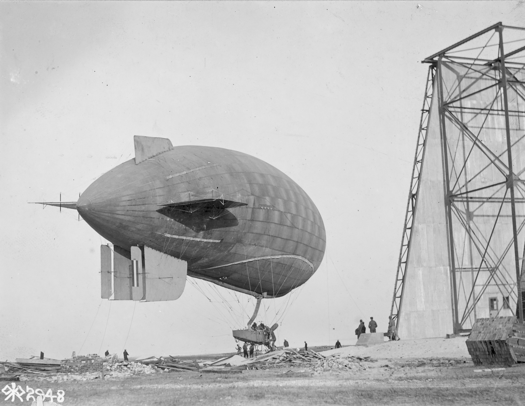
A B-Class preparing for takeoff. [US National Archives]The B-class was not without its accidents. Throughout their service life, many B-class blimps would suffer damage or be completely destroyed while on duty. B-4, B-5, B-6, B-7, B-9, B-12, B-14 and B-16 were all destroyed in accidents before the end of the First World War.
B-Class at Akron Ohio. [US National Archives]Despite its effectiveness, the B-class was found to be lacking as a patrol craft, and the Navy would order a successor design in September of 1918 to amend the shortcomings of the B-class. This was the C-Class (no relation to the aforementioned British Coastal Class which was also known as the C-Class coastal airship) and it took many aspects of the B-Class and improved upon them. The shape of the balloon itself was overall the same, but the C-Class had a much larger gondola that sported two engines instead of one, granting improved speed and maneuverability. The C-Class however wouldn’t be ready before the end of the war, but was instead operated postwar.
The B-Class Postwar
View of a B-class during operations patrolling the Atlantic. This photo was taken from a USN submarine. [US National Archives]The First World War would end on November 11th, 1918, with the B-Class having served well in its duties. Despite the C-Class approaching production, the B-Classes still in service would continue to operate, however a few were stricken off to reduce the fleet size. Three B-Class blimps would be rebuilt reusing the envelopes from previously damaged blimps. These would be B-17, B-18 and B-19. B-17 is known to have reused the envelope from B-1, which was damaged on June 17th, 1920. B-18 likely used the envelope from B-13. Details on B-19 are lacking. It is known that these three blimps were constructed sometime in 1920. The final B-class built would be the B-20. Details are also sparse on this craft but it is known to have had a completely unique gondola design and was much larger than the standard B-Class. In the bureau number list, B-20 is listed as being before the aforementioned rebuilt gondolas. Interestingly, these B-classes were all built after not only the introduction of the C-Class, but even after its successor, the D-Class. All postwar built B-classes were constructed by Goodyear. The remaining B-classes continued to serve into the early 1920s, with many of them being scrapped due to accidents or deterioration with age. By 1924, three B-classes remained, B-3, B-8 and B-15. B-8 was heavily deteriorated but B-3 and B-15 were still in operational condition. By this point however, the B-class was heavily outdated, and with its services no longer required, the last 3 were surveyed and scrapped in 1924. The B-class actually wound up being in service longer than its successor, as the few remaining C-Classes had been scrapped in 1922.
Conclusion
A B-Class above the Naval Air Station at Key West, Florida. [US National Archives]The B-Class was an important achievement to the United States Navy, proving the effectiveness of patrol airships and paving the way for a long line of succeeding designs. The B-Class would train aviators that would go on to protect allied countries in foreign built dirigibles, and would protect the American coasts from U-Boats. B-Class blimps would serve the Navy well past its expiration date, even surpassing its own successor. The Navy’s LTA airship fleet began with the humble B-Class, and would continue for almost five decades later.
One of the early B-Classes built by Goodrich. Notice the double ventral fins. [US National Archives]
Service List
B-1: The first in the B-Class series, B-1 would survive the war. On June 17th, 1920, B-1 would be damaged at Pensacola and would be stricken off. The gas bag was later reused on B-17.
B-2: B-2 would survive the war and would be stationed at Key West. On February 28th, 1919, B-2 would completely wreck.
B-3: B-3 would survive the war and continue to serve until it was surveyed in 1924. The ship was damaged several times but was fully repaired each time.
B-4: Stationed at Hampton NAS for testing. On August 8th, 1918 the craft was damaged and stricken. The blimp was salvaged for spare parts.
B-5: Stationed at Akron. While on maneuvers, it would be completely destroyed on November 21st, 1917.
B-6: Service details are lacking, stricken from the Navy on September 7th, 1918.
B-7: Stricken June 8th, 1918.
B-8: Survived the war and served until March 19th, 1924, where it was surveyed due to deterioration.
B-9: Stationed at Key West. On April 21st, 1919 would completely wreck due to engine failure.
B-10: Stationed at Cape May. During maneuvers on December 7th, 1918, it would be heavily damaged. The craft was sent back to Goodrich but the repairs were considered too expensive and B-10 was scrapped. The envelope was torn up and distributed to other air stations to serve as repair materials on other blimps.
B-11: Shipped to Pensacola, service ended on August 15th, 1919. Service unknown.
B-12: B-12 wrecked while on patrol on July 26th, 1918.
B-13: Damaged numerous times during service at Montauk Naval Air Station. Envelope appears to have been salvaged and later reused but on what aircraft is unknown, possibly B-18. It was recommended to be stricken off at two different stations in 1919, at Montauk and Rockaway.
B-14: Wrecked July 20th, 1918 at Montauk(?).
B-15: Served at Pensacola through the war and after. Was finally surveyed on April 22nd, 1924.
B-16: Official report is spotty but on June 17th, 1918, the craft was destroyed.
B-17: Rebuilt gondola, reused the envelope from B-1, service unknown.
B-18: Rebuilt gondola, envelope possibly from B-13. Service unknown.
B-19: Rebuilt gondola, service unknown.
B-20: Last B-class. Built in 1920. Completely new gondola design. Service unknown.
Variants
Goodyear/Goodrich B-Class (1 through 14) – B-classes built by Goodyear/Goodrich would use Curtiss OXX-2 engines. The first few of these had double fins but these were later changed to a single fin.
Connecticut B-Class (15 & 16) – The two B-Classes built by Connecticut would use Hall-Scott engines. These two appear to have the double fins as well. Unknown if any of these were later changed.
B-20 – The last B-class produced. It would have a unique gondola design.
Operators
United States of America – The 20 B-classes built would be operated by the United States Navy for patrol and training purposes until 1924.
B-Class (Goodyear) Specifications
Length
160 ft / 48.8 m
Diameter
31.5 ft / 9.6 m
Volume
(Varies between companies)
77,000 ft³ / 2180.4 m³
Engine
1x 100 hp ( 73kW ) Curtiss OXX-2 8-cylinder engine
USA (1915) Observation & Training Balloon – 10+ Built
The Kite Balloon operated by the Navy at Pensacola. This particular balloon is based off the first patent. [Naval History and Heritage Command]The Upson Kite Balloons, also known as Goodyear Kite Balloons or simply Upson Balloons, were a series of three observation balloon designs by Ralph Hazlett Upson to improve upon the design of the German Parseval-Sigsfeld Drachenballon. Two of the designs would be built by the Goodyear Corporation and sent to various balloon training schools and even operate off of ships, but the type was found to not offer much improvement over the Drachenballon, and the much more advanced Caquot balloon which would be introduced only a year after the Upson balloons were built, making the type null. A 3rd design would be patented but wouldn’t be built.
Ralph H. Upson and the Parseval-Sigsfeld Drachenballon
R.H Upson outside of the Goodyear Hangar in Akron, 1917 [US National Archives]Ralph H. Upson was a pioneer in balloon and airship development in America in the early 1900s. In 1913, using his own airship design, he would win the International Balloon Race. Upson was an employee of the aeronautics division of the Goodyear Rubber and Tire Corporation where he was a pilot and engineer on the various lighter-than-air projects the company had been working on. Upson would mainly work at the Goodyear plant in Akron, Ohio. In 1914, the company began building observation kite balloons for the US Army to use in their balloon divisions. The main type of kite balloon in use was the German designed Parseval-Sigsfeld Drachenballon. The Drachenballon was designed over a decade before in 1898 and was a replacement for the spherical observation balloons of the previous century, as the latter was found to be almost unusable when in windy conditions. The Parseval-Sigsfeld design was built in such a way it would face towards the wind thanks to a large, air-inflated steering bag at the rear of the balloon. Thus it was named Drachenballon, or “kite balloon”. America would build and operate several Drachenballons before their entrance into the First World War.
An example of a German-operated Parseval-Sigsfeld Drachenballon. [Waffen Arsenal 149]Upson would begin designing an improvement over the Drachenballon in 1915. Using the knowledge he learned from working on airships, he’d incorporate a number of features that would hopefully improve the overall stability of the German balloon. Two designs would be created at first in late 1915, with the patents on these designs being filed on June 20th, 1916.
Kite Balloon Design 1: Back to Basics
Kite Balloon Design 1 in the patent. The Navy-operated balloon in Pensacola is of this type. [Google Patents]An Upson balloon being inflated at Pensacola. [State Archives of Florida]The first of these designs was essentially a heavily modified Drachenballon. Its overall appearance and construction was the same. The balloon consisted of a large cylindrical gas bag. In the nose was a valve that regulates the pressure and gas and can be opened for release automatically or manually. On the underside was a neck to which the hydrogen gas was filled from. The Upson’s balloon’s neck was much longer than the neck on the Drachenballon. On the sides of the balloon were two stabilizing fins. On the Drachenballon, these fins are rectangular in shape. On Upson’s design, these would be triangular in shape and would sag down in flight. According to Upson, the rectangular fins of the Drachenballon only offered stabilization horizontally, while his fins would also prevent yaw and pitch movement. Internally at the rear was a large air bag to keep the balloon’s shape stable if the balloon isn’t fully inflated and keep the balloon at a 30-40 degree angle while in the air. The main difference between Design 1 and the Drachen involved the aft section of the balloon. On the standard Drachen is a large air-inflated steering bag that would keep the aircraft stable. On Upson’s design, the balloon would instead slightly taper at the rear. The steering bag would be removed altogether, instead replaced with a large keel-shaped bag. Upson’s thinking behind this change was that the steering bag wasn’t aerodynamic and instead opted for the more sleek keel bag over it, improving airflow. The keel bag and the ballonet were both connected via an intake at the tip of the keel. In addition, the tail of the balloon was connected to the keel, to which several tail cups were placed not only for stabilizing but to keep the keel straight. The tail cups were placed much closer to the balloon than on the Drachenballon. The rubber balloon girdle also differed from the Drachenballon slightly,as it wouldn’t be uniform all around the balloon, instead dipping slightly down near the front. The balloon would be made of rubberized and non rubberized fabric and filled with Hydrogen.
An Upson Kite Balloon in flight [US National Archives]One of the Upson balloons preparing for flight at the Goodyear Plant in Akron. The other is visible in background hangar. The USAAC roundel is barely visible on the underside. [US National Archives]BC-3 moored to the USS Huntington. [Wikipedia]The Upson balloon BC-3 operating off of the USS Huntington. [navsource.org]The Navy Design 1 balloon operating from the USS Oklahoma [NavalHistory.org]Several Design 1 balloons are known to be built. The first would be built at the Goodyear plant in Akron in late 1915. While testing was going on in November, it was observed by officials from the Navy who were looking to increase the USN’s LTA (Lighter Than Air) fleet. The Design 1 balloon was accepted into service for the Navy on December 22th and shipped to the Pensacola Naval Air Station in Florida. The balloon would finally arrive on April 5th, 1916, along with a handful of Goodyear employees who helped with training. Only two days after arriving, the balloon would be damaged from heavy winds and would break from its mooring. The balloon would be repaired shortly after. Once repaired, the balloon was stationed aboard the USS Nevada and USS Oklahoma for testing. The balloon was found to offer increased visibility, but there were a number of reasons why using it from a battleship was a bad idea. The balloon was a very easy target, explosive due to its hydrogen gas (which often leaked), and gave away the position of the battleship. Inflating the balloon was also slower than what was expected. In some cases the balloon itself affected the maneuverability of the ship. It was noted that many of these issues could be fixed in the future, but no changes to this balloon are known to have occurred. Despite not performing well aboard a ship, the Navy continued to use the Design 1 balloon at the Pensacola Air Station for testing and training. Two more balloons were ordered, with the designations of CB-2 and CB-3 for the Navy. Both of these balloons are known to have been tested on the USS Huntington for evaluation. Even further on, the balloon CB-4 was ordered. It is unknown what type of balloon this was, whether Design 1 or 2.
Photo of a Design 1 balloon at Fort Omaha, Nebraska [Museum of the United States Air Force]Aside from the Navy, the United States Army Air Service would also use two Design 1 balloons. One is known to be used for testing purposes. This balloon in particular has an extra set of stabilizing fins located a few feet in front of the regular stabilizing fins. Aside from testing, its service history is unknown. All that is known about it is comes from a US Army report evaluating it and a few photos to go along with said report. The report was very appraising of the type over the standard Drachenballon. The second known USAAS Design 1 balloon had an interesting history. From 1910 to 1919, the United States was in an armed conflict with Mexico on its border, known as the Mexican Border War. During this, many Army units would be stationed along the border. An Ohio National Guard Artillery unit was deployed along the border and stationed at El Paso, Texas in 1916. Accompanying the division was a Design 1 kite balloon gifted to the division by Goodyear. Along with the balloon, Ralph H. Upson himself would be assigned to assist in operations and training personnel for the balloon. The balloon would be used to observe Mexican forces moving near the border. Aside from its service in the War, the fate of this balloon is unknown. It was, however, the first observation balloon operated by the National Guard and is known to have been built shortly after the first Design 1 balloon.
Kite Balloon Design 2: All New
Design 2. This particular type would see several produced. [Google Patents]The second design was also included on the June 20th patent and would greatly differ from the standard Drachenballon. In fact the only two similarities between the two designs would be their overall layout, other than this, the two designs are greatly different. The overall shape wasn’t cylindrical, but instead more round. Carrying over from Design 1 are Upson’s unique side fins, keel bag, and extended neck. The evacuation valve in the nose was moved upward and is near the top of the nose instead of directly frontally. Instead of having a balloon girdle, the ropes connecting the mooring line and basket were instead connected to individual rubber connection points around the main body of the aircraft. The pattern of the connection points is the same shape as the girdle on Design 1, with it arching down towards the front. The aircraft would also be stabilized by an internal ballonet. Specifications for this balloon do exist. It was to have an internal volume of 25,000 ft³ (707.9 m³). The maximum service ceiling would be 6000ft (1828.8 m). On the underside of two of the balloons, a United States Army Air Corps roundel is printed.
Goodyear would build at least four of this balloon type for training and testing. Two of these would be sent to the Fort Omaha balloon school in late 1916. Here they would be used in the training of the balloon corps alongside Drachenballons and spherical balloons. Two more of this type were photographed at the Goodyear Akron plant during a maneuver with other lighter-than-air aircraft. There is a chance these two aircraft are the same as the ones in Omaha but their overall appearance differs slightly. On one of the balloons is a box-like structure located at the side of the balloon. These are not present in the patent or on the other balloons and their purpose is unknown. It is possible these were some form of additional stabilizers but it is not confirmed. This type appears to be exclusively used by the USAAS.
The same excercise as before at Akron with all balloons now airborne. What appears to be a B-Class Blimp is in the background as well. [US National Archives]On September 23rd, 1916, two pilots; Carl K. Wollam and Charlie Roth, were interested in one of the Goodyear Design 2 balloons then stationed at Dayton, Ohio. Both men, who were aircraft pilots, wanted to see how well the Upson balloon would do in untethered flight. It should be noted neither man had piloted a balloon before. The two would go up in the balloon, and then cut the cable. The balloon would go to an altitude between 5000 and 6000 ft (1524 and 1828.8 m) for a distance of over 120 miles (321.9 kilometers). The flight would last over 3 hours. The two wanted to head to Akron to land but their attempt failed and they were thrown off course for 70 miles (112.6 kilometers), finally landing in a farm near Circleville, Ohio. This would be the first free flight of a kite balloon in the US. Despite not being designed for this flight, the pilots said the balloon was hard to control, but overall performed well for the task.
Kite Balloon Design 3: Double Trouble
Side view of Design 3. This design was essentially two Design 2 kite balloon bodies sewn together. [Google Patents]Frontal view of Design 3. [Google Patents]The last of the Upson balloon designs was not included in the first patent document, instead being patented a few months later on November 9th, 1916. This 3rd balloon design differed greatly from most balloon designs of that era. Design 3 essentially was two Design 2 balloons sewn together side by side. Upson would call it a “Composite Balloon” in the patent. Each side of the balloon would have design features from Design 2. At the rear interior of the gas bag was an air-fed ballonet to keep the overall shape of the balloons intact when not fully inflated. The overall shape of the gas bag was changed, with Upson specifically mentioning that the bottom was flattened out to aid in aerodynamics. In each nose was an emergency gas escape valve to regulate the gas. On each side was one of Upson’s triangular stabilizing wings and at the rear was the keel bag. Instead of the tail cups that were common for kite balloons and used with the previous two designs, Upson would design a completely new tail stabilizing device. A large concave strip would connect to two ropes. Each rope would connect to an end of one of the gas bags. The strip would catch the wind like a parasail, stabilizing the balloon. Upson’s overall choice for the double body design was to greatly increase the stability and maximum height over contemporary balloon designs, with the idea that another body would assist in that regard considerably. The ropes connecting the basket were equally distributed to each of the balloon bags.
Despite Upson claiming it to be superior over his previous two designs, no composite balloon was ever built.
Too Late: The Caquot Arrives.
Two Upson Balloons are part of an exercise at the Akron Goodyear Plant, along with two Caquot Balloons. The photograph label incorrectly states all four balloons are Caquot R Types. [US National Archives]From reports, the improvements done by Upson over the Drachenballon design did positively impact its design, making it much more stable in strong winds. A Design 1 balloon is known to have remained stable in 45mph winds. Despite the positive reception, there are still mentions that the Upson balloons design wasn’t perfect and it suffered still in terms of total stabilization compared to newer the newe balloons on the horizon, but overall it performed better than the Drachenballon in this regard. Upson’s balloon designs would have only just started their testing when the French officer, Albert Caquot, would create his superior balloon design in the later months of 1916. The design was created to completely fix the flaws of the Drachenballon. To fix the stability issues, two more air-inflated bags were placed at the rear of the balloon, totalling 3 stabilizers spaced 120 degrees apart from each other. The type was found to be completely superior over the Drachenballon and it quickly began replacing allied, and eventually German Drachenballons. Goodyear would later license build Caquot type balloons in 1918, for use by the American Balloon Corps. By their entrance in World War One, the US would only use Caquot types in combat operations in Europe. No further Upson balloons were built after 1917. Despite this, the two Design 2 balloons stationed at the Fort Omaha balloon school would continue to be used for training purposes until the closure of the school in 1919. It is unknown what fate befell the Navy operated kite balloons.
The Design 1 Balloon in operation at El Paso, Texas during the Mexican Border War. [texashistory.unt.edu]An Upson Balloon at the Fort Omaha Balloon School. [US National Archives]Due to a lack of information regarding these balloons, it is entirely possible, and extremely more than likely that more than the known amount of Upson balloons were built, but records and photos concerning the production of Design 1 and 2 types are severely lacking.
Upson would continue his work in the field of lighter-than-air aviation, working for Goodyear into the 1920s until he would leave the company to pursue his own vision of lighter-than-air aircraft. He would create the Aircraft Development Corporation, where he would design and build the metal-skinned airship ZMC-2 for the Navy. Upson would continue in the aviation industry all the way through the Second World War and into the 1950s.
A B-Class Blimp flies over the Goodyear hangar in Akron. One of the Upsons is being either taken in or out of storage. The second is visible in the hangar. [US National Archives]
Variants
*Note, the “Design” names are not the official designation, but named so here for simplicity.
Design 1– Heavily modified Drachenballon with improvements made by Upson. These include larger side stabilizers, the removal of the steering bag and the new keel bag for wind stabilizing. Five are confirmed to be built, with a possible 6th.
Design 2 – Completely original design that took the improvements from Design 1 and put them on a new design. Design 2 had a much more rounder body over Design 1. Four are known to have been built.
Design 3 – Composite balloon. Consisted of essentially two Design 2s sewn together. Reused all of the aforementioned modified side fins and keel bags. Would have a unique tail stabilizing parachute.
Operators
United States of America – The Upson types built were used by the balloon corps of the United States Army Air Corps and Navy.
Upson Kite Balloon Design 1 Specifications
Length
82 ft / 25 m
Diameter
22 ft / 6.7 m
Volumes
25,000 ft³ (707.9 m³)
Gas Type
Hydrogen
Material
Rubber-infused and non-infused cotton fabric
Maximum Service Ceiling
6000 ft / 1828.8 m
Crew
2 Observers
Equipment
Telephone
Upson Kite Balloon Design 2 Specifications
Volumes
25,000 ft³ (707.9 m³)
Gas Type
Hydrogen
Material
Rubber-infused and non-infused cotton fabric
Maximum Service Ceiling
6000 ft / 1828.8 m
Crew
2 Observers
Equipment
Telephone
Gallery
Illustration of Upson Balloon Design 1 by Ed Jackson
Austro-Hungarian Drachenballon in 1917 [US National Archives]The Parseval-Sigsfeld Drachenballon was a German observation balloon designed to replace the older spherical-type balloons used for nearly a century. The balloon would be designed in such a way that it would face into the wind, and be much more stable over its predecessor, using design attributes similar to kites. The Drachenballon would be used in several wars over its lifetime, including widespread use during the First World War. Here, it saw service on almost all fronts, and would even be copied by the Allies. The type would eventually be replaced by the much more stable Caquot/Type Ae 800 observation balloons in 1916, but despite this would continue to see service until the 1920s.
The Spherical Balloon: An Outdated Design
Two German spherical balloons in 1896. These balloons could only be used in good wind conditions, any rough weather would jostle the balloon around. [Waffen Arsenal 149]The idea of using balloons as a means of observation in war dates back nearly to their initial conception in the late 1700s. An aerial observer allowed an army excellent view of the battlefield below, offering a strategic advantage over your enemies. The first time a balloon would be used in war for this purpose would be at the Battle of Fleurus in 1794 during the French Revolution. Balloons would continue being used in several smaller roles in later wars, such as the American Civil War and the Boer Wars, but would never see widespread use in large numbers. Beginning in the late 1800s, balloon corps began forming in sufficient numbers, all using the same type of spherical tethered balloon design that had been used for nearly a century without design changes. While it allowed observers to be elevated to altitudes sufficient to observe the battle, it was not the most stable of designs. Spherical balloons, when encountering even a light wind, would be thrown about. This severely limited when the balloon could operate, as even slightly windy days could prevent the aircraft from operating efficiently. The swaying from the wind also made it difficult for the operators to observe the battle and would oftentimes make them very air sick. Despite this, the design was the only type of observation balloon used for nearly a century.
Two French Type H balloons with a Type E spherical balloon. [Imperial War Museum]
The Parseval-Sigsfeld Drachenballon
Diagram of a Drachenballon from Balloons and Airships, 1783-1973
The German Empire was no exception in this field and had their own balloon corps formed after seeing the success of observation balloons in the American Civil War. Like the rest of the world, they too would use the simple spherical balloon type until the 1890s. In the early 1890s, two German officials; Major August Von Parseval and Captain H Bartsch von Sigsfeld began working together to create a new type of balloon to address the problems associated with spherical balloons. The two had extensive experience with designing and using balloons for military applications. Attempts to remedy the old spherical balloon had been attempted in the past, but none of these would ever be successful. Parseval and Sigsfeld would use the knowledge gained from these past attempts to develop their own replacement. Testing of the new type began in 1893. Many different shapes, sizes and layouts were tested over several years, until in 1898, the final design for their observation balloon was completed. The new design was named the Drachenballon, literally ‘kite balloon,’ as it would glide with the wind, with the German spelling ‘ballon.’ The balloon was designed in such a way that it would face into the wind, instead of being blown around by it. Balloons designed in this way would from then on be called kite balloons. The Drachenballon would mostly serve as a captive balloon, or one that was connected to the ground via a cable. With the design proving to be a major improvement over the old spherical balloons, mass production soon commenced. Production of the type initially began at the August Ridinger plant in Augsburg, Germany. Here the balloons would be produced as well as the vehicles necessary to transport and support the balloons. The type quickly became the mainstay for the German Military for aerial observation duties, both by the German Army and the German Navy. For the Navy, Drachenballons would be carried aboard large warships and sent up for rangefinding and battle observation. Despite being superior to the spherical balloons, the two types were still used together in balloon companies until the early 1900s when the Drachenballon completely replaced the older spherical type.
Design
Two German Drachenballons in different colors. The closest is painted green while the background is tan. The tan balloon’s ballonet isn’t inflated yet. [Waffen Arsenal 149]The Drachenballon was a captive observation balloon developed for the German Empire. The main body consisted of a large cylinder shape made out of rubberized fabric that was filled with hydrogen gas. Gas pressure and release was regulated by a valve in the nose of the balloon. It could do so automatically, or manually via rope. At the rear of the body was an internal air bag, or ballonet, that was filled with air via the wind to keep the balloon’s shape if the hydrogen gas bag was not fully filled yet. Underneath the ballonet was an air inlet that was fed directly by the wind. On the underside of the front of the balloon was its neck, where the hydrogen gas would be pumped into the gas bag while it was on the ground. Two valves placed on each side of the gas bag/ballonet could be opened to quickly release the gas/air and descend. On each side of the balloon’s body was a small stabilizing fin. Early examples of these were triangular in shape, but they became rectangular near the outbreak of World War I. At the back of the body was a steering bag that was sewn on. The steering bag was made of regular fabric and was designed to keep the balloon stable and facing into the wind. The steering bag was inflated by wind via a large intake at the bottom of the bag facing forward, and a smaller intake located on the bag itself. At the top of the steering bag was a safety valve that permitted excess air to escape. The steering bag was held together via rigging to the main body. Connected to the steering bag was the tail of the balloon, which was a long cable with up to 6 removable tail cups, resembling small parachutes which trailed behind the main balloon, that helped with stabilization. The balloon would face towards the wind at an angle of 30-40 degrees. Slightly below the equator of the balloon was the balloon girdle. This was made of rubber and served as the attachment point for all of the balloon’s rigging. Various ropes were used for the rigging, which kept the different parts of the balloon together. Three colors of rope were used to differentiate their specific sections; white, red and blue. Blue rope was rigging for the steering bag, white rope was for cable rigging and red ropes connected to the observer’s basket. It is unknown if rope colors were used throughout its service or if the copies used by the Allies also used colored ropes. The cable that connected the balloon to the ground and the ropes that connected the basket were different ropes and were not connected together. On the ground, the steel mooring line was connected to a pulley that prevented the balloon from moving and could lower or raise the balloon at will.
A balloon operator fires a signal gun in the basket of a German Drachenballon. [US National Archives]The basket of the Drachenballon was made of willow and bamboo and was secured to the balloon by four ropes. These ropes were adjustable by the crew to prevent the basket from swinging around. Accommodations for the observer were located in the basket. A telephone could be placed in the basket and would have its cable connected to the ground via an internal wire that went through the mooring cable. Two pockets were located inside the basket to store equipment, as well as ten metal cases to protect valuable reports. Once a report was finished, it was put into a case and dropped from the balloon to the ground. Flags were put on the cases to help the ground crew find them more easily. Standard operating height for captive observation balloons were 500m, but if the weather was rough, the balloon would be raised to 300m instead. The larger Drachenballon variants created during the First World War would be able to achieve a maximum height of 2,000 meters. Inflation of the balloon would take 15 minutes, with ascension taking 10 minutes and descent taking 5 minutes. Equipment used by the observer included maps, notebooks, two signal flags (one red, one white), a barometer, a knife, two looking glasses of varying magnification, and a signal disk to show what commands could be done with the flags. Later on during the First World War, parachutes would also become standard onboard equipment. Additional equipment that could be carried included signal flares, a flare gun, or a camera. On Drachenballons used by the Navy or aboard ships, life preservers were standard issue. A single observer would remain in the basket during operations but up to 48 men made up the ground crew that would handle moving, inflating, deflating, and transporting the balloon and its associated equipment.
A German Drachenballon being fired upon by flak. [Imperial War Museum]The Drachenballon would be used for observation of enemy troop positions and movements, and would report on the current situation of the battle. Gun sighting and fire correction were also reported during battle to adjust the accuracy of artillery used near the balloon. Aboard ships, the Drachenballon was used for rangefinding purposes. During the First World War, submarine spotting was an additional duty naval Drachenballons were used for.
Drachenballons of the German Army were standard tan or dark green in color. On the sides and on the underside was an Iron Cross emblem to identify its operator. Allied countries would not have these emblems on their balloons and their exact colors are unknown. Russian Drachenballons were known to be white.
The 1900s: The Drachenballon Goes To War
A German Drachenballon prepares to go up, 1915. [Rolf Kranz]The Drachenballon would see its first operational use in wartime in 1904 during the Russo-Japanese war. Imperial Russia had acquired several Drachenballons from Germany around the outbreak of the war, and would use them in the conflict. The first battle Drachenballons would be used in would be the Battle of Port Arthur. Aside from land usage, the balloons were also used by the Russian Navy, one such Drachenballon was used aboard the Armored Cruiser Rossia for observational duties and for directing fire of the main guns. The balloons would be used through the war until the final battle at Mukden.
Drachenballon on the Eastern Front in 1916. [Waffen Arsenal 149]In 1909, Sweden would purchase five Drachenballons from Germany to use for their military. The type would be named the Drakballong m/09, with three going to the Royal Swedish Army and two going to the Royal Swedish Navy. Two m/09s would be sent to the Swedish Balloon Corp stationed in Frosunda for training. The Swedish Royal Navy would purchase a barge from Britain and convert it into a balloon carrier. The ship would be designed to house and operate the two m/09s the navy operated and was named Ballongfartyget No 1. Sweden would continue to use the m/09 until 1926.
Also in 1909, Spain would use a Drachenballon they built from purchased plans during the Campaign of Millela.
In 1912, the Italians would use the Drachenballon during the Italian-Turkish War for observing Turkish positions. These were purchased from Germany. The Italian-Turkish War was a major stepping stone in regards to aviation, being the first use of combat aircraft in war, and would serve as a prelude to what was to come in only a few years. Italian Drachenballons would also be used during their involvement in the First Balkan War. Aside from Italy, Bulgaria would also use Drachenballons during this war.
Romanian operated Drachenballon. [Imperial War Museum]In 1914, Europe would be plunged into the First World War, with most armies across Europe participating in combat. Germany would enter the war only days after its start, first declaring war on Russia on August 1st, then against France on the 3rd. Despite declaring war in August, the first balloon companies wouldn’t see action until October. On the fronts, the Drachenballons were used as observation balloons and rangefinding for artillery. Each balloon company would be its own division in the army it was attached to. By the end of 1915, over 80 Drachenballons were in service with the German Army. The majority of the balloons used at this point were still 600 m³ volume, but newer 800 m³ and 1000 m³ volume models had begun production. The increase in size was to improve overall stability, and to allow greater altitude to be achieved. The largest type would be 1200 m³ volume. Austria-Hungary would receive several Drachenballons from Germany for their own armies to use. These balloons would be used on the Italian Front and several would be lost to enemy fighters. The Austria-Hungarian Navy would also use Drachenballons aboard ships. German Drachenballons saw mass deployment during the Battle of the Verdun in February of 1916, directing the large number of artillery regiment on the German side. Due to their success at Verdun, more balloon divisions were formed.
An interesting German Drachenballon. This particular example appears to be two tone colored [Imperial War Musuem]The shape of the Drachenballon became iconic in World War One, earning itself many nicknames. The most common was “sausage” in reference to its overall shape, and maybe its German origin. Many other nicknames were spawned from its overall shape, most of them phallic references. Overall, Allied countries would simply refer to them as kite balloons or shorten the name to just “Drachen”
Underside of an Drachenballon, the two side fins are clearly visible. [US National Archives]During the Battle of Flers, the first battle to use tanks operationally, the Mark I tank D17 “Dinnaken” fired once upon a German Drachenballon as it charged Flers. The shot is noted as either closely missing or hitting the kite balloon, but not destroying it. In response, the balloon was likely lowered by the observers and ground crew to avoid being fired upon again. The diary of the tank reported that Gunner Reiffer claimed that the balloon was brought down manually and that Gunner Boult was the one to claim the hit. This was later claimed by Reiffer as himself shooting down the balloon and destroying it in a 1963 book. This incident could be cited as the first “kill” of a tank in combat, but the balloon itself was not destroyed, making this claim untrue.
At the outset of the war, most Allied countries would still be using spherical balloons. France in particular had large numbers of the type in service, and Russia would still have their Drachenballons they had purchased from Germany in the early 1900s. Italy would also continue to use their Drachenballons from the previous war once they entered the fray. Belgium would start the war off with a single 800 m³ Drachenballon they had purchased from Germany years before. In late 1914, France would copy the Belgian Drachenballoon’s design and would begin mass producing the type under the name Ballon Captif Type H. The French would also begin selling the Type H to other allied nations. In February of 1915, British officials would do a test flight of a French Type H and would soon after make a purchase of an unknown amount of these balloons for their empire. After this, they would produce their own copied versions of this craft. Britain would make heavy use of Drachenballons on several of their fronts in the Royal Army, and with the Royal Navy. The Royal Navy would have several specially designed ships created solely for the purpose of carrying kite balloons during fleet operations. The early ships of this type would use Drachenballons. Several examples of these ships include the HMS Manica, HMS Hector and HMS City of Oxford, all of which were designed to carry and operate the Drachenballon. These balloons were used to not only observe and direct guns, but as the threat of submarines became more prevalent, the balloon operators began looking for submarines as well. Minesweeping also became a common use for RNAS (Royal Naval Air Service) Drachenballons, where the balloon would be raised to detect incoming mines from the air. Several other nations would end up using the Drachenballon, but the details of their acquisition and use are lacking. Romania and Switzerland are two such examples.
Balloon Observer jumps from a Drachenballon via parachute. The tail and its cups are clearly visible. [US National Archives]As the war went on, the use of combat airplanes increased. In particular, fighters began being produced in larger numbers. This posed a problem to the Drachenballon, as these large and stationary balloons became easy targets. Taking down a balloon was considered the same as shooting down an enemy plane, so the Drachenballon became a prime target for aviators. Many of the special weapons employed against airships were used against observation balloons, such as incendiary rounds designed to ignite the flammable hydrogen gas, or the fabric skin of the balloon. It therefore became imperative that the balloons be protected and defensive measures be developed. German Drachenballons began to be defended by a number of anti-aircraft guns and patrolling fighters, to protect the observers as they did their duty. Another improvement made was enhancing the performance of the electric winches which lowered the balloons, allowing the balloon to be brought closer to its defensive guns more quickly. These countermeasures made ‘balloon busting’ a much more hazardous job than before, as pilots had to get in close to the balloon to avoid encountering enemy defenses, as defenders would likely stop shooting at close range to avoid friendly fire on their balloons. Despite these improvements to defenses, balloon busting was still a job many pilots had to undertake, and for some pilots this was their only duty. A handful of pilots would be given the title of ace on destroying observation balloons alone. Interestingly, Drachenballon observers were the first on all sides to use parachutes in war, starting with Germany in 1915.
A US-operated Drachenballon at Fort Omaha, Nebraska in 1919. [US National Archives]America at some point would acquire or build their own versions of Drachenballons, however they also had their own kite balloon design. Ralph H. Upson, a balloon pioneer and engineer at Goodyear, designed his own improved kite balloon based on the Drachenballon. It would use his own stabilizing fin design, as well as remove the steering bag altogether, instead replacing it with an aerodynamic keel shaped bag that he thought would better flow with the wind. Two versions of this balloon exist, with the first essentially being a slightly modified Drachenballon. Despite this original design in use, America still operated a number of the standard Drachenballon copies. Two were stationed at the Fort Omaha Balloon school for training purposes. The first was nicknamed “Old Dutch” and its design differs from the standard appearance with it having an apparently different method of construction, and the side wings being much thicker. The second one stationed at Fort Omaha resembles the standard design of the Drachenballon. No evidence has been found that America’s Drachenballons were used in the First World War. By the time of their entry in the war, more advanced types had already been fielded, and the remaining Drachenballons would be used for training of the various balloon corps. Exactly how many Drachenballons were either built or used by the USA is unknown, as details are lacking.
The End of an Era: The Caquot and Type Ae 800
Type AE 800 in action. This was a copy of the French Caquot Type M balloon and would replace the Drachenballon in late 1916. [US National Archives]Despite its success replacing the spherical balloon, the Drachenballon didn’t fix all of the issues of its predecessor. Although it was designed to face the wind, it was found that at higher altitudes, winds would still move the balloon around to an extent that would limit the maximum effective altitude. No attempts from the Germans would be made to address this problem, instead it would be the French who would come up with an improvement to the design. In 1916, a French officer by the name of Albert Caquot began working on an intended replacement. Using the Drachenballon as a base, Caquot would come up with a new, much more stable design, the Ballon Type L. The Type L resembled the Drachenballon but had a much bigger steering bag that wrapped all the way around the rear of the aircraft in a single big fin. The type was further improved on with the Caquot Ballon Type M. The Type M balloon would have a much rounder shape than the Drachenballon. Instead of a single large fin at the bottom and two smaller stabilizer fins on each side, Caquot’s balloon would instead have 3 large, air-inflated fins placed 120 degrees apart from each other at the rear of the balloon. Caquot’s new balloon design was found to be completely superior to the Drachenballon in terms of stability. The placement of the fins helped keep the balloon steady in high winds, allowing the type to be much more stable and able to fly much higher. In due time, Caquot balloons entered mass production and were sent to the frontlines, replacing both the spherical balloons still in service and the Drachenballons. Soon, Britain and other Allied countries like Romania, began operating Caquot balloons as well. America would start their entrance to the war using Goodyear-built Caquots for their observation role.
In the later months of 1916, the German Army would capture a British Type M balloon. Coming loose due to a broken mooring cable, the balloon managed to drift behind German lines where it was captured. The German Army was quick to study the new design, and like the Allies, found it a much more stable design over the Drachen. The Germans would copy the Caquot design under the name Type Ae 800 (English Type, 800m3 volume) and would begin mass producing the type to replace their older Drachenballons. The Type Ae 800 became the standard observation balloon from this point forward for the German Army, and the Drachenballon would be slowly retired from service. During the Second World War, Germany would use a derivative design of the Type Ae 800 in the early stages of the war, as well as on the Eastern Front against the USSR. No further work on the Drachenballon was done by Germany after this point.
The Aftermath: Postwar Use-1920s
Basket of an Austro-Hungarian Drachenballon. [US National Archives]A total of 1,870 German balloons of both types were delivered to the front by the end of the war. With the signing of the armistice in 1918, all German observation balloons were ordered to be destroyed by the Allies under the Treaty of Versailles.With the primary user of the aircraft no longer able to operate it, and it already being replaced by a new type, one would think the story of the Drachenballon would end with the First World War. However, it would continue to be used in several countries for nearly a decade.
America would continue to operate their Drachenballons until at least 1919. By this point they had already been widely replaced years prior by the Caquot types. Because of this they were only used for training. Interestingly, at the Fort Omaha Balloon School, every type of balloon then in service was used, Drachenballons, Caquot, Goodyear/Upson, the Italian Avorio-Prassone, and even spherical balloons were still being operated until its closure in 1919.
In 1919, Poland would acquire a Drachenballon from a former German facility in Winiary, Poland. This Drachenballon would be used for training purposes for only a few months before being given to a museum in 1920.
Two USSR operated balloons in Red Square during a celebration, 1920. The foreground balloon appears to be a Caquot-type with its upper fins deflated while the background is a Drachenballon. [Waffen Arsenal 161]After the fall of Imperial Russia and the rise of the USSR in 1922, the Drachenballons operated by the former Empire would end up in the hands of the Soviets. These Drachenballons were used until at least 1925, and would be seen in parades and other exercises. The USSR would use the Drachenballon for a very interesting purpose. On several of their armored trains, a Drachenballon would be deployed from the train and would direct its artillery from above. These were eventually phased out of service.
Conclusion
British Army operated Drachenballon. [Imperial War Museum]Parseval and Sigfeld’s Drachenballon was an important evolutionary step in the design of the observation balloon, but it wasn’t the last. Although slightly mending the issue it was designed to solve, it would never completely overcome its stability problems, and was eventually replaced by a more advanced successor. Despite this, it served a crucial role in militaries across the world for the purpose of observation and artillery rangefinding for several decades, on land and sea.
After creating the balloon back in 1898, the two creators August Von Parseval and H Bartsch von Sigsfeld would continue to work with each other designing lighter-than-air aircraft. The two began working on an airship together until von Sigsfeld’s death in 1902 due to a ballooning accident involving a Drachenballon. Parseval would continue creating and building airships, some would rival even the larger Zeppelin airships in size, but they did not capture the same level of success.
A Swiss-operated Drachenballon before liftoff around the time of the First World War [Swiss Federal Archives]Italian Drachenballon being prepared for flight. [Imperial War Museum]British Royal Navy Drachenballon. These would serve on designated balloon ships for observation duties. [Imperial War Museum]A RNAS Drachenballon aboard the battleship HMS Benbow, 1916. [Wiki]British Army operated Drachenballon. [Imperial War Museum]To protect the balloon from weather, small sheds would be constructed in the field for cover. [Waffen Arsenal 149]
Variants
Parseval-Sigsfeld Drachenballon – The standard Parseval-Sigsfeld Drachenballon came in several volumes/sizes, but all retained the same shape and overall design.
Copied Drachenballon – The Drachenballon was copied by several countries without license. The designs of these copies may be consistent with the German design but some of these appear with details differing from the German version. The American “Old Dutch” Balloon appears to be one such example.
Ballon Captif Type H – French-built Drachenballons were given this designation.
Drakballong m/09 – Name given to five Drachenballons bought by Sweden.
Operators
German Empire – The Drachenballon was created by and widely used by the German Empire as a replacement for the spherical type. These would be produced through the 1890s until 1916 when the type would be replaced by the Type Ae 800 balloon.
Austro-Hungarian Empire – Austria-Hungary would use the Drachenballon as their main observation balloon during the First World War, being given to them by Germany.
British Empire – The United Kingdom would copy the Drachenballon for their own use. The type would be used by the British Royal Army and the British Royal Navy during the First World War. Several of the Empire’s Dominions would use the balloon as well, such as Canada.
France – France would begin copying the design in 1914 as the Ballon Captif Type H and would be used until 1916 in the First World War. These were tested to find out what could be improved on the design, which led to the creation of the Caquot balloons.
United States of America – The USA would operate Drachenballons until at least 1919. Several would be used during the Mexican Border War. The Drachenballon would serve as the basis of the Upson kite balloon.
Belgium – Belgium would operate a number of Drachenballons for observation use against the Germans in the First World War. They would purchase one years prior from Germany.
Romania – Romania would operate a number of Drachenballons during the Romanian campaign of the First World War.
Italy – Italy would use the Drachenballon during the Italian-Turkish War, First Balkan War and First World War.
Russian Empire – Imperial Russia would operate the Drachenballon by the White Army and the Imperial Navy. These would see combat operations during the Russo-Japanese War and the First World War.
Soviet Union – After the October Revolution, the USSR would use the Drachenballons used by the former Russian Empire for their own balloon corps. These would be used until at least 1925 when they were replaced by more advanced models.
Sweden –Sweden would purchase five Drachenballons from Germany in the early 1900s. These were given the designation of Drakballong m/09. Three would go to the Swedish Royal Army and two would go to the Swedish Royal Navy.
Poland – Poland would capture a single Drachenballon in 1919 and would use it for training purposes until 1920.
Spain –Spain would license build a single Drachenballon. It was used during the Campaign of Millelan.
Bulgaria – Bulgaria would operate the Drachenballon during the First Balkan War.
Switzerland – Switzerland operated an unknown amount of Drachenballons around the time of the First World War
Due to it being copied, several other countries could have ended up building their own versions or received some from the Allies or Germans.
A German Drachenballon, note the rope colorsAnother example of German Drachenballon with a lighter colored balloon material
Credits
Written by Medicman11
Edited by Stan L. & Henry H.
Illustrations by Ed Jackson
Sources
Angelucci, Enzo, and Paolo Matricardi. The Rand McNally encyclopedia of military aircraft, 1914-1980. New York Distributed by Crown Publishers: Military Press, 1983. Print.
Ege, Lennart A., et al. Balloons and airships, 1783-1973. London: Blandford Press, 1973. Print.
WAFFEN ARSENAL # 149: Deutsche Fessel- und Sperrballone 1900-1945+
WAFFEN ARSENAL # 161: Sperrballone über London-Moskau-Berlin 1917-1945
WIDMER, EMIL J. MILITARY OBSERVATION BALLOONS (CAPTIVE AND FREE) : a complete treatise on their manufacture, … equipment, inspection, and handling, with special. Place of publication not identified: FORGOTTEN Books, 2016. Print.