United States of America (1951)
Nightfighter & Electronic Warfare Aircraft: 265 built

Designed after the Second World War, the Douglas Skyknight was meant to be the defender of the American carrier group after dark. The ambitious design sought to use all of the lessons learned from night fighter design and tactics in the Second World War, and produced the first specialized all-weather jet fighter. While it would prove too cumbersome for use on the smaller WWII era fleet carriers, the Skyknight would prove to be an exceptional nightfighter when disembarked during its combat debut in the Korean war. Yet beyond the conflict, and entering rapid obsolescence as a fighter in the 1950s, the Skyknight would prove itself to be an able electronic warfare aircraft and a pioneering aircraft in its field.
American Night Fighter Experiences in WWII
The more advanced, radar equipped night fighter of the Second World War was an ad-hoc creation which combined state of the art airborne detection systems with often pre-existing fighter designs. The resultant creation was an interceptor capable of bringing down enemy aircraft at night, or in very poor weather. While they carried their own radars, the limits of their range required they be directed by ground controllers into the path of their target. Alternatively, they could be tasked with offensive patrols to harass the enemy over their own airfields or carry out ground attack missions. In either case, sorties were demanding, with the crews of these aircraft having to endure patrols of several hours, flying almost entirely by instruments, and occasionally in extreme weather conditions. Even without the dangers of aerial combat in the dark, flying these aircraft was often exhausting and dangerous work. Vertigo was as deadly an opponent as any enemy they might encounter. Unsurprisingly, the best qualities that these aircraft could possess were straightforward flying characteristics, like good handling and stability. A good night fighter needed to be uncomplicated, and forgiving in how it flew.

The American nightfighters of the Second World War can largely be broken down into two groups. These were the heavier, twin engine, land based types in use with the Army Air Force, and the lighter carrier-embarked forces of the Navy. The Air Force’s principle nightfighter was the Northrop P-61 Black Widow, a purpose built, if somewhat over-engineered design that saw use across Western Europe and the Pacific. The design was cutting edge, featuring a state of the art airborne intercept radar system, and an impressive, if totally unnecessary, remote controlled gun turret. It flew exceptionally well, was nimble beyond what its size would suggest, and was fast enough to catch all but high flying, fast recon aircraft. Yet the design had two serious limitations. Foremost was its disappointing endurance, as in spite of its size, its limited fuel capacity and massive Pratt and Whitney R-2800 engines meant it had a range comparable to many single engine fighters. This was partially resolved by the installation of wing pylons which could fit either fuel tanks or bombs, though having to choose between ordinance or range imposed significant mission limitations. Less serious was its poor crew layout. As designed, the pilot and radar operator sat at opposite ends of the fuselage, hampering communication and, in the event of an accident, the loss of the intercom completely isolated the radar operator from the other two crewmembers. This limitation was overcome by the crews of the 425th Night Fighter Squadron, who moved the radar operator’s equipment to the gunner’s position. However, this modification was almost entirely limited to the European theater.
While the P-61 proved a capable night fighter, and an excellent all weather ground attack aircraft, there was much to be learned from the Mosquito Night Fighter Mk. 30’s that were made available to American crews near the end of the war. The Mosquito featured a side-by-side pilot and radar operator arrangement, and a large internal fuel capacity that gave it excellent range without having to install external fuel tanks. While it was less maneuverable, it was arguably the best night fighter of the war, capable of pursuing targets over long distances and attacking enemy rear line airfields at night, without having to sacrifice ordinance for range.
In all, the experiences of the P-61 crews were mixed. In Europe, they provided good night cover for the Army Corps they were assigned to, and during the siege of Bastogne, they were among the only fighters providing protection and support to the beleaguered Airborne forces in the city, when poor weather kept all but a handful of aircraft grounded. In the Pacific, they were less successful, particularly towards the end of the war. During the battle for the Philippines, they often struggled to deal with the swarms of Japanese fighter bombers that flew dawn and dusk attack missions. The P-61’s were never designed or intended to defend against such forces, and found them a challenge to bring down. Where in Europe they gained the personal thanks of the commanding officer of the 101st Airborne Division within Bastogne, they were the target of General MacArthur’s personal frustrations as his beachheads were continually harassed by Japanese forces.

In contrast to purpose built P-61, the night fighters of the US Navy were fairly simple conversions of existing fighter planes converted to serve as a defense for carriers at night. Variants of the F5F Hellcat and F4U Corsair were fitted with small, wing mounted radar sets to allow them to track and engage targets at night or in poor weather at the direction of ground controllers. They were far simpler aircraft, and generally were tied down more heavily to their ground controllers as a result of their shorter range, and simpler radar systems. Within the fleet, the duty of these night fighters was to contend with enemy aircraft that attempted to attack naval vessels under the cover of darkness. When assigned to land based Marine corps aviation, they were typically charged with the protection of amphibious operations and providing air cover for important installations. In both cases, these light night fighters proved very successful, and in the case of the Philippines, F6F Hellcat night fighters ended up replacing P-61’s as the defenders of the beach head. However, the limitations of the single engine fighters left the navy wanting something more. The Hellcat and Corsair night fighters were fast, but they had a fairly short range, and lacked a dedicated radar operator. The benefit of the heavier night fighter was its ability to more easily re-acquire targets which may have evaded the first attack and longer endurance, which allowed it to pursue and catch fleeing targets over an extended chase.
The new F7F-N was hoped to be the ultimate carrier based nightfighter of the Second World War, carrying both a second crewman to operate radar and navigation systems, and having a significantly better range. However, it was not to see use during the war, it was too large, and it was soon to be obsolete. The piston engine was being superseded by the jet turbine, and the carrier air wing of the future would soon need an aircraft to contend with threats far faster than any of their existing fighters.
Douglas’ Dark Knight
In August of 1945, at the very end of the Second World War, the Navy’s aviation bureau set its requirements for a new carrier based, jet night fighter. It called for a top speed of 500 mph (805 km/h), a service ceiling of up to an altitude of 40,000 ft (12,192 m), and a 125 mile (201 km) radar intercept range. Beyond its performance requirements, it was to also carry a pressurized cabin with temperature controls, and a robust set of de-icing equipment. Four companies presented bids, these being Douglas, Curtiss, Grumman, and Fleetwing, with preliminary design work beginning in October. By April of the following year, the contest was over, with only Douglas’ proposal receiving a letter of intent, the resources to construct three prototypes, and ground testing materials. Its daylight counterpart was to be the Grumman F9F Panther, with the two fighters being poised to propel the US carrier forces into the jet age.

The design dubbed ‘Skyknight’ incorporated many of the lessons learned from the Second World War. The aircraft’s chief designer was the prolific Ed Heinemann, who designed some 20 aircraft through a very productive career. Some of his most notable creations were the venerable SBD Dauntless, AD Skyraider, and A-4 Skyhawk. His Skyknight featured a cutting edge search radar which was operated by a crewmember seated beside the pilot, allowing for easier communication. The radar was also to feature a fire control system which gave the pilot an accurate lead on his target, allowing him to engage maneuvering targets and those that were not visible to him. They attempted to fully resolve the drawbacks of the Black Widow by installing large internal fuel stores, but the high fuel consumption of the turbojet engines meant the aircraft had comparable range to most other jet fighters of the era. Beyond its combat ability, it was to be a very straightforward aircraft to fly, with stability at both extremes of its speed limits. Its only eccentricity was that it had an ejection chute as a means of crewmen to escape the aircraft in an emergency. Altogether, it was a conventional, honest aircraft that flew well.
The first XF3D-1 prototype was flown by test pilot Russ Thaw on March 23, 1948, with the second flight following in June, and the final in October. Apart from basic safety and performance tests, the aircraft was flown in mock intercepts against single seat jet fighters. Even with their World War II era SCR 720 radar, they easily managed 85 mile (136 km) intercepts with GCI support. The Air Force also conducted tests on the aircraft, and inquired about installing the fighters with afterburning engines, but declined and instead developed the all-weather F-89 Scorpion.

After satisfactory land based flight testing, the Skyknight received a production contract. The F3D-1 would replace the prototype Westinghouse J-34-WE-22 engines with more powerful WE-38’s, and the WWII era SCR-720 radar system was replaced by the new AN/APQ-35, a change made in the third prototype. The new radar boasted a much longer effective range, and was the first airborne radar with a lock-on feature, which allowed for the continuous, automatic tracking of a radar contact. Modifications continued to be made on the F3D-1’s as the engines were again changed to the J34-WE-34’s and their plastic-glass nosecones were switched to fiberglass.
The Skyknight was built around the concept of the heavy night fighter, and was thus at the limits of how large a carrier-borne aircraft could be. In an age where carriers were originally designed for single-engined, piston aircraft, the F3D-1 would prove rather troublesome. The comparatively massive Skyknight was difficult for carrier deck crews to maneuver about the ship, and prepare it for launch. The bridle, which connected the nosewheel to the catapult, needed to be significantly stronger than those used for other navy fighters, and the proximity of the wheel to the engine intakes required a greater level of safety, and these precautions lengthened launch procedures. The landing gear shock absorbers too were also judged inadequate, as the plane bounced excessively during arrested recovery, and high vibrations were noted. This was particularly worrying, as the Skyknight’s radar system used vacuum tubes, and was quite fragile. These, and other problems, saw the F3D rated for marginal daylight use and was prohibited from launching and recovering at night.
Another major challenge was to be found in training programs, both for pilots and radar operators. The training program for radar operators was notably lacking, and provided no specialized training for the complex radar systems aboard the Skyknight. A result of an underappreciation for how sophisticated the job was, and a lack of funding.

Landing issues were resolved in the subsequent, and final production model, the F3D-2. The new model was designed primarily to get larger, more powerful engines into the aircraft, though the J46 engine they were slated to receive never materialized. However, they still represented a serious improvement over the first model, as they were equipped with an improved version of the J34 engine, an autopilot, gun laying radar, tail warning radar, wing spoilers to increase the aircraft’s roll rate, and they received the modifications that would get them cleared for their full use aboard aircraft carriers. They soon succeeded the small number of F3D-1’s built, with the first aircraft being flown in February 1951.
The first of the new F3D-1 Skyknights took flight on February 13th of 1950, with the Navy accepting the first deliveries, which were then turned over to Composite Squadron VC-3 in December of the same year. One of Douglas’s test pilots, LaVerne Brown, would give the Naval Aviators an introduction to the aircraft. The Skyknight would fully enter service in February, with the aviators familiarizing themselves with the new aircraft, and being bolstered by another combat squadron, VC-4. The new squadron would be the only one to actually be deployed aboard carriers.
They would not prove ideal. The dimensions of the aircraft proved problematic, being far larger than what the deck crews were accustomed to, and they were occasionally mishandled, resulting in minor damage. The weight of the aircraft also complicated the use of the carrier’s catapults. The H-8 hydraulic launching system needed to be used close to its maximum power setting to launch the Skyknight, and if the bridle was not well connected to the aircraft, the catapult hook could break free, and be sent hurtling toward the end of the track at the bow of the ship. The collision would necessitate a lengthy repair, and during their deployment aboard the USS Lake Champlain, it happened twice, much to the frustration of all aboard. Lastly, the low mounting position and slight downward cant of the aircraft’s engines baked the wooden deck of the carriers and had a habit of setting alight any flammable materials which may have leaked from any of the planes or machinery present. These were never large, or particularly dangerous, but any conflagration on the deck was met with an alarm and the entire ship was sent to fire quarters. The Skyknight’s were seen as extremely inconvenient, and frustrating to the carrier’s commanders, who were also very unhappy that the plane had only one, very specialized use. The night fighters and their crews quickly became the black sheep of the air group, even to the other pilots.

Pilot’s views of the new aircraft were mixed. The Skyknight was like nothing naval pilots had flown before, and not only because it dwarfed every other plane on the flight deck. It lacked all the familiar trappings of a navy fighter, and if anything it reminded many of them more of a transport aircraft than any fighter they had ever flown. Beyond that, the tandem seating arrangement proved unique, as did the spacious, carpeted, air conditioned canopy equipped with a cigarette lighter and ashtrays. While the Skyknight was not proving to be the answer to after hours protection the US Navy was looking for, many of those assigned to the new jet could not help but be fascinated. They also soon found they could not help but be frustrated when they were asked countless questions about what the plane could not do and the capabilities it did not have. Unlike the other fighters of the US Navy, the Skyknight was not a fighter bomber, but that never stopped the press from asking questions about how many bombs it could carry, or their commanders asking if they could perform daylight strike and patrol missions.
The Skyknight was a bad fit for the carriers of its day. It was far too large and did not have the versatility that might have justified its many inconveniences. It was the bane of the carrier air group, and left deck crews and other pilots irritated, as it meant more work for them. It was a massive, catapult breaking, deck burning, fire starting annoyance that did only one mission. In spite of this, the Skyknight was to become one of the most exceptional aircraft of its day.
While Naval aviation found the Skyknight totally unsuitable for their purposes, the Marine Corps were eager to get ahold of them. The Marines still flew their piston engined Tigercats and Corsairs, and believed wholeheartedly in the two-man nightfighter concept the Navy still was not entirely sold on. As opposed to the Navy, with jet fighters aplenty, the Skyknight represented a massive upgrade for the Marines, who already flew a fair share of oddball planes. It was thus in the Corps that the Skyknight found its new home, and would soon demonstrate itself as an incredible nightfighter.
The Forgotten War
Following the end of the Second World War, the Korean Peninsula was controlled by a combined US-Soviet commission, which eventually saw the creation of two governments on either side of the 38th parallel, the formal boundary for Soviet-American jurisdiction. The American supported Republic of Korea was founded in the South, and the Soviet aligned Democratic People’s Republic of Korea was founded in the North. In spite of what the names might suggest, both regimes were dictatorships, and neither recognized each other’s legitimacy. Clashes occurred at the border, and the DPRK was emboldened when the US and Soviet forces withdrew in 1948. North Korean leader Kim Il Sung was confident his forces could reunite the country in a decisive military campaign, and received permission from Soviet leader Joseph Stalin to launch the invasion. On June 25, 1950, an artillery barrage heralded the start of the war as the DPRK’s forces pushed South, and their marines made landings along the Eastern Coast.
The war would escalate into an international conflict that brought in the Soviet Union, China, and the United States with its many allies under the banner of the newly formed United Nations. The air war over the peninsula was an odd affair, with several of the air forces involved having only recently been formed, and flying a mix of World War II era and modern jet aircraft. The People’s Republic of China had only been founded in 1949, with an airforce so new it had not even been fully organized by the start of the war. With Soviet support, they received training and aircraft, becoming a fully realized military force by the end of the war. The DPRK was likewise supported, and possessed a force of WWII era fighters and ground attack aircraft of Soviet make. The Soviets themselves sent pilots and aircraft, seeing it vital that they gain some experience in what was becoming the first modern air war. They would, however, maintain that they were never directly involved, with their pilots officially flying with the Chinese air force.

The UN forces were backed by the largest airforce in the region, the US Far East Air Force, stationed in Japan. The force mostly operated the then obsolete B-29 and B-26 bombers, and F-80C jet fighters. It was by far the most powerful air force in the region, but unsuited for tactical support missions. The Air Force was supplemented by the US and Royal Navies with their carriers, and later, disembarked Marine aviation forces.
Technologically, the forces involved used both the crudest and most cutting edge equipment available. The Soviet aligned forces were, initially, almost entirely dependent on older WWII era stock, their main fighters being Yak-9Ps and La-9’s until attrition ground them away after several months of fighting. After roughly a year, they began to be replaced by the cutting edge Soviet MiG-15, which allowed North Korean and Chinese pilots to claim a level of parity, even as they were largely overwhelmed over much of the peninsula. The disparity in numbers would force them into a defensive strategy which involved a great deal of night operations, and basing nearly all of their new MiG’s in China, where their airfields could not be stalked by American fighters.
The UN forces flew a bewildering variety of propeller and jet aircraft, especially when compared to Communist forces, who by the middle of the war were flying little else than MiG-15s and light ground attack planes into combat. Once their forces were better established in the theater, American air forces pursued an offensive anti-air campaign over the northern half of the peninsula using their own cutting edge F-86 Sabre, while swarms of piston engined F-51 Mustangs, F4U Corsairs, and new Skyraiders were used for close air support, and massed B-29’s were flown against strategic and tactical targets.

These strategic raids were much the same as those of the Second World War. The Superfortresses targeted factories, power generating infrastructure, and bridges, though the inaccuracy of their methods left much of the northern half of the peninsula in ruins. In an effort to stop the raids, the Communist forces used their new MiG 15’s as interceptors, and could comfortably attack these formations with their combination of heavy cannons, and near unapproachable speed. Only the less common American F-86 Sabres were fast enough to catch them, and thus any real hope of keeping the B-29’s safe during daylight hours was gone. Their solution was to transition to night bombing, which would eliminate all but a few very specialized Soviet MiG 15 crews from being able to intercept them. This nocturnal shift in the war over the peninsula saw night fighting transitioning from a mostly tactical affair, involving aircraft raiding or defending frontline positions at night, to a strategic one that pitted each side’s most advanced aircraft against one another over control of the northern half of the peninsula.
Sallying Forth
Marine Nightfighter squadron VMF(N)-513 arrived in Korea in August of 1950 with a dozen Corsair night fighters, and a very difficult job to do. The pilots of the ‘Flying Nightmares’ flew night ground attack sorties in their WWII era fighters. After shuffling from airfield-to-airfield as the Chinese army began its southern march, the unit was reinforced by VMF(N)-542, most of which was returning stateside. The Nightmares received new pilots from the retiring squadron, and some twelve heavy F7F Tigercat night fighters. With them came a new job, night interdiction, which proved to be more dangerous, but much more important. The UN forces had air superiority over much of the peninsula, and thus the Communist forces took to moving most of their supplies at night, often in well armed, well protected convoys. For two years, the Nightmares flew some of the most dangerous missions of the war, with 54 aircraft being lost to all causes. It was in June of 1952 that the squadron was resupplied, again given a new aircraft, and a new mission.

While they had received planes and pilots from the 542 in-theater, a cadre of that squadron had retrained on the new F3D Skyknight. They would join the Flying Nightmares in June, bringing fifteen new night fighters, and shortly after, retiring the squadron’s Corsairs. As the Skyknight was virtually useless in an air to ground role, their task was to be the escorts for the air force’s B-29 raids over Northern Korea. They would, however, not enter combat for some time, as the cadre had not been equipped with the blast tubes for their 20 mm cannons. Lt. Col. Lambrecht would take charge of the deployed unit, now with 12 aircraft, 3 having been retained in Japan.
The unit would quickly install the tubes after they arrived on August 5th, with the first combat sortie penned for the 7th. It was to be flown by a joint Royal Air Force-USMC crew, with RAF pilot Squadron Leader John Gardener, and Marine radar operator Staff Sergeant Kropp taking the Skyknight up on its first patrol. It was a local patrol mission, and apart from investigating an unidentified IFF emergency code, not much occurred. Over the next several days, more missions were flown, though no enemy aircraft were intercepted. As it was in the Second World War, night intercepts were difficult, and any failures on the part of the ground based radar director, or the RO on the plane, could result in a botched intercept. Even with the new radar, closing with the target was still a challenging affair that tested the pilot and radar operator alike. It was clear that even with new technical advances, bringing down enemies at night would require a mastery of the equipment, and excellent coordination between all parties.

The enemy they chased was typically in one of two groups, either cutting edge MiG 15’s that were usually flown by Soviet pilots, and rarely encountered outside of the North, or very light trainer aircraft flown in a ground attack role. These were usually Yakovlev 18’s, or the exceedingly obsolete wood and fabric Po-2 biplane. Rarely were these attacks very serious, though their frequency earned them the moniker “bed check Charlie”, a title formerly held by Japanese night raiders of the Second World War. The Skyknights rarely encountered the light piston engined planes, and the MiG’s were their primary opponents.
They lacked radar, but the Soviet pilots were well trained in instrument flying and were proficient in ground directed radar intercepts. They were thus reliant on a local radar, and the tell-tale glow of the Skyknight’s turbojet engines to attack them. Their most effective tactic was a trap in which one MiG flew a straight and level course, while a second trailed it at a lower altitude. Should the first plane find itself pursued, the ground radar would warn them to speed up, and direct the second aircraft to climb and attack the pursuing Skyknight. As the American night fighter had a tail radar, it was often forewarned of the approach of the trailing MiG, but on one occasion, the Soviet pilot claimed a victory. The other threat to the Skyknight were radar directed searchlight traps, which disoriented the crew while AAA batteries attempted to bring them down. This proved far less dangerous than the MiGs.

While the Skyknights of the 513th were working themselves into combat, a pair of incidents would leave a dark mark on some of the unit’s early service. On August the 15th, the Squadron’s CO, Col. Lambrecht disappeared while on patrol from Kusan, and the Corsair sent to search for him failed to identify any wreckage. On the 1st of September, a catastrophic engine failure brought down another Skyknight. Flown by pilot Maj. Harrold Eiland with his RO, MSgt. Alois Motil, the plane’s starboard engine experienced power fluctuations before breaking down. A clanging noise alerted the crew, as the RPM gauge and fire alarms remained steady. Then the port engine failed, and the plane lost all thrust. As the plane was flying out from the airbase, it fell into the sea, and only Motil escaped the crash. A two month investigation grounded the planes until the culprit was found. It proved to be a turbine compressor failure, which sent shattered turbine blades through the fuselage and into the second engine. While local flights were still carried out, combat patrols would not be flown again until October 17th, when armor plates were installed aboard the aircraft.
The Nightmares wasted no time, and once they were airborne again, they took on the job of escorting the Air Force’s bombers under the leadership of Lt. Col. Homer Hutchinson, who succeeded the late commander in early September. He was notably a much more aggressive commander, who tasked his pilots with seeking out enemy road traffic on their return from their escort missions. Their first escort mission was conducted on November 3rd, to cover the areas where the Air Force’s night fighters were not permitted. Their F-94 Starfire carried sensitive equipment, and could not be directed over Communist held territory.
The Skyknight’s escort strategy mirrored the RAF’s nightfighter tactics of the Second World War. Upwards of six fighters were flown on separate tracks to find and bring down the enemy. One group flew barrier patrols between the bombers and known enemy fighter bases, a second group flew with the bomber formation, and the final group flew over the bomber’s target area. A typical escort operation involved nine Skyknights.
The first victory was soon claimed, with Maj William Stratton and RO MSgt Hans Hoglind catching an enemy at 14,000 ft (4267 m). They struck the aircraft with 20 mm cannon fire, hitting the port wing, fuselage, and tail pipe, with the burning plane shortly descending rapidly out of sight. It was claimed as a Yak 15, but declassified Soviet records identify the aircraft as a MiG 15 flown by Capt. V. Vishnyak, who survived and brought the wrecked MiG home. The squadron’s second victory came on the 8th, when Capt. Oliver Davis and his RO Dramus Fessler were vectored on to a target. The enemy noticed them and attempted to evade, though Davis turned with them and fired. Several shots struck the rear of the enemy aircraft, which set fire to its engine, and they saw it lose control, before plummeting to the earth. The plane belonged to Soviet pilot Lt. Ivan Kovalov.
These new victories inspired great confidence after the incidents of the previous Autumn. Now going into winter, the Skyknight crews of the 513th settled into a routine of escort, and offensive patrols. Between November and January, they claimed four enemy jets and were getting a better handle for the ordeal that the escort mission was soon proving to be. The massive number of aircraft airborne, and the limited number of ground directors meant that communications with GCI operators were heavily strained. Coupling that with the task of navigating the predetermined patrol areas for about two hours, it all added up for a demanding job for pilot and RO alike.
In spite of all that, they proved extremely successful. The Skyknight was proving to be an exceptional night fighter, and was conducting patrols over Northern Korea with impunity. The only real threat were MiG traps, which could only be conducted in clear weather, and depended on perfect coordination between radarless planes and their ground controller.
In those first three months, bomber losses fell, and between February and July, no B-29’s would be lost to enemy fighters. The ungainly Skyknight, once considered almost useless by the Navy, was now proving itself indispensable to night operations over Korea.
The Long Haul
The Nightmares would be joined by another Skyknight unit in the Summer of 1953. VC-4, detachment 44N, the ‘Nightcappers’, arrived in Korea aboard the USS Lake Champlain in early June of 1953. The four planes were proving an absolute nuisance to the operation of the carrier, and they were prevented from flying as much as possible. The detachment’s officer, Lt. O’Rourke, would try his best to argue for more flight hours, in order to simply retain their proficiency. They would fruitlessly attempt to fly daylight missions, after the Carrier Air Group commander did everything possible to prevent them from flying at night. The commanders of the carrier wished to be rid of the planes. The Communist air forces lacked the strength to attack an American carrier in daylight hours, much less at night.

After being effectively grounded aboard the USS Champlain, O’Rourke successfully petitioned for the unit to be sent ashore to join the Marine aviators. They settled into airfield K-6, alongside the 513th, and were quickly worked into their schedules. Settling in proved a challenge, as they traded their carrier berths for quonsets, at the rainy, muddy airfield outside of Pyeongtaek. They drew Marine fatigues, though rain gear was in high demand and low supply. It rained constantly and the airfield had a permanent muggy atmosphere, which made landing more difficult, and keeping dry an impossibility. The two were combined during the frequent airstrip overruns, when the planes rolled off the tarmac and into the mud. It was rarely a dangerous affair, though it was always a cold and dirty job dragging out the stuck aircraft. The Navy aviators would also soon learn that the Skyknight had been banned from most airfields in Korea, with the exception of emergencies, as its low mounted engines gouged holes in asphalt as easy as it had baked the wooden decks of the carriers.
The culture shock would also require a good deal of adjustment. Whereas the carrier was well regimented and ran with a clean and ordered efficiency, the Marine Corps was a force which took the odds and ends it was given, and made due. Perhaps the best example came down to how to cut the engine tail pipe to size, so as to have the exhaust be the right temperature. If it was too hot, the turbine blades could overheat and break, if it was too cool, it would not produce anywhere near the amount of thrust it should. For the adjustment, the Navy used a prescribed manual for the process, they turned the engine on, checked the temperature with a specialized gauge, turned it off and let it cool, cut a section, and repeated the process for several hours until the numbers matched the manual.
The Marines turned on the engines to full power, and checked the temperature using the cockpit instruments. If it was low, they shut off the engine, and took a pair of large pliers and bent crimps into the hot tailpipe to shrink the diameter of the outlet. They then turned it up again to full power until the temperature was at least 40 degrees above the book’s absolute maximum allowable temperature. With that, they marked a red line at the max and told the pilots not to exceed that unless they absolutely had to. Doing this made their planes some 20 to 30 knots faster than their navy counterparts, regardless of how much rougher they were. It was harder on the blades and tended to scorch the pipes, but O’Rourke felt the extra performance could make the difference when trying to catch MiGs that held a confident speed advantage. This kind of resourcefulness would prove a necessity from operating from K-6, as spare parts were scarce, especially for the aircraft’s fragile, complicated radar systems.
In the end, they came together, and the Navy and Marine Aviators would be fully integrated and billeted together, in the words of O’Rourke with “no bitching”.
Toward Armistice
Reinforced, the 513th continued its job of MiG chasing. Their job remained the same, and they still had the same issues. GCI services were overburdened, and the radar station on Cho-do island missed a good deal of contacts. While on patrol, the long search range of the AN/APQ-35 was particularly useful, and crews reported spotting numerous contacts that the GCI stations never called out. In comparison, the MiG pilots enjoyed excellent radar direction owing to good training, a larger number of ground stations, and a defensive operations which made for easier planning. Their ability to react to the American night fighters led a number of aircrews to believe the MiGs began sporting radar sets, though this was never more than a rumor.
The number of intercepts of MiG 15s declined, though the aggressiveness of the Soviet, and by then some Chinese, pilots remained. They were learning the strengths of the aircraft, primarily its much higher top speed, and the tried and true tactic of diving and staying low so that the plane would become lost in the haze of radar ground returns. While they were getting better at escaping the Skyknights, they lost their chance to chase the bombers. B-29 ‘Double or Nuthin’ was the last to be shot down on the night of January the 29th, with all but one crewman surviving the war.
The final MiG kill likely belonged to a Lt.Jg Bob Bick, who had been determined to claim a MiG since arriving at K-6. He did so with CPO Linton Smith on July 2, after pursuing a contact, firing, and setting it ablaze. His next message to his GCI director was that his aircraft had taken several cannon hits, and Bick’s plane fell off the radar screens at Cho-do. Bick had fallen into a MiG trap, and though he had claimed the bait plane, the trailing MiG had him. In a unit as small as detachment 44N, his loss was felt hard. A second Skyknight failed to return from that patrol area two nights later, though there were no radio communications, or Soviet records, that might suggest a cause.

Having successfully shot down one of the Skyknights, the Soviet crews felt a burst of enthusiasm and doubled down on the bait tactic. Three or more trailing aircraft replaced the lone tracker, and they flew out more frequently. The bait plane too embraced their role and made themselves as visible as possible. O’Rourke claims to have chased a MiG flashing its navigation lights, and as he closed to ID the plane, his tail radar alerted him to six pursuing fighters. He promptly broke off the engagement. In the last months, they failed to claim any MiGs, but they had completely stopped them from intercepting the B-29’s. In the final tally, the Skyknights claimed six MiG 15’s, and lost one of their own in combat, with another possibly sharing its fate. There were another four losses, attributed to accidents.
A less dangerous, but much more frustrating threat came in the form of the harassment attacks from the so-called ‘night hecklers’. By 1953, these were training aircraft, usually Yak 18’s and the comically outdated Po 2 biplane. Unlike the Yak 9’s and Lavochkin fighters that Chinese and Korean aviators flew earlier in the war, these light aircraft could be flown from pastures, hidden with ease, and could be flown so low that long range radar stations could not detect them. Apart from raising alarms, a number of them carried out a successful strike against UN force fuel reserves at Inchon. They were otherwise a threat only to a good night’s sleep, as their bomb loads were extremely light, and they were not putting their best pilots in these disposable aircraft. In addition to the AAA gun crews who had not had any targets for months, the Navy’s night fighter squadrons were called in to deal with the ‘hecklers’. There was some excitement among the aircrews, as the prospect of a defensive intercept was a new mission.
Excitement soon turned to disappointment. The pilots of the 513th expected calls to scramble and chase down contacts, but what they got were long nights playing cards in their full flight suits in the summer heat. The ‘hecklers’ were undetectable by radar, and there was rarely a forewarning of their attack. The Skyknight itself was also unsuitable for it, as the disparity in speed between the two aircraft meant the pursuer rarely had a chance to fire before they had to break off the attack to avoid collision. The first heckler was shot down in December, brought down by 1Lt. Joseph Corvi and MSgt. Dan George. It was even more notable, as the conditions were blind, and the crew downed the Yak 18 non-visually, using their radar. Apart from another probable kill, there was little luck to be found against ‘bed check Charlie’.
To better deal with them, Corsair and Skyraider night fighters were brought into K-6 from aircraft carrier dettatchements. These aircraft were handier at low speeds and had much better loiter time, so they could stay airborne and search for much longer. When they did pick up the enemy, they could stay on them as they stuck close to the terrain.
As the war came to a close, and an armistice was fast approaching, both sides fought tooth and nail for where the final North-South demarcation would lie. While diplomatic talks were underway at Panmunjom, the Skyknight’s mission soon changed. B-29 escort missions were over, as were patrols over the Yellow sea. They were to patrol the frontline, which proved extremely disappointing to the crews who were accustomed to owning the night skies over Northern Korea. Oddly enough, in the last week of the war, they were also tasked with ground attack missions, a job once reserved for the squadron’s now retired F7F Tigercats.

For the members of the 513th, the war ended at 2200 hours July 27, 1953. They soon transitioned to training operations, and DMZ no-fly line enforcement. This marked the end of the Skyknight’s surprisingly exceptional role as a night fighter. As an aircraft that had failed miserably in its planned purpose, the air crews of the 513th found in it something that could take them deep into enemy territory, and hunt the most dangerous opponent the war had to offer. Of the two aircraft that posed a threat to the MiG-15, one was a brand new, cutting edge interceptor in the form of the F-86 Sabre, and the other was an underpowered night fighter designed weeks after the end of the Second World War. It was a remarkable tool to a squadron that proved itself extremely flexible, flying three aircraft it had no pre-war training with in a damp and unforgiving environment.
Obsolescence and Testing

The Skyknight was a dated plane even before it saw use in Korea, and by the end of the war, it was totally obsolete. Aeronautics was progressing in leaps and bounds, new fighters were breaking the sound barrier and mounting much more sophisticated radar systems, far better than the then archaic APQ 35. The squadron that had made a name with the Skyknight, VMA-513, dropped its ‘Night’ suffix when it traded its Skyknights for the Douglas Skyray, a supersonic, all weather interceptor. As it was slowly brought out of combat service, some 200 Skyknights were available for new jobs.
This saw an expansion of the Skyknight’s secondary role, flight testing. In addition to general aerodynamic and safety studies, the cavernous sections of the aircraft once occupied by its radar systems could be repurposed to carry equipment for any number of tests. Perhaps the most important of these was for the carrier automatic landing system. The Skyknight was the first aircraft to carry the Bell ALS, and in 1957, one was used to test the system aboard the USS Antietam. The system was designed to help guide an aircraft on the approach within plus or minus thirty feet (9 m) longitudinally, and twenty feet (6 m) vertically, to the arresting wires on the carrier deck. Ironically, an aircraft that proved so terrible for carrier service played a major role in developing one of the most important systems for modern carrier aircraft.

Another major, if not quite as groundbreaking task the plane received was in testing early air to air missiles. Throughout the fifties, the first practical air to air missiles were introduced, and while they were not mature enough to totally replace guns, the Air Force and Navy pursued them, believing that they soon might. The Skyknight was chosen as the test aircraft for the Sparrow missile program, and while the weapon did mature into one of the most effective air to air weapons of its day, its first iterations were extremely crude. Sparrow I was a beam riding missile which was directed by the aircraft’s radar into the target. To test it, 28 F3D’s, both 1’s and 2’s, were converted into missile carriers, receiving between two and four wing pylons to accommodate the new weapons, and their 20 mm cannons were removed. These aircraft entered limited service with Marine fighter squadrons, and a proposal for an updated design to carry six missiles was introduced. Nothing came of the program, as the missile was incapable of hitting maneuvering targets and was generally unfit for use in combat.

As important as missiles was the ever evolving field of electronic warfare. It was becoming ever more vital to know the positions of enemy radar installations, communications infrastructure, and, as would become vital later on, surface to air missile systems. The Skyknight was recognized as an ideal candidate for this kind of reconnaissance mission, as the removal of its radar systems left ample space for electronic surveillance equipment and radar jammers. One F3D-2 would be modified in 1955 and equipped with a panoramic surveillance radar, direction finding and analysis equipment, and a pair of 200 watt noise jammers. Two of its cannons were removed, with two remaining to give the aircraft some form of defense and to avoid weight distribution issues. The plane was modified at MCAS El Toro by two electronic warfare veterans, WO Joe Bauher and MSgt. ER Grimes.

The prototype was soon joined by a second test aircraft and the pair were evaluated and refined at the Naval Ordnance Test Station China Lake, and the White Sands Missile Range. They proved satisfactory and soon orders to convert 35 Skyknights to F3D-2Q, later redesignated EF-10B, electronic surveillance aircraft were approved. The first of the modified aircraft were received at the very end of 1956 and delivered to the Marine squadron VMCJ-3, with additional deliveries being made to VMCJ-1 through -3 in the following years. With its conversion complete, the Skyknight was to begin its second career.
Back in the Saddle
The first new deployment of the EW Skyknight began in July 1958, with VMCJ-3 rebasing to MCAS Iwakuni, Japan. While its original mission was to help with defensive electronic warfare training, it was not long until they were recruited into the Peacetime Aerial Reconnaissance Program, and used as a surveillance tool against the Soviets, Chinese, and DPRK in East Asia. Under the code name ‘Shark Fin’, the Skyknights flew offshore patrols to gather electronic data on radar stations and communication networks. Among the most crucial patrols were those around the Soviet Far East, though their patrols ranged all over the region, with forward deployments spanning from Tainan, Taiwan, to Misawa, in Northern Japan. Their first major find came in 1959, when they were the first to detect a modern Soviet P-12 ‘Spoon Rest A’ early warning radar which was based near Vladivostok.
Most of these patrols were well within international waters, though patrolling aircraft were still sent out to meet them. With the Soviets, it was a nearly carefree affair. While Skyknight and MiG pilots were engaged in a deadly cat and mouse game nearly a decade earlier, they made peaceful, routine intercepts over the Sea of Japan and its neighboring waters. One Captain Chuck Houseman would remember monitoring communications between a MiG pilot and his ground controller. When the fighter pilot asked what to do when the Skyknight’s ECMO began to take photos, his ground controller suggested he smile. On another occasion, in 1965, he flew with external fuel tanks which bore a message which, in Russian, read “JOIN THE US MARINE CORPS”. The joke was not appreciated in the higher echelons of his command, and the tank was soon painted over after they received complaints from the NSA. Soviet encounters were usually without issue, though the Skyknights would often try to avoid them by flying out over open waters and, with their twin 300 gallon (1135 liter) external fuel tanks, wait until the MiG’s ran low on fuel, before resuming their patrol.

Flights near China and Korea proved far more challenging. They were met by pilots that flew far more aggressively, and on occasion, attacked patrols over international waters. While the Skyknight’s were never attacked, they always needed to be wary and tried to limit contact whenever possible. When avoidance was not an option, they were often escorted. Beyond this, the Chinese and North Korean air forces set up fake navigation beacons to try and throw off patrolling aircraft and lure them into their national airspace, where they could then be brought down. These dangers aside, no Skyknights were ever lost during these missions, and they recorded important data on Soviet radar systems.
With VMCJ-3 engaged in its Shark Fin operations in Asia, VMCJ-2 was working closer to home. Their job was to monitor Cuban military expansion flying patrols dubbed ‘Smoke Rings’, beginning in 1960. Unlike the relatively easy job of monitoring early warning radars in East Asia, Soviet technicians in Cuba were keen to keep their work under wraps, and shut down their systems if they thought they were being surveilled. This was soon noticed by the patrolling Marine aviators, who soon learned to fly under radio silence, and operate from less conspicuous airfields, particularly those in the Bahamas and Jamaica. Their work soon paid off, as in the next year, they detected the operation of a P-20 ‘Token’ radar system, used as a ground control radar for MiGs.
The Smoke Rings patrol work built up considerably as the situation in Cuba escalated after the failed invasion in the Bay of Pigs, which would lead to a significant Soviet military build up, culminating in the deployment of ballistic missiles to the island. During this period, the Skyknight’s would prove vital in uncovering, and confirming, the locations of SA-2 surface to air missile sites that would eventually prevent U-2 overflights of Cuba. When the missile crisis arrived, the Marine’s job would be to act as radar jamming support should the crisis turn into a conflict. Thankfully, they were never called upon for that task, though in the years to follow, they still patrolled the island to keep a picture of the situation, and to give new crews practical experience before they were deployed to Vietnam.
Vietnam
While the Marine Skyknight pilots were snooping along the seas of East Asia, and flying rings around Cuba, the US had become embroiled in the brutal civil war which followed the end of French control over Vietnam. Much the same as Korea, this war between two heavily militarized states would see widespread destruction, and a massive technological arms race. Airpower would be a major component to the US strategy, both seeing its traditional use, and a way to offset the considerable numerical disadvantage on the ground. It also proved a way to get around the DMZ between the North and South, which was created to prevent a direct invasion from either side. The Democratic Republic of Vietnam would weather a brutal air campaign with help from their patrons, the Soviet Union and the People’s Republic of China. At first, they had little more than anti-aircraft artillery and various light anti-aircraft armaments, but as was the case in Korea, the Soviet Union would step in and deliver the tools and training needed to build a formidable defense against American air power.

The Soviets would provide aircraft, radar systems, and training personnel to build the Vietnamese People’s Air Force an effective GCI system to intercept American bombers. They began modestly, with a small force of MiG 17’s, a subsonic fighter with a gun armament. However, in 1966, the Soviet Union would begin to supply the more advanced, supersonic MiG 19, and the much more modern MiG 21. As impressive as the MiG 21 was, it did not cause the shake up that the deployment of the SA-2 surface to air missile did, which Vietnamese anti-air troops began training on in 1965. The system was robust, easily transportable by truck, and very effective for its day, with the Soviet Union supplying 95 batteries, and over 7000 missiles during the war. The triple layer of defenses, in which lower altitudes were covered by flak, higher altitudes by SAMs, and the MiG’s which were effective in both areas, proved to be a serious danger to American aircraft over northern Vietnam. However, there was a unified weakness that all of these systems shared and could be exploited. They all needed radar support to function.
The Skyknight’s would join a staggering number of aircraft involved with signals reconnaissance and jamming efforts, but among those providing direct support during Operation Rolling Thunder, it was the only major electronic warfare aircraft. Its partner was the EB-66, a faster, sleeker aircraft that boasted a more modern suite of jammers and signals intercept equipment, and was capable of airborne refueling. It was by far the more capable aircraft, but by the start of 1965, they were in short supply. Against them was a fledgling, but quickly growing network of North Vietnamese SAM batteries and ground control stations for MiGs.

VMCJ-1 were deployed to the airfield at Da Nang in April of 1965 under the command of Lt. Col. Otis Corman, with six EF-10B’s and a complement of 93 men. While it might seem odd that so old an aircraft was being brought in for such an important job, both the Navy and Air Force lacked an aircraft that could fully replace it. While the SA-2 missile was known to them in the late 50’s, and had gone on to down U-2 spy planes, budget constraints and a lack of concern over the weapon stifled the timely development of a tactical jamming and signals intelligence planes that could work closely with strike aircraft. While the Navy was to receive the new EA-6A Electric Intruder, technical delays would see it deployed at the end of 1966. As it was, the Skyknight, now known almost universally as the ‘Whale’, was to play an important role in plugging the gap until more advanced aircraft became available.
The Whale’s flew their first missions on April the 19th, flying radar reconnaissance flights throughout Indochina. Their findings allowed them to plot the network of North Vietnamese early warning and fire control radars near their side of the DMZ. As the month came to a close, the air war took a turn when MiGs downed two F-105s. In response, the Whale’s were sent to suppress North Vietnamese ground control radars. Equipped with ALQ-39 jammers configured to counter the enemy’s early warning and flak directing radars, they flew ahead of strike groups, jamming and dropping chaff to confuse MiG ground directors. The EF-10’s were soon in high demand to support Navy and Airforce operations, and it was not long until they were working at a 300 percent higher rate than they were in peacetime. This was later decreased to 200%, but the crews and planes were still operating near their limits.

DMZ patrols and jamming support continued routinely until the 24th of July, 1965, when an F-4C Phantom was shot down by an SA-2. While, previously, the sites were off limits out of concerns that killing a Soviet advisor might escalate the conflict, strikes against two SAM sites were authorized three days after the Phantom was downed. The mission, Spring High, involved the use of all six EF-10’s acting in support of a strike force of 48 F-105s. The Whales flew as screens for the F-105’s, jamming the radars used by the flak, SAMs, and MiGs. None of the strike aircraft were lost to radar guided assets, but six were lost to low level anti-aircraft fire.
One of the early challenges faced in these missions was the lack of a dedicated escort, which proved concerning, as the defenseless Whales were typically the first in and last out. While none were ever lost to MiG’s, aircrews were often concerned enough to set up informal escort flights with other Navy units. Such was the case with Chuck Houseman, who organized an escort flight with a squadron of Marine aviators who flew F-8 Crusaders from the carrier USS Oriskany. MiG’s aside, the greatest concerns were typically fuel related, as the planes were operating at the limits of their range and carried jammers and chaff dispensers on their wing pylons, where they could otherwise carry additional fuel.
By the end of the summer of ‘65, the SA-2 threat continued to evolve. Batteries sprouted up around the North, and their operators were honing their expertise on this new weapon. Facing the SAMs would require a new set of tactics that blended a mix of electronic deception and fast, aggressive flying. Named Wild Weasel, these strike aircraft were given the dangerous task of venturing into defenses designed to kill them, and tear them down. In this, the Whale was to play an early, vital role. While it had no real offensive capability, it could jam the radars of the anti-aircraft guns and SAMs, and use its signal analyzing capabilities to get a fix on their locations. They would accompany the flights of F-100’s, and later F-105’s, destined to attack the site directly and provide them with vital support. At this early chapter in anti-SAM tactics, most of the strike aircraft lacked the radar warning equipment that gave them an alert when they were being targeted. Until the devices began arriving in mass next year, one of the Whale’s most important jobs was simply to tell them when they were being targeted, and when they needed to go evasive.
In the fall, SA-2 networks and radar guided flak batteries had encompassed much of the North, and the job of the Whale’s grew more complex, and dangerous. The Vietnamese crews too were learning, often setting up several radar stations, while only using one of them to guide their weapons. The Whale’s performed well, but the limits of the aircraft and its equipment became apparent when they suffered their first and only loss to the SAM batteries. In March of 1966, the SAMs would finally catch one of the jamming aircraft, forcing a change in tactics.

Following the incident, the EF-10 was no longer permitted within 20 miles (32 km) of a SAM site, and its mission area was effectively pushed out over the coast. This new patrol area would see them mostly supporting Naval operations, as the Navy would not possess their own jamming aircraft, the EA-6A, until the end of the year. The Whale’s new task was to fly in Navy strike aircraft toward the coast to screen their approach with jammers, while also taking note of the active air defenses over Northern Vietnam. They would prove essential, to the point that missions could be called off if no supporting EF-10’s were available.
The Whales would fly a much less conventional mission over Laos and Cambodia, where they aided in the project known as ‘Blind Bat’. In an effort to curtail the supply line known as the Ho Chi Mihn trail, the USAF outfitted several C-130H cargo aircraft with massive night vision devices. Using these, they hoped to spot the faint lights emitted by trucks and bicycle lamps as they made their nocturnal journey south to deliver supplies to the forces of the Viet Cong guerrilla fighters in the south. When the C-130 spotted something, it dropped illumination flares over it, and whatever was exposed would be attacked by the pair of B-57 Canberras which trailed the spotter. The fourth aircraft of the troupe was an EF-10, there to protect the others from radar guided AAA.
They flew off the wing of the C-130, with the two bombers following behind them. While they were never exposed to much of a threat from the ground, the Whale crews who flew these missions considered them the most dangerous during their entire combat tour. It is understandable, considering all four aircraft often flew in blacked out liveries, with a single navigation light atop the C-130 to provide reference between them. Poor weather and moonless nights were also common, as the porters along the trail knew they’d be hardest to spot in such conditions. Little was improved during a successful mission, as the flares and the exploding ammunition along the trail ruined the pilots’ night vision, leaving them to readjust as they turned for home.
End of Watch
By the end of 1966, the Whale’s replacement began to arrive in growing numbers. The EA-6A Electric Intruder was superior in every regard, but it proved unreliable as it went through a rough teething period as it was deployed to the theater. The first arrived at the end of October, ahead of a series of strike operations toward the end of the year. However, the new planes would not be able to do the job alone, and they were joined by the squadron’s venerable EF-10’s. A massive number of strikes were launched starting December 2nd, 1966, under the largest EW umbrella so far, consisting of six Intruders and ten Whales. While the Intruders could handle some of the more dangerous work, the Whales could cover transiting strike aircraft, and monitoring and jamming the growing number of radars for enemy AAA batteries.

Even into the Autumn of the following year, the EA-6’s were still proving challenging to keep serviceable. It proved frustrating enough that the Corps decided to upgrade its Whale’s to bridge the gap until the Intruder’s readiness rates improved. The ‘Super Whale’ would feature a new broadband radar receiver, an ALR 27 radar warning receiver, and an improved panoramic display for detecting and classifying hostile radar systems. The new suite radically improved the crew’s ability to classify enemy systems and gave instantaneous missile launch warnings. The first of the modified planes was delivered in March, and crews soon flew them on their now familiar missions.
The eight Super Whales of VMCJ-1 continued to fly until September 1969, having been fully replaced by more modern aircraft. By the end of its service it was almost unique in its age, and its pilots often remarked on the fact that few airmen were assigned to something so eccentric. It was an aircraft designed with WWII era technology, and it made its pilots well aware of that fact. There were so few of them that the training materials for the aircraft were sparse, and no formal training program existed, so learning to fly and use the aircraft’s systems was an on-the-job affair. In a sense, each crewman familiarized themselves in their own way. A NATOPS manual was produced, but only near the very end of the plane’s combat tour in Vietnam. Many airmen felt pride in having mastered such an unconventional plane, especially one that flew quite well. Sentiments aside, they all knew it was an extremely obsolete plane kept flying by the kind of resourcefulness the Marine Corps is known for. The newest planes were almost twenty years old and had seen constant use in that time. The stockpile of parts was low, and there was not a single aircraft that was not completely wrung out. As fond of them as some pilots were, they were all happy with their new Intruders, and the Skyknight was finally retired in 1970.
Crew Remarks and Flying Characteristics
From the ground up, the Skyknight was designed to be stable, maneuverable, and to have no quirks in flying that might surprise the pilot. The designers were extremely successful in this regard, with pilots praising solid flying characteristics that some went as far as to call immaculate. Most contemporary jet fighters were known for being a handful, if not outright dangerous to fly, but with its hydraulically boosted controls, spoilerons, and positive longitudinal stability, it was an easy handling aircraft. Even over Vietnam, pilots found it a very forgiving, comfortable aircraft to fly. This being said, no one was ever much impressed by the look of the aircraft, with some pilots remarking that with its broad, flat wings, wide fuselage, and deep set cockpit, that Skyknight was a transport aircraft masquerading as a fighter.

It was, however, underpowered, having never received engines much more powerful than those on the prototypes. Its top speed was poor, and a fully loaded plane had a downright sluggish climb rate. While it was slow, this did not prevent it from scoring 6 victories against MiGs over Korea, and preventing the rest from chasing B-29’s. However, speed was not the primary issue, but rather reliability. These engines were fairly primitive turbojets developed from the first combat models. Engine failure brought down a number of these aircraft, and exploding turbines would prompt the fitting of armor plating to prevent shrapnel from traveling through the fuselage.
In its intended use as a carrier based night fighter, it was an almost total failure. The plane was simply too large and prone to mishandling by deck crews familiar with much smaller aircraft. It was also almost beyond the capabilities of the hydraulic catapults in use at the time, and accidents would result in serious damage being done to the system. The low cant of the engines scorched the wooden flight decks and ignited any flammable materials, resulting in fire alarms and a shut down of the flight deck. Thus, they could only be kept idling if positioned off the side of the ship. When they were later modified to correct for landing issues, they were controllable on the approach, and generally had good landing characteristics. However, the large flat windscreen was easily obscured by rain, and seaspray in poor weather conditions. The windshield wiper did little to improve visibility on the approach.

When deployed ashore, the issue of the low slung engines remained, and the exhaust was capable of warping, or boring holes, in tarmac. The position of the engines also made them vulnerable to foreign objects and debris on airfields, though this was amended with the use of intake covers which were removed when the aircraft was lined up on the runway. The aircraft was otherwise very capable when operating from airfields.
The Skyknight’s range was also rather short, given the high rate of fuel consumption from its crude turbojet engines. This was mostly resolved through the use of 150, and later 300 gallon (567, 1135 liter) wing mounted fuel tanks. However, in later electronic warfare missions, a jammer or chaff dispenser was often carried on one of the two wing pylons, shrinking the total fuel capacity of the aircraft. Over Vietnam, aircrews would occasionally fly with one engine off while they were transiting to stretch the endurance of the aircraft on longer missions.
The radar suite of the Skyknight was advanced, though its complexity did not lend itself well to ease of use or repair. The AN/APQ-35 featured a gun laying radar, which directed the pilot where to fire, a search radar, which the RO used to find targets, and a tail radar which warned the crew of pursuers. The radar presented information through three scopes.
The AN/APG 26 gun laying radar was the first with lock-on capability, automatically tracking a selected target. This feature was engaged by the RO, who centered the radar on the target and pushed a button. It was useful, but its position ahead of the search radar created a small blindspot. Some crews opted to remove the smaller device entirely to clear the blindspot, and many simply felt it was unnecessary given the high performance of the search radar which could be used to guide the pilot onto target.
The AN/APS 21 was a massive, cutting edge, and very complicated, search radar. It was a truly excellent piece of equipment, but was described by O’Rourke as being designed ‘by engineers that had never flown a plane’. The radar itself was not stabilized, and the plane of the scanning radar shifted with the positions of the aircraft. An RO also had to operate it within certain limitations. If set to a fast sweep at the widest angle, the dish would swing rapidly back and forth, destabilizing the plane and breaking itself. Broken radars were not uncommon given the fragility of vacuum tube electronics, with radar serviceability capping squadron readiness near 60% in Korea.
However, for all its quirks, it was an extremely impressive piece of engineering for its day. The radar was able to detect large contacts at 125 miles (201 km) and had an adjustable search angle that could be set as wide as 170 degrees. For all its trouble, it was worth it.

Lastly, the system had an AN/APS-28 tail warning radar which sat at the very end of the aircraft. It was very similar to the older APS 19 radar system found on Corsair night fighters, and thus very familiar to those who retrained for the Skyknight during the Korean War. It employed a small scope on the AN/APQ-35 console and displayed the position of contacts behind the aircraft up to four miles, with a crude approximation of their altitude, with the contact being noted as being as level, above, or below the aircraft. It also had a secondary display consisting of a quadrant of warning lights that would warn the crew of pursuers and their relative distance and position. In service, it was almost useless, as it was set off at lower altitudes and any friendly aircraft nearby, for instance, any B-29’s they might be escorting. The quadrant lights were thus typically removed and the RO would refer back to the dedicated AN/APS-28 radar scope every few minutes.
The AN/APQ-35 suite was later removed when the Skyknights were converted to electronic warfare aircraft, replaced with an EW kit comprised of a panoramic surveillance receiver that displayed the direction of radar and communications systems. It was fed information by a radio direction finder, and a pulse analyzer for identifying radar emissions. The original system used a once quite sophisticated APR-13 receiver, which displayed information on an oscilloscope, and a direct audio output of the radar transmission, to classify and give the direction of ground based radar systems. This allowed the ECMO to identify and locate any number of radar stations, though this took a good deal of work. The Skyknight proved to be a groundbreaking EW platform, but for its crews, this meant dealing with cutting edge yet crude equipment.
Being from the 1950’s, the system was a cumbersome affair that required its operators to manually set operating frequencies and offered no automation of any kind. It could surveil enemy radar systems and provide missile launch warning for friendly aircraft, however, it was nearly impossible to do both at once. Thankfully, in roughly its last year of service, the Marine Corps replaced the analogue EW suite with an APR-33 threat receiver, an ALR-27 missile launch warning system, and a new panoramic display which displayed the entire range of Soviet and Chinese radar frequencies. The new system took a lot of work off the ECMO and automatically warned them of a missile launch, representing a comprehensive upgrade.
Operating the aircraft’s jammers, both on-board and those on the pylons was a relatively straightforward affair. In Vietnam, this virtually always meant using wing mounted ALQ-31 pods that could carry two jammers that were configured to counter different radar systems. While the Skyknight was pulled from the SA-2 jamming mission, it proved very helpful in jamming AAA fire control radars. Crews often remarked that anti-aircraft fire became totally inaccurate once the jammers were in range of the enemy radar system.
Construction
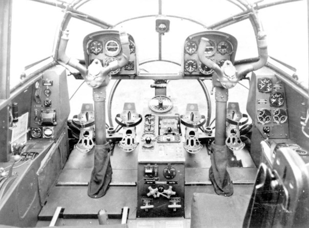
The Skyknight was a solidly built aircraft with a conventional construction. It featured a very wide, monocoque fuselage with folding, mid level, two spar wings. The front of the aircraft contained the search radar or electronic warfare equipment, and the armament, all enclosed in a fiberglass cone. The engines were contained in low slung nacelles within the fuselage, behind which were the airbrakes. At the rear of the aircraft was a conventional stabilizer configuration, with a tail warning radar at the very back of the aircraft. The aircraft had a fully retractable tricycle landing gear arrangement with a deployable tailwheel to prevent tail strikes.

The wings of the aircraft were of conventional construction, though it saw an early use of hydraulically boosted control surfaces. Combined with a set of spoilerons added to the production series of the aircraft, its roll rate was excellent and maneuverability was retained at high speeds. With the fuselage air brakes allowing for the pilot to prevent overshooting a targeted aircraft, or avoiding overspeed, the plane was remarkably controllable in all aspects of flight. They were designed to fold just beyond the outboard pylons.
The final engine of the aircraft was the Westinghouse J34-WE-36. It produced up to 3,400 lbs (1542 kg) of thrust, leaving the aircraft fairly underpowered. Attempts to re-engineer the aircraft were canceled when the J46 never became available. The J34 was a development of the J30, a WWII era jet engine, and was largely obsolete before entering service due to the rapid strides in turbine development after the Second World War. The engine was an axial compressed turbo jet, with 11 compressor stages, and two turbines. In its early service, it was fairly unreliable and dangerous, as the turbines could break and send their blades through the fuselage, into the second engine. Armored deflectors were thus installed early in its military service. The engine ran on 115/145 octane AVGAS, and not jet fuel, a feature which seriously highlighted its obsolescence in later years.

The Westinghouse AN/APQ-35 radar suite comprised three self contained radar units, being the X-band AN/APS-21 Search radar, AN/APG-26 gun laying radar, and AN/APS-28 tail warning radar. The search radar was by far the largest unit and presented a maximum instrumented range of 200 nautical miles for ground contacts. In airborne use, it could detect targets out to a range of about 120 nautical miles. Its scan area could be adjusted in terms of elevation, and had an adjustable horizontal search angle between 30 and 170 degrees. The search radar sat in tandem with the gun laying radar, with the smaller system ahead of the main unit. The gun laying radar had a maximum range of 4000 yards (3657 m) and was activated by aiming the search radar onto the target and engaging the lock feature. The smaller radar would then automatically track the locked target and adjust the aircraft’s gunsight to give an accurate lead. The tail warning radar had a range of 3 nautical miles and was fixed. The console had three scopes, being a plan position indicator scope, an azimuth scope that gave directional guidance toward the target, and a tail warning scope. Long range target information was displayed on a large plan position indicator scope which was used exclusively by the search radar, while the azimuth scope was shared with the gun laying radar and used to guide the pilot on the final approach to the target.
On the electronic warfare model, the radar suite was replaced by a collection of radio emission monitoring equipment, jammers, and countermeasure dispensers. The original EW suite consisted of an APR-13 panoramic surveillance receiver, replaced in the early sixties with the ALR-8, which included a APA-69A direction finder, and an ALA-3 pulse analyzer. The direction finder and the receiver each had their own console and were used to track and classify actively emitting radar systems. The ALR-8 could monitor most of the Soviet, and Soviet derived, radar systems of its day. This was done with a pair of oscilloscopes, one circular in the case of the panoramic indicator, the other linear in the case of the pulse analyzer, and a direct audio output of the radar emission. These gave the direction and pulse width of the radar system respectively, while the audio output could also be used to identify the pulse width and type of radar system. Each had their own distinctive tone, occasionally allowing for easy classification. A constant pulse rate indicated a fire control type system either directing a SAM or anti-aircraft gun batteries.

These systems were seriously overhauled with the Super Whale upgrade under AFC 199. This included a panoramic ULA-2 indicator console which displayed the directions of all emitting radars, and no longer required the ECMO to manually search frequencies. Defensive upgrades included an APR-33 fire control monitor receiver and an ALR-2 missile launch warning receiver. These upgrades automated much of the ECMO’s workload, and allowed for the aircraft to perform missile warning duties while also investigating radar emissions.
Originally, the aircraft was only equipped with a pair of ALR-2 200 watt jammers, which were acceptable through the 1950’s, but totally inadequate for use over Vietnam. They were typically supplemented by outboard jammer pods and countermeasure dispensers. They often carried an ALQ-31 pod that could fit two jammers, which were typically configured to jam the early warning radars used to provide GCI for MiGs, and fire control radars for anti-aircraft batteries. The other major EW tool was the ALE-2 chaff dispenser, which could be used to create metallic, radar reflecting clouds of aluminum strips. Other avionics included VHF radio communication systems, a UHF radio, a VHF beacon homing receiver, a radio altimeter, and a radio compass. These systems were upgraded throughout the Skyknight’s long career, and new systems, like equipment to use the Tactical Air Navigation System, were added.
The Skyknight’s armament consisted originally of four Hispano Suiza M2 20mm cannons with 200 rounds carried for each weapon. The pilot was provided with a radar directed Mk. 20 Mod. 0 gunsight which could provide automatic targeting for a locked target. On electronic warfare variants of the aircraft, the armament was reduced to two weapons, retained for balance and self defense purposes.
A variety of ordnance could be carried on the outer pylons, being unguided bombs up to a weight of 2000 lbs (907 kg) per pylon. The 11.75” ‘Tiny Tim” rocket could also be mounted, though it is unlikely they were ever used, as only a handful of ground attack missions were carried out with this aircraft near the end of the Korean war, and only with unguided bombs. The pylons were otherwise used only for carrying 150, or 300 gallon fuel tanks (567, 1135 liters), in addition to the electronic warfare equipment described above.
The Skyknight featured more creature comforts than most other navy fighters by the time of its design. It was air-conditioned, its floors were carpeted, and an electric cigarette lighter was installed in the instrument panel, with ashtrays at the crew’s elbows. It was perhaps the only fighter aircraft to be equipped with a built-in cigarette lighter. However, it was not retained on the EF-10 and the engineers at Douglas removed it when they were updating the instrument panels. Both crewmembers were provided with urinals in the form of relief tubes for use on long flights.

The escape system consisted of a chute positioned between the crewmen, and at its end was a panel which would be ejected by means of explosive bolts. The crew would then use a bar over the opening, at the rear of the cockpit, to hurdle themselves down the chute and clear the plane. It was effective, though it meant that one could not safely bail out of the aircraft below 2000 ft. Crewmen who ditched the aircraft were to escape via the roof panel, which also doubled as the means to enter and exit the plane.
Conclusion

In spite of failing in its original goal almost completely, the Skyknight’s career in the Marine Corps saw it become the unsung hero of two wars and earn the respect of its crews. It seems almost impossible that an ungainly nightfighter rejected for its original use could have ever brought down cutting edge MiG’s, made the Air Force’s B-29’s untouchable, or claim the night skies over North Korea for its own. Yet in the end, the Marine’s made due, and ‘Willy the Whale’ became one of the most successful fighters in the theater. Beyond this shocking combat debut, it almost effortlessly transitioned into an entirely different role, surveilling radar systems and providing electronic support for US forces in the technological cat-and-mouse race over Vietnam. Developed in an age when planes had their operational life spans measured in months, the Marine Corps flew the Skyknight for almost twenty years, a testament to its ruggedness and versatility.
F3D-2 |
Specification |
|---|---|
| Engine | Westinghouse J36-WE-36 |
| Engine Maximum thrust | 3,400 lbs (1542 kg) |
| Fighter weight internal stores only | 24,614 lbs (11,164 kg) |
| Fighter with 2 x 150 gal tanks | 26,731 lbs (12129 kg) |
| empty weight | 14,898 lbs (6757 kg) |
| Combat Range [with external fuel] | 1,195 nmi |
| Combat Range [internal stores] | 995 nmi |
| Maximum Speed | 426 kts @ 15,000 ft (4572 m) |
| Cruising Speed | 395 kts |
| Combat Ceiling | 35,000 ft (10,668 m) |
| Armament | 4x 20 mm Hispano Suiza M2 cannon |
| Crew | 1x Pilot
1x Radar Operator |
| Length | 45′ 5″ (13.84 m) |
| Height | 16′ 1″ (4.9 m) |
| Wingspan | 50′ (15.24 m) |
| Wing Area | 400 sq.ft (37.16 m2) |
Variants
F3D-1 (F-10A): First production version, J34-WE-34 engines. 28 built.
F3D-2 (F-10B): Improved, final production model. J34-WE-36 engines, lock on capability, General Electric G-3 autopilot, wing spoilers. 237 Built, final aircraft built in March of 1953.
F3D-1M: Sparrow missile testbed.
F3D-2M (MF-10B): Four missile hardpoints, no cannons. Brief service life. 16 converted from F3D-2s.
F3D-2Q (EF-10B): Electronic Warfare Aircraft. 35 Converted from F3D-2.
F3D-2T: Night fighter trainer. 5 converted.
F3D-3: Proposal, swept wing night fighter with J46-WE-3 engines.
Illustrations


Credits
- Article written by Henry H.
- Edited by Stan L.
- Ported by Henry H.
- Illustrated by Hansclaw
Sources:
Primary:
“Eyes In the Night”. Naval Aviation News. V33-34 1952-1953.
Pilot’s Handbook Navy Model F3D-2 Aircraft. Secretary of the Air Force and the Chief Bureau of Aeronautics. 15, July 1952.
NATOPS Flight Manual Navy Model EF-10B Aircraft. Chief of Naval Operations. 1 April 1969.
Night Fighters Over Korea. G.G. O’Rourke with E.T. Woolridge. Naval Institute Press.
Standard Aircraft Characteristics F3D-2 “Skyknight”. 15 February 1952.
Secondary Sources
F-3D/EF-10 Skyknight Units of the Korean and Vietnam Wars. Joe Copalman. Osprey Publishing. 2022.
F-105 Wild Weasel vs SA-2 “Guideline” SAM. Peter Davies. Osprey. 2011.
All Hands. No. 648-658. 1971.
Naval Fighters Number Four Douglas F3D Skyknight. S. Ginter.
Korean Air War Sabres, MiGs and Meteors 1950-53. Michael Napier. Osprey. 2021.
Naval Aviation News, Obituary Heidemann, Jan-Feb. 1992.
Skyknight. R.E. Williams. Naval Aviation News. 1983.
Into the Jet Age: Conflict and Change in Naval Aviation , 1945-1975. E.T. Wooldridge. Naval Institute Press. 1995.
A History of Marine Fighter Attack Squadron 531. Colonel Charles J. Quilter II and Captain John C. Chapin. History and Museums Division Headquarters, US Marine Corps. 2001.
US Marines in Vietnam High Mobility and Standdown 1969. Charles R. Smith. 1988.
Sparks over Vietnam The EB-66 and the Early Struggle of Tactical Electronic Warfare. Captain Gilles Van Nederveen. College of Aerospace Doctrine, Research and education. 2000.
Aircraft Carriers a History of Carrier Aviation and its Influence on World Events Volume II 1946-2005. Norman Polmar. Potomac Books. 1969.