Germany (1937) Rocket Powered Aircraft – 1 Prototype Built
For many years artists often imagined that the He 176 would have looked something like this. [luft46.com]Prior to, and during the war, the German aviation industry developed a series of operational and prototype aircraft designs. Among the leading new technologies, rocket-powered aircraft were being developed. The concept was initially tested prior to the war on a smaller scale, including limited theoretical tests and prototyping. But further development would lead to the creation of the first rocket-powered aircraft known as the He 176. While it wasn’t accepted for service, it proved that such a concept was feasible and set the stage for the later Me 163 rocket-powered aircraft.
History of Rocket Engine Development in Germany
Following the end of the Great War, Germany was forbidden to have an Air Force. This also included the development of aircraft designs, though this did not stop the Germans from experimenting with new aviation technology. One such new technology was rocket propulsion. One of the first such flights using rocket propulsion occurred in June of 1928, when aviation enthusiast Fritz Stramer took to the sky his rocket-powered glider. Another pioneer in rocket-powered flight occurred at the end of September 1929. A pilot named Fritz von Opel managed to take to the sky in his rocket-powered glider, named Ente (Duck). Von Opel was assisted by another prominent aircraft designer Alexander Martin Lippisch. While technically speaking these were not real rocket-powered flights, given that these gliders did not take to the sky using purely the rocket engine but were towed to altitude. Nevertheless, these flights showed that flight using rocket engines was possible.
Von Opel experimental take-off using a rocket propulsion. [L. Warsitz The First Jet Pilot]Over the following years, Lippisch became quite interested in rocket technology and would join the Deutsche Forschungsinstitut DFS, where he worked as an engineer. There, he developed a series of new glider designs, like the DFS 40. This work would eventually lead to the creation of the Me 163 rocket-powered aircraft. The Junkers Aircraft company also was interested in rocket development as they built and tested rocket take-off boosters. One such engine was ground tested in 1936.
Another stepping stone in rocketry research was the work of Wernher von Braun. In 1932 and 1934 von Braun managed to successfully launch two rockets using liquid-fuel rocket engines. In 1935 he managed to come into contact with Dr. Ernst Heinkel 1935. After von Braun presented his work, Dr. Ernst was highly impressed and promised to provide von Braun with any assistance in his work. For this, he appointed a young and energetic aircraft engineer named Walter Wenzelunzel to assist von Braun. In order to properly test the installation of rocket engines in aircraft designs, a special test center was established at Kummersdorf in 1936.
The He 112 prior to the start of testing with the von Broun rocket engine. [luft46.com]Dr. Ernst supplied this research team with a few He 112 airframes. The first He 112 was used for ground testing. For this reason, its fuselage was retained while its wings and the original engine were removed. The rocket engine, which ran on a combination of liquid oxygen and alcohol, would be placed in the rear of the fuselage, with the engine nozzle being placed just beneath the tail unit. Von Braun’s team installed the oxygen tanks in front of the cockpit, with the alcohol tank behind the pilot seat. The engine (the sources do not specify its precise designation) could provide a thrust of 1,000 kg (2,200 lb) with an endurance of 30 seconds. During the testing the engine exploded, destroying the aircraft in the process.
Despite this setback, the project went on. By this time, German Army Officials were becoming interested in the project. In order to maintain its secrecy, von Braun and his team were instructed to find a remote auxiliary airfield where these tests could continue to be conducted away from prying eyes. The team, wanting to be close to Berlin, chose a small field at Neuhardenberg, which was covered on most sides by dense forest. Temporary housing, cabins, and tents were quickly set up in 1937 and the work could finally go on.
In 1937 von Braun began close cooperation with another enthusiast of rocket engine development, Helmuth Walter. This cooperation was partly initiated by the German Air Ministry (Reichsluftfahrtministerium RLM) who intended to use the rocket engines for other proposals, like assistance during take-offs. Walter was a young scientist who was highly interested in rocket propulsion. He managed to obtain military funding, which greatly helped in his work. In 1936 he used a Heinkel He 72 to test this engine. In 1937, he even managed to get the attention of the RLM. The RLM formed a Special Propulsion System department (Sondertriebwerke) with the aim of experimenting with rocket engines in the aircraft industry. While this department was mainly focused on developing rocket engines for short take-off assistance, Walter wanted more than that. He intended to develop a strong rocket engine that could replace the standard piston engines of the day. Walter managed to develop such an engine, named Walter TP-1, which was fueled by the so-called ‘T-Stoff’ (hydrogen peroxide) and ‘Z-Stoff’ (water solution of either calcium or sodium permanganate).
Von Braun requested another aircraft which Henkel provided, this was the He 112 V8 (during these trials it received a slightly changed designation V8/U). The test pilot Erich Warsitz managed to take it to the sky using the aircraft’s original piston engine. Warsitz was a crucial pilot for the German early rocket and jet engine development, being heavily involved in testing and helping with the overall design of both the He 176 and He 178. At about 450 meters Warsitz activated the rocket engine, and during the 30 seconds of the engine burn phase, a speed of nearly 400 km/h (or 460 km/h (286 mph) depending on the source) was reached. Due to the dangerous leakage of the engine, the flight had to be aborted, but otherwise, the flight has deemed a success. This He 112 V8 would be returned to Heinkel, but two more aircraft (H7/U and A-03) would be donated to the rocket research program.
Test pilot Erich Warsitz whose experience and work proved to be vital for both He 176 and 178 aircraft development. [firstjetpilot.com]After this flight, all further tests were conducted using the Walter TP-1 rocket engine. In contrast to the von Braun engine which used alcohol and liquid oxygen as fuel, Walter’s own engine used hydrogen-peroxide and calcium permanganate as a catalyst. This engine was deemed safer too, which is somewhat ironic given the corrosive and volatile fuel. To avoid accidentally coming into contact with the Walter engine fuel, the pilot had to wear a highly protective suit. If exposed to the corrosive fuel, it caused disintegration without actually burning.
More tests were conducted at this location until the end of 1937, when the research was to be moved to Peenemunde. Due to some delays, the tests on the He 112 continued on from April 1938.
Heinkel’s First Rocket-Powered Aircraft
Following the series of tests on the He 112, some officials from the RLM began showing great interest in the prospect of using a rocket-powered aircraft interceptor. It was originally hoped that this aircraft would be capable of vertical, or nearly vertical take-off. When sufficient altitude was reached, the aircraft was then to make a swift dive on its target, firing a volley of its full weapon load. After this attack run, it was simply to glide away once it was out of fuel, to its base of operation.
The work on the project was conducted under a veil of secrecy and began in 1936 at the Heinkel Rostock-Marienehe work. The following year the first drawings of the He 176 V1 (derived from “Versuchsmuster 1” meaning “Experimental Model”) were completed by Hans Regner. Interestingly the designers set a huge task in front of them, by actually trying to reach a blistering speed of 1000 km/h (620 mp/h). An astonishing and difficult feat to achieve with such a novelty design. This set a number of challenges that had to be overcome. One of them was a proper wing design able to withstand the pressure of such high speed. For this reason, it had to be designed to be flat, at only 90 millimeters thick, with very sharp leading edges. This in turn caused further problems, as this design would cause the aircraft to stall at low speeds. In addition, the installation of wing fuel tanks would be difficult.
In order to make the whole design smaller and thus save weight, the pilot had to be placed in a rather unpleasant semi-recumbent position, with his legs stretched out in front and the pilot’s seat reclined. This was also done to help the pilot better cope with the extreme G-forces that he would be subjected to during the extremely high forward acceleration. The fuselage had a very small diameter of only 0.8 meters (2ft 7in) and was specially designed according to the height of the test pilot, Warsitz.
The construction of the first prototype was undertaken at the Heinkel’s aircraft works in Marienehe. Once the aircraft was completed, it was to be transported to Peenemunde. The aircraft’s testing was conducted under great secrecy and was transported there via military escort in June 1938. Just prior to the actual testing, Warsitz was informed by RLM officials that given the experimental nature of the design, and Warsitz’s valued status as an experienced test pilot, he was advised not to fly it. Warsitz, who was heavily involved in the He 176 design, protested to Air Minister (Reichsluftfahrtministerium) Ernst Udet, who gave him permission to undertake the first flight. After this was settled, there were some delays with the assembly and engine adjustment.
The initial tests were undertaken on the ground. Due to unsuitable terrain and lack of a proper towing vehicle, ground testing proved ineffective. So it was decided to use the aircraft’s own engine for these tests, which were conducted at the end of 1938. Using the He 178’s own engine on the ground presented a new problem, namely the rudder could not provide steering during take-off. As the aircraft had no propellers to generate airflow, steering the aircraft using the rudder on take-off was ineffective, thus the only way to maintain the aircraft’s heading was by using the left and right brakes on the main wheels. This was quite dangerous for the pilot and the aircraft, as an imbalanced braking force could potentially lead to an accident. The result of the initial testing showed that some changes to the overall structural design were needed. For this, the Heinkel crews spent the winter of 1939 modifying the He 178.
First Flights
During the Spring of 1939, a series of small test flights were conducted with the He 178. Somewhat unexpectedly, the Heinkel team was visited by an RLM delegation led by Udet himself. After observing the He 178 on the short flight they were quite impressed, but surprisingly for the Heinkel team, Udet forbade any more flights on it. Mostly due to fear for the pilot’s life. After some delays, Warsitz visited Udet in Berlin and filed a plea that the project should go on. Udet finally accepted this and gave a green light.
A military delegation led by Udet observed the He 176’s initial short flight attempts. The man in the white suit is the test pilot Warsitz who is speaking with delegation members about the flight, with Dr. Ernst just behind him. [luft46.com]While the first official flight of the He 176 was to be conducted under the supervision of many RLM officials, feeling that something might go wrong, Erich Warsitz and Heinkel’s team (without the knowledge of Dr. Erns) decided to perform the flight in secrecy. The date for this was set on the 20th of June, 1939. After a rough take-off, the pilot managed to take the He 176 to the sky. Given the small fuel load, the flight lasted around a minute. Overall, the first test flight was deemed a success. The following day, Udet and his delegation visited the site and observed another test flight.
The Fuhrer Inspects the He 176
Hitler during his inspection of the He 176.[L. Warsitz The First Jet Pilot]A couple of days later Warsitz and Heinkel’s team were informed that any further flights were forbidden. The reason was that Hitler himself became interested in the project and wanted to personally see the aircraft. The He 176 was to be transported to the Rechlin Secret Test Center and shown to many high-ranking members of the Luftwaffe. On the 3rd of July 1939, the aircraft was to be demonstrated to a large delegation including Hitler himself. First, a flight of a He 111 equipped with rocket-assisted take-off was shown to Hitler, which greatly impressed him. Another Heinkel innovative design, the He 178 jet-engine powered aircraft, was also present. While it was not yet capable of taking to the sky it was used for ground testing. Next in the line for inspection was the He 176, after a brief examination of its interior by the delegation, the stage was set for it to take to the sky. The flight initially went well, but the pilot miscalculated and shut down the engine too soon. While still at high speed, he began descending rather rapidly. After several attempts to restart the engine, he finally succeeded, just before hitting the ground. The plane took an almost vertical climb of some 50 meters before the pilot regained control and landed it safely. Hitler and his delegation were under the impression that the pilot performed this maneuver intentionally to demonstrate the aircraft’s potential. For his flight, the pilot was awarded 20,000 Reichsmarks.
The End of the Project
After this exhibit, Heinkel’s team tried to prepare the He 176 for reaching speeds up to 1,000 km/h. Structural analysis of the design, on the other hand, showed that this would not be possible. For this reason, preparation for the construction of a second prototype was underway. It was to be powered by a von Braun rocket engine, which suggested that the aircraft could be launched vertically. This was possible thanks to weight reduction efforts sufficient to enable vertical take-off.
Ultimately the whole project would be canceled. The order was given by Adolf Hilter, who insisted that designs that could not enter production in less than a year, be canceled. Despite Heinkel’s attempt to win over Udet’s support, it went nowhere and the project was officially terminated.
The He 176 V1 was disassembled and transported to the Aviation Museum in Berlin to be exhibited. Sadly it would be later on destroyed in one of many Allied bombing raids. The He 176 V2 was almost complete, but its parts were eventually scrapped. The V3 had also been under construction, but was ultimately abandoned in its early stages.
Technical Characteristics
The He 176 was designed as an all-metal, high-wing rocket-powered experimental reconnaissance aircraft. Its fuselage had a simple circular cross-section design. The wings had an asymmetrical profile and were quite thin. During take-off, there was a significant chance of the wingtips contacting the ground, due to the fuselage’s small diameter and extreme vibrations during take-off. To avoid damaging them, Heinkel engineers added a “U” shaped metal bar under each wingtip as a temporary solution. The wings were also initially to act as fuel tanks, but this feature had to be abandoned on the prototype, and fuel was instead stored behind the cockpit. The tail and rudder design was more or less conventional.
To avoid causing damage to the wings during take-off, Heinkel engineers added a “U” shaped metal bar under each wingtip.
The rocket engine chosen for the He 176 was the Walter RI type. It provided thrust ranging between 45 kg to 500 kg (100 to 1,1100 lb) with an endurance of one minute. Due to the weight issues combined with a relatively weak propulsion unit, the desired speed of 1,000 km/h (620 mph) was never reached. The maximum speed reached by this aircraft differs greatly between sources. For example, D. Nešić mentioned that the maximum speed was only 345 kmh, while authors J. R. Smith and A. L. Kay quoted a figure of 700 kmh. Lastly, the test pilot himself in his own logbook mentioned that he managed to reach a speed of 800 kmh (500 mph).
The landing gear consisted of one front smaller wheel, two larger wheels 700 mm in diameter, and one more to the rear. While the front wheel was fixed the remaining three were completely retractable.
The He 176 during take-off [L. Warsitz The First Jet Pilot]The cockpit provided the pilot with an excellent forward view and was made of plexiglass. Given the experimental nature of this aircraft, great attention was given to pilot safety. As in case of emergency, bailing out of the fast-moving and cramped aircraft was almost impossible. Heinkel engineers designed the entire cockpit section to be jettisonable. The cockpit assembly was connected to the fuselage by four locks which were equipped with small explosive charges. When the pilot was jettisoned from the fuselage his parachute would open automatically and allow him to land safely. This system was tested by using a wooden cockpit containing a dummy pilot. This trial cockpit was then taken to the sky by a He 111 and at sufficient height, it was released. The parachute opened without an issue and it landed on the ground intact. The results of the dummy pilot showed that this system was safe if the cockpit landed on soft ground.
The small size of the cockpit prevented the use of a standard instrument panel, as it would severely affect the pilot’s forward visibility. Instead, the instruments were placed to the left and the right of the pilot. Interestingly, while Heinkel did not intend to arm the aircraft, RLM officials insisted that two machine gun ports be placed beside the pilot. Due to the cramped cockpit interior, the two machine guns had to be placed where the pilots’ side controls were positioned. As this would cause delays and much-needed redesign work, the Heinkel engineers simply placed machine gun ports (without the actual machine guns equipped) and kept the original control units in place. The RLM officials, when visiting the work, were told that these were just temporary measures.
The Only Photograph
The real He 176 was quite different in design. [luft46.com]Given the secretive nature of the project, RLM officials effectively gathered all films and photos for themselves. All persons involved in the project were also forbidden from taking any pictures. At the war’s end, the Soviets either destroyed or captured these and their final fate is unknown. Sometime after the war, many artists attempted to produce sketches of how the He 176 may have looked. These greatly differed from the original design, but given the lack of information and general obscurity of the He 176, this is understandable.
Conclusion
The He 176 project arose as a collaboration of several different parties. It was heavily influenced by rocket engine testing and development done by von Braun and Walter. Heinkel Flugzeugwerke provided the necessary resources and production capabilities, while test pilot Erich Warsitz provided valuable feedback which guided necessary changes and improvements to the design.
It was a novel idea to use rockets to power aircraft, which offered numerous advantages, such as reaching high speed and altitude very quickly. Given that this project was more or less a Heinkel private venture in the development of new technologies it likewise did not find a place in German military service. It, however, did set the stage for future designs like the Me 163, which actually saw some combat during the war.
He 176 Specifications
Wingspans
4 m / 13 ft 1 in
Length
5 m / 16 ft 4 in
Height
1.4 m / 4 ft 7 in
Wing Area
8 m² / 53 ft²
Engine
Walter RI rocket engine
Empty Weight
1,570 kg / 3,455lbs
Maximum Takeoff Weight
2,000 kg / 4,400 lbs
Maximum Speed
700 km/h / 435 mph
Endurance flight Range
60 seconds
Crew
One Pilot
Armament
None
Gallery
Illustration by Godzilla
Credits
Written by Marko P.
Edited by Henry H. & Ed J.
Illustration by Godzilla
Sources
D. Nešić (2008), Naoružanje Drugog Svetskog Rata Nemačka Beograd
M. Griehl (2012) X-Planes German Luftwaffe Prototypes 1930-1945, Frontline Book
D. Mondey (2006). The Hamlyn Concise Guide To Axis Aircraft OF World War II, Bounty Books.
D. Donald (1998) German Aircraft Of World War II, Blitz Publisher
J. R Smith and A. L. Kay (1972) German Aircraft of the Second World War, Putnam
Jean-Denis G.G. Lepage (2009), Aircraft Of The Luftwaffe 1935-1945, McFarland & Company Inc
L. Warsitz (2008) The First Jet Pilot The Story of German Test Pilot Erich Warsitz Pen and Sword Aviation
Germany (1943) Experimental Circular Wing Aircraft – 1 Prototype Built
The unusual Sack AS-6 circular-wing aircraft [falkeeins.blogspot.com]In the history of aviation there were many designers who had ambitious ideas and concepts for new designs, but never had the chance to bring their ideas to fruition. On the other hand, there were those who had radical or even completely impractical designs that did manage, at least to some extent, to be built. Germany had a fair share of such individuals, especially during the later stages of the Second World War. These designers may have proposed their projects out of desperation to save their country or in fear of being sent to the front. There were also those that were simply enthusiasts in aircraft development but lacked a better understanding of how aerodynamics actually work. One such person was Arthur Sack (1900-1964), who prior to the war came up with the idea of building a circular-wing aircraft known simply as the Sack AS-6.
History
Prior to the war, Germans were prohibited from developing and building military aircraft. The Germans simply bypassed this prohibition by instead focusing on gliders, but also on civilian aircraft which if needed would be quickly converted for military use and conducted secret experiments. They especially took great care in the development and investment of manned gliders, but also scale model-building competitions and organizations. While this may seem like a waste of time and money, it actually helped gain initial and valuable experience in aircraft development which proved vital for the later Luftwaffe.
One such model competition was the National Contest of Aero Models with combustion engines, held in late June 1939 at Leipzig-Mockau. Here, aviation enthusiast Arthur Sack presented his model of an unusually circular-wing-shaped aircraft named AS-1. It is sadly unclear why Sack pursued the design of such an unusual aircraft design. Due to engine problems, the AS-1 was unable to take off from the ground, so the small model had to be launched by hand instead. The Air Minister (Reichsluftfahrtministerium RLM) Ernst Udet, who was present at the event, seemed to be impressed with this design and advised Sack to continue its development.
Arthur Sack and his AS-1 model. [lvz.de]Thanks to financial support from the RLM, Sack was able to proceed with the development and even the construction of a few scale models, a process that lasted some three years. In 1943 he submitted a fully operational model SA-5 to the RLM. The presentation went well for Sack and the RLM commission provided the necessary funds for the construction of a fully operational prototype. Interestingly, at some point Sack came into contact with another unusual aircraft designer Dr. Alexander Lippisch. While not completely clear, it appears that Sack received some design tips from Lippisch, to better improved his work.
With the order secured, Sack initiated the construction of a prototype. He named this aircraft the AS-6 V1 (Versuchs – version). As he had no proper workshop to build the aircraft himself, the glider manufacturer Mitteldeutsche Metallwerke was tasked with this instead. The initial work for the assembly of the aircraft began in the autumn of 1943. It took nearly half a year to complete the working prototype. Interestingly, due to the general shortage of materials, the AS-6 was constructed by utilizing a considerable amount of salvaged components from other damaged aircraft. For example, the cockpit canopy and parts of the interior were taken from a Bf 109B. Once the prototype was ready, it was allocated to the Luftwaffe for initial tests in early 1944.
AS-6 side view. [lvz.de]
Technical Characteristics
A good view of the AS-6 internal wooden frame construction.[all-aero.com]The AS-6 was designed as an experimental prototype to test the idea of using circular-wing design. Sadly, this aircraft is quite obscure and poorly documented so not much is known about its overall design. It was a single-seater aircraft that was mostly built out of wood. It did not have a classical fuselage, instead, the majority of the aircraft consisted of two large circular wings. The internal design is more or less conventional with a wooden construction frame being covered with canvas. Two large elevators were installed on the rear of the wings. The tail assembly is a conventional design as well, consisting of one vertical stabilizer and two horizontal stabilizers.
The AS-6 rearview. The two elevators were too small, poorly designed, and did not provide adequate control during initially limited test flights. [all-aero.com]The AS-6 was powered by an Argus As 10C-3 engine, which ultimately proved to be inadequate [all-aero.com]The AS-6 was powered by a 240 hp Argus As 10C-3 engine driving a two-blade wooden propeller. The engine was housed in a metal frame, which was then bolted to the AS-6 fuselage. The engine was salvaged from a Bf 108 aircraft.
The cockpit canopy and its interior, as already mentioned, were taken from a Bf 109B. The cockpit was slightly elevated above the fuselage and provided the pilot with an excellent all-around view. The landing gear was also salvaged from a Bf 109B, but in the case of the AS-6, it was fixed. Initially, a landing skid was used on the rear, which was later replaced with a landing wheel instead.
The canopy and landing gear was taken from a damaged Bf 109 aircraft [ufxufo.org]
Testing the Prototype
Initial evaluation tests of the AS-6 prototype were conducted at the Luftwaffe Brandis Airbase. The flight tests were conducted by Rolf Baltabol Junkers test pilot. While several short take-offs were made, there were no attempts to actually take the aircraft to the sky. The test pilot noted that the aircraft had an overall poor design and was difficult to control. He urged that the control surfaces and rudder be completely redesigned. The engine was also deemed too weak. During the last short take-off, one of the two landing gear assemblies was damaged.
The AS-6, following its unsuccessful start, spent several weeks in repairs and received a number of modifications in an attempt to improve its performance. These included adding an additional 70 kg of weight to the rear, installation of brakes taken from a Ju 88, and repositioning the landing wheels to the rear by about 20 cm. Sack proposed moving the landing wheels further back, but the test pilot Rolf simply refused to fly it if this change was implemented. He argued that placing the landing gear to the rear would imbalance the aircraft potentially leading to tipping forward during a take-off. For this reason, the modification was not implemented. While the engine was underpowered, there were simply no alternatives available at that time.
The AS-6 during testing [falkeeins.blogspot.com]The next test was scheduled for April 1944. During these tests, Rolf tried to take it to the sky, but failed again to do so. This time it was noted that the wings were simply too short. Further tests were canceled, the AS-6 was to await more modifications, and was to be tested in a wind tunnel; if possible with a completely new engine.
The fate of the AS-6
Following the unsuccessful testing, the AS-6 was stored at the Brandis airfield. In the summer of 1944, this airfield became the main operational base for the experimental Me 163 rocket-powered aircraft. The pilots of the I./JG 400 (charged with testing the Me 163) found the AS-6. One of its pilots, Franz Rossle, expressed a desire to attempt flying the unusual plane. But when the ground crew was preparing the aircraft for take-off, one of its landing gear units simply broke due to rough terrain, effectively preventing the test flight to be conducted. After this, it was once again stored at Brandis. It would remain there until early 1945 when it was lost in an Allied bombing raid.
The AS-7 project
While not clear when (possibly during early 1945), Sack approached Messerschmitt company with a proposal to use his circular-wing design on the Bf 109K-4 aircraft. The aircraft marked as SA-7 would be powered by a DB 605 2,000 hp engine. Fitted with circular wings it was theorized that it would be capable of carrying more armament inside the wings. It is believed (but not clear) that Messerschmitt was interested in this proposal and designated the project Me 600. Due to the war’s end, nothing really came from this project.
Conclusion
While certainly an unusual and interesting design, due to poor quality and salvaged materials used during its construction, the AS-6 performed poorly and never actually achieved flight. We will never know if the AS-6 circular-wing design offered any major advantage over more conventional wing designs. It appears that Arthur Sack did not continue with his idea after the war and passed away in the mid-1960’s. While his work was never implemented in mass production, his unusual design was often mistakenly taken as some advanced and secret German World War II project, which ironically, it never was.
Germany (1944) Rocket-Powered Interceptor Prototype – 1 Built
The Me 163D prototype [luftwaffephotos.com]The Me 163 showed to have great potential as a fast rocket-powered interceptor, but its design had some shortcomings. These included a limited view from the cockpit, lacking of landing gear, increased fuel storage, etc. The German companies Messerschmitt and later Junkers tried to resolve this by implementing a number of improvements to its design leading to the Me 163D of which only a few prototypes were built given the late start of the program.
History
The Me 163 small size, while reducing the overall cost of the aircraft, enforced limitation of the fuel that could be stored inside which in turn led to a limited operational powered flight time of fewer than 8 minutes. In combat operations, this proved to be insufficient but no auxiliary tanks could be added to the Me 163 wings not inside of it. Another issue was the lack of proper landing gear. The Me 163 was instead forced to use a two-wheel dolly. Once the aircraft was in the air, the dolly was jettisoned. On occasion, there were accidents regarding this system when for example the dolly refused to be detached from the aircraft or even worse when it bounced off the ground and hit the aircraft from below. On the landing, the Me 163 were to use a simple retractable landing skid, placed beneath the fuselage. After landing the aircraft was immobile and essentially an easy target for enemy crafts. For this reason, a normal retracting landing gear unit was desirable but once again due to Me 163 small size impossible to install.
To redress the previously mentioned issues engineers at Messerschmitt began working on an improved version named Me 163C. It incorporated a longer fuselage, extended cockpit, having an engine with two combustion chambers, and other modifications. The work on this version was rather slow and by war end not much was done on it besides a few incomplete airframes.
Illustration of a Me 163C aircraft, which was to replace the Me 163B. [walterwerke.co.uk]One or two Me 163B prototypes had their fuselage extended in order if such modification was possible. [walterwerke.co.uk]Parallel with the Me 163C development another project was carried out in early 1944 once again by Messerschmitt. This project was initially designated as Me 163D and was to have substantial numbers of improvements mostly regarding the overall shape of the aircraft, engine use, weaponry etc. For testing this new concept of substantially extending the aircraft fuselage if it was feasible at all. One or two (depending on the source) Me 163 (BV13 and BV18) was to be experimentally modified with an extended fuselage. In addition, experimental landing gear was also to be added. The testing of this rebuilt aircraft proved to be feasible and so the work on a fully built prototype began in earnest.
Name
The Me 163D project, due to Messerschmitt being simply overburdened with the Me 262 production, would instead be given to Junkers company. Once in their hands, the project was renamed Ju 248. The Me 163D obviously had an identity crisis as in late 1944 it was once again given back to Messerschmitt. Once back to its original designers, the project once again changed its name, this time to Me 263. As all three designations are basically correct for this aircraft, this article will use the original Me 163D designation for the sake of simplicity and to avoid any possible confusion.
First Prototype
Despite being originally designed by Messerschmitt, it was actually assembled in Junkers factories sometime during August 1944 or in early 1945 (the sources are not clear here). After that it would be returned to Messerschmitt where it was planned to examine and test its overall performance. While it was intended to have an increase in fuel capacity and an improved engine, the first prototype had actually no engine installed at that time. The Me 163D V1 (DV-PA) prototype was also provided with a new retractable tricycle landing gear which was to help with the mobility during the ground drive.
Given that no engine was fitted to the Me 163D, first flight testing was done as a glider, in late 1944. After these were conducted the prototype was in a series of wind-tunnel testings. The results of these two test trials (flight and wind tunnel) showed that the Me 163D was not capable of safely achieving dive speeds that were greater than its normal flight speed. In this regard, it was inferior to the original Me 163 aircraft which could achieve extensive dive speed but still managed to preserve good flight controls. The Messerschmitt engineers at this phase even considered redesigning the rear tail unit, but nothing came of it. The tricycle landing gear units did not offer good mobility on the ground, this was mainly due to it being too narrow. The Germans had plans to test using a parachute that was to be released during landing to help reduce the need for a long airfield. If this was tested or even installed on a Me 163D is unknown.
Technical characteristics
The Me 163D like its predecessor was designed as a high-speed, rocket-powered, swept-wing tailless aircraft. Given its experimental nature and its late development into the war, not much is known about its precise technical characteristics. Its overall construction would probably be similar to the previous versions, with a fuselage being built of metal and wooden wings.
The semi-monocoque construction fuselage was longer and was now 7.88 m ( 25 ft 10 in) compared to the original 5.84 m (9 ft 2 in) length. It had a good overall aerodynamic shape. The wings were swept to the back at a 19° angle, compared to the Me 163B 23.3° angle.
The Me 163D like its predecessor had wings that were swept to the back at a 19° angle. The fuselage had an excellent aerodynamic shape. [forum.warthunder.com]The pilot cockpit received a new ‘bubble-shaped canopy. This provided the pilot with a much greater field of view. Given that it was intended to operate at great heights, the Me 163 D cockpit was to be pressurized and for this was bolted to the fuselage.
The Me 163D received a much better canopy which offered a much better all-around view. It was also completely pressurized so that the pilot could effectively fly it, on great heights. [forum.warthunder.com]Interior of the Me 163D pilot cockpit. [forum.warthunder.com]The Me 163D was to be powered by an improved Walter 109-509C rocket engine. It was provided by two combustion chambers. While the sources are not clear if this engine was ever installed in the Me 163D, the estimated maximum speed was noted to be 950 km/h (590 mph) or up to 1,000 km/h (620 mph) depending on the source. It should also provide more economical consumption of fuel providing an operational range of some 160-220 km (100-140 mile) once again depending on the source. The operational flight endurance was increased from 7 minutes and 30 seconds to 15 minutes.
To overcome the previous Me 163B version’s lack of proper landing gear, the Me 163D was provided with the retractable tricycle landing gear. It consisted of a forward smaller and two larger wheels in the rear, just below the wing roots. All three of these retracted to the rear into the fuselage.
The fuel load consisted of 1040 liters (229 gallons) of T-Stoff and 492 liters of C-Stoff. The Me 163 was notorious for having only a limited endurance flight ofOnce the fuel was spent the pilots were to simply glide the aircraft back to the base.
The armament consisted of two 30 mm (1.18 in) MK 108 cannons, which were placed in the wing roots. Depending on the source the ammunition storage for each cannon ranged between 40 to 75 rounds.
Production
It is often mentioned in the sources that one complete and one partially complete prototype were built, by the war’s end. According to M. Griehl (Jet Planes of the Third Reich) on the other hand, mentioned that at least three prototypes were built with less than 20 aircraft being in various states of construction when these were captured by the Allies in 1945.
Service
The limited operational test use of the Me 163D and the German plans for it is not clear. Once again depending on the sources, there are mostly two versions. It appears that despite some faults in its design the Germans were willing to proceed with its further development. Given the end of the war, it should not be surprising that this was ever achieved. In another version, the work on the Me163D after some testing flight in February 1945 was officially terminated by the Luftwaffe officials. Mostly due to the fact that production of its unique and dangerous fuel is no longer possible.
The fate of these aircraft is not clear, given either information that these were either destroyed or captured by the Soviets. The latter option seems more likely as some sources suggest that the Soviets based on the Me 163D after the war developed their own version of it, the I-270. The project led nowhere and it would be abandoned.
Me 163D V1 – Completed prototype
Me 163D V2 – Incomplete second prototype
Me 163D V3 – Possible third prototype being built with additional 18 airframes
Conclusion
Given its experimental nature and its late introduction, it is quite difficult to make the final decision on the general properties of this aircraft. While it introduced some improvements in comparison to the previous version it also had issues regarding its reaching speed during dive flights. Despite offering the Germans a relatively cheap aircraft the whole Me 163 project by 1945 was essentially over given the general impossibility of production of its unique fuel. Nevertheless despite its downsides, the Me 163 whole series was certainly an interesting concept that had some merits that unfortunately for the Germans were never completely implemented.
Me 163D V1 Specifications
Wingspans
31 ft 2 in / 9.5 m
Length
25 ft 10 in / 7.88m
Height
ft in / 3.17 m
Wing Area
192.6 ft² / 17.91 m²
Engine
HWL 509 rocket engine
Empty Weight
4,400 lbs / 2,000 kg
Maximum Takeoff Weight
11,660 lbs / 5.300 kg
Maximum Speed
590 mph / 950 km/h
Operational range
100 mil / 160 km
Engine endurance
15 minutes
Maximum Service Ceiling
52,480 ft / 16,000 m
Crew
One pilot
Armament
Two 30 mm MK108 cannons
Gallery
Artist Conception of the Me 163C – by Carpaticus
Artist Conception of the Me 263 – by Carpaticus
Credits
Written by Marko P.
Edited by Henry H. & Ed J.
Illustrated by Carpaticus
Source:
D. Nešić (2008) Naoružanje Drugog Svetsko Rata-Nemcaka. Beograd.
E. T. Maloney and U. Feist (1968) Messerschmitt Me 163, Fallbrook
M. Emmerling and J. Dressel (1992) Messerschmitt Me 163 “Komet” Vol.II, Schiffer Military History
J.R. Smith and A. L. Kay (1990) German AIrcraft of the Second World War, Putham
Nazi Germany (1944) Rocket Powered Fighter – Around 370 Built
The Me 163B in standard camouflage. Note the brightly colored nose. [militaryimages.net]Following the successful testing of the previous Me 163A series, the Germans began developing a new improved version that was intended for operational use. This would lead to the Me 163B series, which was the first, and last, operational rocket-powered aircraft to be used in active combat. In comparison to its predecessor, the Me 163B offered a number of improvements to its design and shape. By the war’s end, less than 400 aircraft of this type would be built.
History
Work on the second series of the Me 163, which would be built in greater numbers than the experimental A-series, began at the start of September 1941. In comparison to the predecessor, the B-version had a number of modifications. The most obvious change was the completely redesigned fuselage, which was larger and had an overall more aerodynamic shape. Its armament was installed in the wing roots, the engine was replaced with an improved version, and the pilot cockpit was enlarged.
The differences between the Me 163A (on the left) and the main production version are clearly evident here. [acesflyhigh.wordpress.com]
Initial plans for this aircraft were quite ambitious, as Messerschmitt had predicted that the production of four operational prototype aircraft with additional airframes should commence in October 1941. Once the first few prototypes were completed, a small series of 66 aircraft were to follow. The actual responsibility of building these was given to Messerschmitt production plants at Regensburg with assembly at Obertraubling. It was estimated by RLM (Reichsluftfahrtministerium – Ministry of Aviation) officials that, after the first batch of 70 aircraft was built, it would take some 7 months to actually begin mass production of fully operational aircraft.
One of the first few Me 163B prototypes built. [luftwaffephotos.com]As was the case with many German wartime projects, it suffered from delays due to a lack of resources. The work on the initial group of prototypes started only at the end of 1941. Once again, further delays due to the slow delivery of engines postponed production until March of 1942. At this stage, the Germans were replacing the R II 209 rocket engines with the modified RII 211. The new engine used different types of fuel tanks which necessitated the redesign of the fuselage interior. This engine used a combination of T-Stoff and C-Stoff (a mixture of hydrazine hydrate, water, and methanol). As the construction of the Me 163B V1 prototype was approaching completion, it was proposed to switch to the older R II 203 engine to save development time, but this modification was not carried out. The development of the rocket engines was very slow and plagued with many setbacks, especially the limited production of fuel, which eventually led to huge delays in the Me 163 production. Finally, for the Me 163 production aircraft, the improved HWK-509 engine was chosen.
In May 1942, Me 163 B-0 V1 (KE+SX) was completed, minus the engine, and was tested as an unpowered glider. By 1943, it was obvious that Messerschmitt alone could not cope with the wartime demands, so RLM officials decided to bring aboard another aircraft manufacturer. They chose Klemm’s Stuttgart-Boeblingen factory, with a monthly goal of some 30 Me 163 aircraft. Klemm was also tasked with providing additional workers for Messerschmitt. Delays in delivering essential parts, such as weapons, caused setbacks in the Klemm Me 163 production.
Despite the problems with the Me 163 production, a small number of available aircraft were allocated to the Erprobungkommando (EKdo) 16 unit from April 1942 onward.
First Flights by EKdo 16
Once the first prototype was available, it was flight-tested as a glider by Heini Dittmar in late June, or May of 1942, depending on the source. Heini Dittmar had plenty of experience as a test pilot flying the Me 163A aircraft. The BV1 prototype would be, from this point on, mainly used as a training glider aircraft. From this point forward all aircraft built would be transported to Bad Zwischenahn near Oldenburg. Once there, they would be flight-tested by a number of pilots under the command of Karl Voy from EKdo16. This unit, which was formed in April of 1942, had the primary function of testing and evaluating the newly built Me 163 and helping in the development and improvement of its overall design. Another purpose that this unit had to fulfill was the training of new pilots for the Me 163.
An interesting episode in EKdo 16’s history is connected to the well-known German test pilot Hanna Reitsch. After a number of attempts to get permission to flight test the Me 163, she was finally allowed to do so at the end of 1942. Shortly after she took off, the jettisonable takeoff dolly refused to successfully detach from the aircraft, preventing it from using the landing skid. She managed to land the aircraft but was badly wounded and was placed in a hospital for some time. She later requested permission to fly the Me 163 again, but was explicitly rejected and was forbidden from flying it.
In early 1943, this unit was also tasked with testing jet-powered aircraft that were currently in development. These included the Me 262 and the He 280. EKdo 16 began receiving the first operational Me 163Bs only in July, or February of 1943. Due to extensive Allied Air Force activity near EKdo 16’s base of operation, the unit began the process of relocating its aircraft to Anklam. By this time, the unit had some 7 Me 163A and 1 of the B version. Due to poor ground conditions for Me 163 operations, the aircraft was relocated back to Bad Zwischenahn in late August. The delays with the construction of auxiliary support buildings on this airfield meant that crew training could not begin until October 1943. These initial training flights were carried out using two-seater gliders. Due to a lack of C-Stoff fuel, another series of delays impacted progress on training. In November, the Me 163As were used for crew training. In November and later in December, two aircraft were lost in accidents with the loss of life of both pilots.
In the following months, due to a number of factors like slow production, bad weather, and Allied activity, the Me 163 training program progressed at a slow pace. By May 1944, only a small group of fewer than 50 pilots had a chance to fly either the powered or towed versions of the Me 163. Once these were successfully tested, they would be then allocated to the 1./J.G. 400. unit.
The first combat action of the Me 163 was conducted on 14th May 1944, piloted by Major Spate. Amusingly, just prior to the first flight, his Me 163 BV 41 (PK-QL) aircraft was painted in red. This was done by the unit mechanics, who wanted with this small gesture to bring good luck to their pilots. Seeing no harm in it, Major Spate gave instruction that his aircraft be fully fueled and armed. During his flight, he attempted twice to attack Allied bombers but failed to properly engage them. It seems the red paint did not help with the luck.
During May, a number of unsuccessful combat flights with the Me 163 were undertaken. At the end of May, the airfield at Bad Zwischenahn was heavily bombed. During this attack, several Me 163s were damaged. This attack left the airfield at Bad Zwischenahn unusable for some time. To continue the training of pilots, the whole operation was temporarily moved to Brieg on the Oder. As this airfield lacked any proper workshops, the dismantled aircraft could not be assembled again and, for this reason, no test flights were ever carried out from Brieg.
Interestingly, on the 12th and 13th June 1944, three Me 163s from the EKdo 16 were demonstrated to the Japanese and Italian military delegations. As, at that time, EKdo 16 could not provide a fully operational Me 163, these were instead taken from 1./J.G. 400.
On 15th June 1944, the unit was once again back to Bad Zwischenahn. At their disposal, there were 2 prototypes, 7 gliders and 11 fully operational Me 163 aircraft. A few days later, another accident occurred when the towing aircraft lost power to one of its engines. The towed Me 163 was released at some 50 meters of altitude and the pilot was forced to land at a nearby lake. While the aircraft was heavily damaged, the pilot managed to survive.
In July 1944, a second auxiliary unit (Erganzumgsstaffel) was formed. It was also subordinated to the 1./J.G. 400. It had 6 Me 163s, of which only one was equipped with a rocket engine. It was intended to supplement the training of pilots for 1./J.G. 400.
In mid-August 1944, the airfield was once again attacked by Allied bombers. This caused further delays in training operations, until August 23rd. On that day, another accident led to the death of a pilot and the loss of yet another aircraft. Not wanting to waste the parts of the destroyed Me 163, these were collected and then sent to the training school at Fassberg.
At the start of September, Luftwaffe Generalmajor Adolf Galland told EKdo 16’s Commander Hauptmann Thaler, that the unit was to be disbanded and all personnel and equipment were to be relocated to Brandis. While the commanders of EKdo 16 were against such a decision, there was little they could do and, by the end of September, the unit was on its way to Brandis.
An Me 163 from EKdo 16. While some combat flights were undertaken, the primary purpose of this unit was to provide necessary pilot training. [aviationshoppe.com]
Technical Characteristics
The Me 163 was a high-speed, rocket-powered, swept-wing tailless aircraft. Its fuselage was constructed of metal, while the wings were wood. The fuselage could be divided into three sections, the cockpit, the central fuel tanks, and the rear engine compartment. In order to help the ground crew with repairs, the fuselage was specially designed to contain a large number of removable panels. Thanks to this, the replacement of damaged parts or even the whole engine could be done relatively quickly.
The wings were quite simple in design, consisting of two spars covered in 8 mm thick fabric. The Me 163 wings were swept to the rear at a 23.3° angle. At the wing’s trailing edges, ailerons were placed, which the pilot used for pitch and roll. For landings, large hydraulically operated flaps were added on the wings.
In order for the pilot to enter the cockpit, a ladder was placed on the left side of the aircraft. While the cockpit was not pressurized, it could be jettisoned to help the pilot escape the aircraft in case of emergency. Being unpressurized actually placed time limits for how long the pilot could endure without losing consciousness at altitude and during high-speed maneuvers. For this reason, the pilot had to endure altitude chamber training and had a specially designed diet. Despite attempts to improve visibility compared to the previous version, the Me 163B suffered from poor visibility, especially to the rear and in front of the aircraft’s nose.
In order to enter his flight position, the pilot used a small ladder placed on the left side of the aircraft. [acesflyinghigh.wordpress.com]Close-up view of the Me 163 cockpit and instruments. [luftwaffephotos.com]The Me 163 was equipped with various onboard equipment, including a FuG 16 ZE radio transmitter and receiver. In addition, a FuG 25 IFF (identification friend or foe) transmitter and receiver was installed. Given its small size and limited overall weight, the onboard batteries had a limited capacity. In order to provide the necessary power, the Germans simply added a small windmill generator which was placed on the nose of the fuselage.
During its development, the Me 163B was tested with a series of different rocket engines. Ultimately, for the main production version, the HWK (Helmuth Walter Kiel) 109-509A rocket engine was chosen. This had a thrust power ranging from 100 kg (220 lbs) to 1,500 kg (3,300 lbs) or 1,700 kg (3,750 lbs), depending on the source.
The Me 163 initially used a fuel mixture of the T and Z-Stoff. T-Stoff consisted of a mix of hydrogen peroxide with oxyquinoline or phosphate. Z-Stoff was an aqueous solution of calcium permanganate. Z-Stoff would later be replaced with C-Stoff, which was a mix of methyl alcohol, hydrazine hydrate, and water. T-Stoff was stored in one main and two smaller auxiliary tanks. The smaller tanks were placed on both sides of the cockpit. The C-Stoff fuel tanks were placed in the Me 163’s wings. In order to help circulate the fuel, two centrifugal pumps were placed inside the Me 163.
These chemicals were extremely flammable and dangerous to handle and thus required safety procedures to be used properly. Before each flight, the fuel tanks had to be thoroughly washed with water. During refueling, the ground and the aircraft had to be sprayed with large amounts of water. If the safety procedures were not followed, there was a great risk of explosion, which happened on occasion. Due to the volatile nature of the fuel, any harsh landing with fuel still onboard offered a great chance of explosion as well, which led to a number of pilots being lost. Being highly corrosive and deadly to the touch, the maintenance crews and pilots had to wear specially designed protective clothing and gloves. Preserved photographs seem to indicate that these precautions were not always strictly adhered to. Given that the Me 163 operated in late 1944 were shortages of all kinds of equipment and materials were common, this should not come as a surprise. Still, handling the Me 163 fuel without this kind of protection was highly dangerous for the ground maintenance crews.
This Me 163 is in the process of being refueled. [acesflyinghigh.wordpress.com]The fuel load consisted of 1040 liters (229 gallons) of T-Stoff and 492 liters of C-Stoff. The Me 163 was notorious for having only a limited powered flight endurance of 7 minutes and 30 seconds before its fuel reserve was spent. The actual flight could be much longer, however, since at sufficient altitude, the pilot could switch off the engine, and reactivate it as needed. After all rocket fuel had been spent, the pilot would then use the Me 163 as a glider to fly back to its base, or to any nearby German airfield.
The initial armament consisted of two 20 mm MG 151/20 cannons, which were positioned in the wing roots. To increase the firepower these would be replaced with the stronger 30 mm MK 108 cannons. The Me 163B-0 series was armed with the weaker 20mm cannon while the Me 163 B-1 with the stronger 30mm cannon. While the Mk 108 had sufficient firepower to outright destroy or heavily damage enemy aircraft, it was plagued with low velocity. This combined with the extraordinary speed of the Me 163 made engaging targets difficult. For this reason, the Me 163 was tested with some experimental weapon systems. These include the 5.5 cm R4M air-to-air rocket, and the more revolutionary SG 500 Jagdfaust. This weapon consisted of five rockets usually placed under each wing, but on the Me 163 it was actually mounted vertically in the wings. It was provided with an optical sensor that activated its weapon load once it detected shadow, in theory, a shadow of an enemy plane. This was an automated weapon firing mechanism capable of friendly fire if not managed properly. But this situation would be rare given the fact that Me 163 was a short-range and unique interceptor that operated on its own without support from other aircraft.
The Me 163 was armed initially with two MG 151 and later with MK 108 cannons which were placed in the wing roots. The left-wing cannon muzzle brake is visible in this picture. The pilot in this picture is Heini Dittmar was a vital test pilot for the whole Me 163 project. [acesflyinghigh.wordpress.com]The Me 163 utilized an auxiliary landing gear unit. This was mainly done to reduce the overall weight of the aircraft. Take-offs and landings were divided into two phases. For take-off, the Me 163 sat on a simple two-wheel dolly unit. Once at sufficient altitude the dolly was jettisoned from the bottom of the aircraft. On occasion, there were accidents involving this system, when, for example, the dolly refused to release from the aircraft, or even worse, it could bounce off the ground and strike the aircraft from below. Therefore the Germans worked on developing safer types of dollies. On landing, the Me 163 were to use a simple retractable landing skid, placed beneath the fuselage. In addition, to the rear of the aircraft, a small steerable tail wheel was added to help during take-off and landing.
Close-up view of the Me 163 landing skid. [Wiki]The rear wheel was completely steerable and was added to help during take-off and landing. [warbirdphotographs.com]
Once at a sufficient height, the two-wheel dolly would jettison from the aircraft (in the left corner). While in theory, this should work without any issue, in some cases the dolly would simply bounce off the ground and hit the aircraft from below potentially causing damage to it. [luftwaffephotos.com]While this takeoff and landing system offered the desired reduction in weight, it was not without its problems. Besides the issues previously mentioned, after a successful landing, the Me 163 was immobile and vulnerable to possible enemy attacks. To move it across the airfield the Germans designed and built a small specialized aircraft tug, called the Scheuchschlepper, especially for this task.
The Scheuchschlepper is specially designed to either tow or lift the Me 163 aircraft. [warbirdphotographs.com]The Scheuchschlepper essentially fulfilled two roles. Initially, in the three-wheel configuration, it was to tow the Me 163 along the airfield, using its own dolly, to a designated takeoff position on the airfield (upper picture). After the Me 163 returned from a sortie, the Scheuchschlepper rear wheel would be replaced with a tracked platform which supported a cradle that fully supported the entire aircraft at its wing roots, to move the Me 163 for refueling and to be refitted on a takeoff dolly for the next flight. [wiki]
Operational Combat Use
The first operational unit that was to be equipped with the Me 163 was the Staffel of Jagdgeschwader 20./JG 1 located at Bad Zwischenahn. According to initial plans, this unit was to be formed at least by the end of 1943 or in early 1944 depending on the sources. In its inventory, there were some 12 fully operational Me 163 available. In addition, the Germans planned for the Me 163 to be positioned at a series of auxiliary airfields along Allied bomber routes. These would be fully equipped with spare parts, ammunition, and fuel, and positioned close to each other. This way, after an attack run, the Me 163 pilots could simply choose on which airfield to land, knowing that they could resupply without any problems.
But in reality, it took a few more months before the unit was actually officially formed at the start of March 1944. The development of a network of supporting airfields for the Me 163 was also never completed. The unit was by that time being renamed to Jagdgeschwader 1./JG 400 and stationed at Deelen. The commander of the unit was Oberleunant Rober Olejnik. They were relocated to Wittmundhafen as the airfield at Deelen proved unfit for the Me 163 aircraft’s operation.
The unit received its first operational Me 163 on the 10th of March, and seven more were to arrive by late April 1944. Concurrently, pilots were beginning to arrive from the EKdo 16 training unit. More test flights were carried out until mid-March 1944 when they had to be temporarily stopped. The reason for this was the lack of sufficient water supply which was essential for flushing the Me 163 fuel tanks in order to avoid any accidental explosion. To resolve this issue the unit personnel began drilling wells to collect water.
1./JG 400 was at this stage prohibited from making combat flights in order to avoid the attention of the Allies. However, the unit was permitted to conduct live firing trials during flights in order to test the Me 163 weapons systems. While generally successful, during sharp maneuvers at a speed of some 800 km/h, the ammunition belts proved prone to malfunction. While Olejnik suggested using a drum magazine, which was even tested successfully, his idea would not be adopted. On the 21st of April Olejnik had an accident during a forced landing where he spent some time in hospital thereafter.
In April and May, 1./JG 400 took delivery of a group of 10 aircraft, but one had to be returned to Klemm for modifications. That particular aircraft would be destroyed in an Allied bombing raid on Klemm. These were still prototype aircraft of the B pre-production version. The first Me 163B-0 series aircraft began to arrive from May 1944. At this time the Luftwaffe officials were determined to introduce the Me 163 to service. For this reason, the work on testing and experimenting with the Me 163 was stopped in favor of increasing the overall production of the Me 163 B-1.
With the expected increase in production, another unit, 2./J.G.400, was to be formed in May 1944. It was initially to be involved with crucial crew training. At that time, the size of both units was to be increased to 14 instead of 12 operational aircraft.
In July 1944, 1./JG 400 received permission to make combat flights. The Me 163 were then used in several failed attempts to intercept the Allied reconnaissance aircraft that made frequent flights over the base. At the same time, 1./JG 400 and other available Me 163 were being relocated to new positions at Brandis. The original plans to build numerous connected airfields were abandoned in favor of concentrating all available Me 163 in a few selected airfields. For this reason, Brandis would become the main key point for the Me 163 combat operations. It is from there that the Me 163s attempted to intercept a huge Allied air formation of some 766 bombers, supported with over 14 groups of cover fighters. The Me 163 did not engage the Allies probably due to the small number of available aircraft and the heavy fighter cover. By the end of July, the 1./JG 400 had only four operational aircraft out of 16 available.
In mid-August, Me 163s from this unit attacked an Allied B-17 bomber formation. While evading the fighter cover, they managed to heavily damage at least one bomber, killing two crew members. On the 16th of August, five Me 163 attacked a group of B-17s, and even managed to shoot down two of the bombers. The Germans lost one Me 163 during this engagement being hit by an Allied P-51. On the 24th of August, eight Me 163 managed to shoot down three more bombers while successfully evading enemy fighter cover.
While this aircraft managed to fly back to Allied Air Bases in England, the damage inflicted by the Me 163 cannons is evident here. The rear gunner position was completely destroyed while the right tail unit was heavily damaged. [. Ransom and H.H. Cammann Jagdgeschwader 400]On the 8th of September, the Me 163 were officially taken into service. Given the previous success, of destroying 5 enemy bombers with a limited number of available Me 163, attempts were made to increase the number of squadrons with 20 aircraft. This was never achieved, as the Allies destroyed the vital C-Stoff fuel production facility at Kiel in August. On the 11th of September, a single Me 163 attacked and destroyed a lone B-17.
During these initial combat engagements with the Allied bombers, German pilots noticed that the Me 163s armament had a huge flaw. The weapons were difficult to use with the standard attack tactics of the aircraft. This involved getting the Me 163 high above the Allied bombers and then plunging down at them with a dive speed of 885-930 km/h (550-580 mph). Due to its main cannon’s low velocity, and in order to avoid collision with the target, the pilot had only a few seconds available to engage the enemy. This meant that only the highly experienced Me 163 pilot had a chance of hitting the enemy aircraft. The Me 163 also had another flaw, as it could be only used when the weather was clear.
At the end of September 1944, II./JG400 was formed, under the command of Lieutenant Peter Gerth (3/JG 400) and Oberleutnant Franz Woidich (4/JG 400). These units were renamed in November or December 1944 to 5. and 6./JG 400. During this time the 7/JG 400 was also formed, which was stationed at Stettin-Altdamm. In late 1944 II./JG400 was repositioned at Stargard. Few sorties were carried out mostly due to lack of fuel. In November 1944 a Me 163 engaged a British Mosquito, damaging it and forcing its crew to abandon the aircraft.
An Me 163B is engaging Allied B-17 bombers. The Me 163, despite its small number, proved to be a shock to the Allies pilots. Given that they could do little against it when the Me 163 was in its dive attack. [acesflyinghigh.wordpress.com]Bad weather, lack of fuel and the rapid Allied advance on the West and East temporarily stopped all Me 163 combat operations. Combat operations began again in March of 1945. For example on the 16th March, an Me 163 managed to damage another Mosquito on a reconnaissance mission. While the Mosquito pilot managed to fly back to France, he was forced to crash land. A quite interesting Me 163 air victory was achieved on the 10th April 1945 while piloted by Leutnant Fritz Kelb. This aircraft was equipped with the experimental SG 500 Jagdfaust and managed to shoot down a British Lancaster bomber.
In late April I/.J.G.400 would be disbanded and its remaining few operational Me 163 were allocated to the J.G 7. The former I/.J.G.400 commander Wolfgang Spate, flying one of the remaining operational Me 163, managed to destroy 5 additional Allied bombers by the end of the war. The remaining ground personnel from the I/.J.G.400 were dispatched to the East to fight as infantry in Bavaria. There, they allegedly managed to destroy a Soviet tank using a MK 108 cannon removed from an Me 163, which was placed on makeshift undercarriage wheels, also taken from a Me 163. Given the chaotic state of Germany in 1945, it’s conceivable that the crew operating this gun may have found a way to make it work.
After the War
In May 1945 the Allied forces were rapidly advancing into Germany, capturing many airfields in the process. The crews of the Me 163 were often instructed to destroy their own aircraft to prevent them from falling into the enemy’s hands, but despite this, the Allies managed to capture a number of intact Me 163. This was the case of the II./J.G.400, which surrendered its 48 aircraft to the Allies on the 8th of MAy 1945. Of these, some 25 were transported back to the UK to be properly examined. The Americans also managed to capture a number of Me 163 in various working conditions across occupied Germany. The French Air Force received at least 4 Me 163 from the British after the war. The Soviets were not idle either as they also managed to acquire unknown numbers of the Me 163 including the rare two-seater trainer version Me 163S.
One of the 25 aircraft that were shipped to the UK by the English after the war. [acesflyinghigh.wordpress.com]
In an attempt to increase the Me 163’s performance, Junkers cooperated with Dr. Lippisch. This resulted in the development of a modified Me 163 (based on the BV6 prototype) which was slightly larger, had greater fuel capacity and had two engines. In theory, during take-off, both engines would be activated until a certain altitude was reached. This project would eventually evolve into Me 163C. This aircraft was to have a redesigned fuselage and cockpit. It was to be powered by HWK 109-509A-2 and HWK 509C engines. By the end of the war, only a few incomplete airframes were built.
The Me 163B V6 was tested with two engine configurations It was to serve as the basis for the planned Me 163C version which was never completed, aside from a few airframes. [E. T. Maloney and U. Feist Messerschmitt Me 163]An Me 163C illustration of how it may have looked given that only few uncompleted airframes were built. [walterwerke.co.uk]
Japanese Me-163B
In 1944, on Adolf Hitler’s instructions, a number of previously secret projects were to be shared with the Japanese. For this reason, several submarines were to transport parts of a disassembled Me 163B to Japan. While the one carrying the aircraft parts was sunk, the others that were carrying technical manuals managed to reach the German ally. Based on these, the Japanese managed to build a slightly modified copy of the Me 163. It was known in Japan as J8M1 Shuri (Rigorous Sword). During the first test flight, there was an accident in which the prototype was lost.
During negotiations between Japanese and German military officials, it was agreed to hand over to Japan a production license for many weapons including the Me 163 and Me 262. It was named Mitsubishi Ki-200, for the army, and J8M1 for the navy. The first Me 163B flew in July 1945 but was lost in an accident. Several more were built but the end of the war led to the end of the project.
While the Japanese experimented with their own copy of the Me 163, they did not manage to put it into production. [Wiki]
Production
The production of Me 163 was initially allocated to the Messerschmitt Regensburg factory. As it was overburdened with other projects, it would then be allocated to a much smaller Klemm factory where less than 60 aircraft were built in total. Some sources also mentioned that the production was carried out at the Dornier factory in Oberpfaffenhofen and the Bachmann von Blumenthal factory in Fürth. On the 1st of September 1944, the production of the Me 163 was officially handed over to Junkers. To avoid concentrating the production in one location, given the Allied bombing campaign, Junkers dispersed it across numerous smaller companies. Each of these was tasked with the delivery and production of parts before being finally assembled at Brandenburg-Briest. This, in theory, would increase the overall production and avoid potentially being targeted by Allied bombers. In reality, this backfired, as it caused huge confusion and chaos with the delivery of parts, and poor quality in production. Junkers managed to produce around 299 aircraft of this type by the end of the war.
The question of how many Me 163B were produced during the war is difficult to pinpoint precisely. The sources give different numbers, for example, most state around 400 of all models, of which some 370 were estimated to be of B-version, were built by the war’s end.
Me 163B-0 – Pre-production aircraft
Me 163B-1 – Main production aircraft
Me 163C – Experimental twin-engine modifications of the Me 163B aircraft but only few incomplete airframes were ever built
Operators
Germany – Built less than 400 aircraft of which only a smaller number were ever used in combat
Japan – Built a small number of slightly modified Me 163B by the end of the war.
Soviet Union – Several Me 163B and one Me 163S, captured, were used for many different tests after the war. The results of these tests will lead to the development and creation of several different projects (The Lavochkin I-162 and Mikoyan-Gurevich I-270).
UK – Managed to capture some 48 or so Me 163 aircraft of which 25 were sent to the UK for testing and evaluation.
France – Received four aircraft from the British after the war.
USA – Acquired an unknown number of Me 163 at the war’s end.
Australia and Canada – Both received one aircraft from the British after the war.
Surviving Aircraft
Today at least several Me 163 are known to still exist. One could be found in the Australian War Memorial in Canberra, and one in the Canada Aviation and Space Museum in Ottawa. Two are located in German museums: Luftwaffenmuseum at Berlin-Gatow and Deutsches Museum in Munich. Few more are in the USA Flying Heritage Collection, National Museum of the USAF, and Smithsonian National Air and Space Museums. And in the UK, RAF, Science and National Museum of Flight. The one captured by the Soviets existence is currently unclear.
Luftwaffe Museum at Berlin-Gatow [acesflyinghigh.wordpress.com]
Conclusion
The Me 163 was designed to be light and relatively cheap to build. This was certainly a strength if we take into account the huge shortage of resources and materials that the Germans endured during the later stages of the war. It also used special fuel that was specially designed for it, and thus there was no need for allocating the vital German fuel reserves to it.
With the two MK 108 cannons, the Me 163 was formidably armed given its small size. Just a few rounds of this cannon was enough to destroy or heavily damage an enemy target. Given its phenomenal speed during dive attack at the enemy formation, the Me 163 was essentially immune to enemy fighter cover and was unable to do much against it. That is until it ran out of fuel, at that point it was completely helpless and could only glide back to base.
On the other hand, it was overshadowed by a number of critical faults that were never corrected. For example, while the Me 163 was cheap, due to many reasons it was never produced in any sufficient numbers to cause any serious threat to the Allies. While the number of some 400 aircraft built seems significant, in reality only a dozen or so aircraft were ever used at any given time in combat. Most were used for training, either as gliders, or with an operational engine. Not all built aircraft would be delivered to the operational units, given the great confusion and chaos that the Germans were surrounded with from 1944 on. The fuel could never be produced in sufficient quantities. The problem with fuel was even complicated by the increase in production of the Me 163. Because of this the Germans simply had to reduce the number of aircraft that they used for combat, as there wasn’t enough fuel for all of them. The volatile nature of its fuel, occasionally lead to accidents and explosions, losing aircraft in the process, but more importantly the vital pilots. While its speed was great, its maximum burn time for the engine was only slightly longer than 7 minutes, however this capability could be stretched by the pilot’s ability to switch the engine on and off throughout the flight. Once the engine consumed all the fuel reserves, the aircraft essentially became a simple glider that was vulnerable to enemy fighter cover.
In the final analysis, the Me 163 theoretically possessed great potential for a rocket-powered aircraft. In reality, due to many delays, lack of unity in German aviation circles, and problems with its design and production, the Me 163 never managed to fulfill the role that its designer had intended for it. Its achilles heel was its dangerous and volatile fuel from which a number of planes and pilot lives were lost. Probably its greatest contribution was that it provided a good experimental platform for flight tests at transonic speeds. But due to its unusual design the Me 163 certainly deserves a great place in the history of the development of aviation.
Me 163B Specifications
Wingspans
30 ft 7 in / 9.32 m
Length
19 ft 2 in / 5.84 m
Height
9 ft 1 in / 2.77 m
Wing Area
199.4 ft² / 18.5 m²
Engine
One HWL 509A rocket engine
Empty Weight
4,200 lbs / 1,900 kg
Maximum Takeoff Weight
9.060 lbs / 4.110 kg
Fuel Capacity
1,530 liters / 400 US gallons
Maximum Speed
600 mph / 960 km/h
Engine endurance
7 minutes and 30 seconds
Maximum Service Ceiling
39,700 ft / 12,100 m
Crew
One pilot
Armament
Two 20 mmMG 151
Or two 30 mm MK108 cannons
Gallery
Me 163BV 41 PK+QL 1./J.G. 400. This aircraft, painted in red and piloted by Major Wolfgang Spate, flew its first combat mission on May 14th, 1944.Me 163B V45 PK+QP Erpobungskommando 16 at Bad Zwischenahn, May 1944Me 163B V52 GH+UI ‘Yellow 1’ 7./JG 400, Stettin-Altdamm, October 1944Me 163BMe 163B
Credits
Written by Marko P.
Edited by Henry H. & Ed Jackson
Illustrated by Carpaticus
SourcesMe
D. Nešić (2008) Naoružanje Drugog Svetsko Rata-Nemcaka. Beograd.
W. Spate and R. P. Bateson (1971) Messerschmitt Me 163 Komet , Profile Publications
M. Ziegler (1990) Messerschmitt Me 163 Komet, Schiffer Publishing
M. Emmerling and J. Dressel (1992) Messerschmitt Me 163 “Komet” Vol.II, Schiffer Military History
E. T. Maloney and U. Feist (1968) Messerschmitt Me 163, Fallbrook
S. Ransom and H.H. Cammann (2010) Jagdgeschwader 400, Osprey publishing.
D. Donald (1990) German aircraft of the WWII, Brown Packaging books ltd
D. Monday (2006) The Hamlyn Concise Guide To Axis Aircraft OF World War II, Bounty Books.
D. SHarp (2015) Luftwaffe secret jets of the Third Reich, Mortons Media Group
H. Morgan and J. Weal (1998) German Jet Aces of the World War 2 , Osprey Aerospace
USSR (1938-1940)
Experimental Long-Range Bomber – 1 Prototype Built
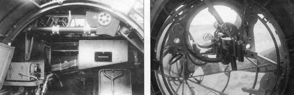
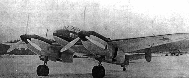
The Belyayev DB-LK [airwar.ru]In the late thirties and early forties, the Soviet aviation industry had developed and tested a variety of aircraft design concepts, some quite peculiar. While generally unknown around the world, a number of these strange aircraft would represent a serious departure from anything resembling their contemporaries. Such is the case with Victor Nikolayevich Belyayev’s DB-LK experimental long-range bomber.
History
Victor Nikolayevich Belyayev, March 1896 – July 1953, began working for the Department of the Marine Experimental Aircraft Construction, OMOS, in 1925, where he gained his first experience in aircraft design. In the following years, he worked for the Central Aerohydrodynamic Institute, TsAGl, and Tupolev. During this time, he became an advocate for tailless aircraft designs. He also argued that the so-called “batwing” or “butterfly”, offered better performance, due to their reduced drag and better stability, than regular wing designs.
The “batwing” design possessed a slightly forward-swept wing with back curved tips. Belyayev managed to construct a glider, designated BP-2, which was equipped with this kind of wing design in 1933, on which he tested this concept. During its test flight, it was successfully towed in the air from Crimea to Moscow, where it proved to have good stability and control during flight.
The BP-2 glider in flight. [airwar.ru]The next year, Belyayev participated in the competition for a new Soviet military transport plane design. His design was unusual, as it consisted of a large wing and two nacelles, powered by Tumanskii M-87B 950 hp (708 kW) engines. His design was not approved nor did he build a working prototype. However, four years later, he would reuse this project and adapt it for the role of a long-range bomber. In 1938, he designed the DB-LK long-range flying wing bomber, which the TsAGl approved and ordered the construction of a fully operational prototype. The prototype was built the following year by factory No.156 and by November 1939 it was ready for testing.
Technical Characteristics
The DB-LK had an unusual overall design with no classical fuselage. Instead, the crew, armament, and other equipment were located in the two extended engine nacelles that ended in glazed tail cones (gondolas), somewhat similar to the later German Fw 189. The two extended engine nacelles were, technically speaking, the plane’s fuselage. The semi-monocoque fuselages were constructed by using a combination of metal frames and longerons covered with a duralumin sheet. The DB-LK was designed in this unusual configuration in the hope of reducing the overall drag and weight and thus increasing its speed and range.
The DB-LK’s wings had a unique design, where beside the “batwings” there was an additional center wing section between the two fuselages. Also, the wings were slightly swept to the front with back curved tips. The wings consisted of an airframe covered with light metal stressed-skin. The outer wings had a Gottingen 387 profile, while the center section had a CAHI (TsAGI) MV-6bis profile. The wing edges were curved at an angle of -5° 42′.
A side view of the DB-LK. The strange wing design can be seen. [elpoderdelasgalaxias.wordpress.com]The rear tail was located on the middle section wing between the two fuselages. The tail consists of one fin and a large 20 ft2 (1.9 m2) rudder. Above the rudder, a smaller tailplane with two, one on each side, large elevators was placed.
A rear view where the large tail and the left glazed rear cone can be seen. [airwar.ru]One Tumansky M-87B 950 hp (708 kW) 14-cylinder radial engine was installed at the front of both nacelles. For these engines, three-bladed propellers with variable pitch were used. It was planned to upgrade these two with much stronger 1,100 hp (820 kW) M-88 engines, or even the 1.700 hp M-71, but this was never implemented. The fuel was stored in the wing and fuselage tanks, with a total fuel load of 3.444 l.
The landing gear retracted rearwards, with one wheel (900 x 300 mm) in each fuselage. During later testing, the landing gear design was changed with a forward retractable one. This whole landing gear system was operated hydraulically. There was a small fixed rear wheel (450 x 150 mm) located at the bottom of the tail unit.
The DB-LK was to be operated by a crew of four: the pilot, navigator, and the two rear gunners. The pilot position was in the left cockpit and the navigator in the right. The gunners were positioned in both rear glazed cones. One of the two gunners was also the radio operator. The crews entered their positions through roof hatch doors. The two glazed cones could be mechanically rotated 360° by using a small electric engine located at the fuselage top, but the sources do not specify why this was done.
Inside the pilot cockpit [авиару.рф]The interior of one of the two fuselages. In the picture on the right, the rear machine gun mount can be seen. On the left, the radio and the mechanism that rotated the whole glazed cone can be seen. [авиару.рф]Both rear glazed tail cones had a recess where a twin 7.62 mm (.30 caliber) ShKAS machine gun mount was installed. These machine guns had a -10 to +10 field of fire in all directions. Besides these four machine guns, there were two additional ones forward mounted in the leading edge of the center section. These two machine guns were operated by the pilot. In total, around 4,500 rounds of ammunition were provided for these machine guns. The bomb bays were located behind the landing gear doors in each of the two nacelles.
Depending on the sources, the load capacity of the bomb carried is different. The authors Yefim G. and Dimitri K. note that the bomb load was 1000 kg (2,200 lb) with another 1000 kg that could be carried on external racks. According to Bill G., the capacity of each bomb bay (in each fuselage) was one 1000 kg (2.200 lb), two 500 kg (1.100 lb), or smaller bombs with a total of 1000 kg (2.200 lb) weight.
Both front and rear views of the DB-LK’s unusual design. [авиару.рф]
Flight Tests
While being completed in November 1939, the first extensive flight test would only begin the following year. This was due to the unwillingness of the test pilot to fly this plane. He did not believe that it was safe to fly due to its unorthodox design. During this time, the plane received the nickname “Kурица” (chicken).
In order to move the entire project testing through this roadblock, the Soviet Direction of the Air Force Scientific test institute, GK Nil WS, appointed M. Nyuikhtikov as the main test pilot, supported by aircraft engineer and test pilot T. T. Samarin and N. I. Shaurov. Under the new leadership, the tests were carried out in the spring of 1940. During the new leadership, the DB-LK was extensively tested in over 100 flights.
During these flights, the pilots managed to reach speeds of 245 mph (395 km/h) at sea level and 300 mph (490 km/h) at an altitude of 16,400 ft (5,000 m). The DB-LK needed a 2,030 ft (620 m) long airfield for landing and taking off. However, the DB-LK was never truly trialed with a fully loaded payload. The numbers presented above would have likely been different with a full payload of equipment.
The test pilot Nyuikhtikov, after flying on the DB-LK, pointed out some issues with the plane’s design. The main problems were the inadequate overall flight-control system, poor visibility for the pilot and the navigator, especially on the ground. He also noted the poor construction of the landing gear. These reports were examined by the Nil WS Commission led by A. I. Filin. They agreed that the control system should be improved, but Filin had a positive opinion on the landing gear construction. Ironically, during a test flight, where Filin was the pilot, there was a landing gear malfunction during the landing when one of the front wheels broke free, after a possible collision with a treetop. The aircraft was only lightly damaged and the testing continued, but this led to a change in the landing gear design.
There were also other problems mentioned during the tests, like uncomfortable cockpits, low-level of fire protection, structural problems, a limited firing arc of the rear-mounted defense machineguns, and the tendency for the crew compartments to be filled with exhaust fumes from the engines. To solve these issues, there were plans for the DB-LK improvements, with stronger engines, wings, and various other modifications, to be completed by late 1940 but they were probably never implemented.
Rearview of the accident. [авиару.рф]
Conclusion
Despite plans for more testing and improvements, unfortunately for the DB-LK design team, they never got a chance to do so. In late 1940, the Nil WS Commission gave orders for the cancellation of the DB-LK program. The main reason for this was the decision for the production of the Il-4 as the main Soviet long-range bomber.
Nazi Germany (1943) Rocket Powered Fighter – 10 Built
The first operational Me 163 prototype. [luftwaffephotos.com]During the Second World War, the Luftwaffe experimented with a number of unorthodox designs. This included a handful of rocket-powered aircraft, like the Me 163. This particular aircraft was created thanks to the somewhat unexpected combination of two different projects. One was the airframe designed by Alexander Martin Lippisch, and the second was the rocket engine developed by Helmuth Walter. Following the testing of the first prototypes, a small series of some 10 aircraft were built that were mainly used for testing and training.
Alexander Martin Lippisch and Helmuth Walter
The history of Me 163 was closely related to the work and design of aircraft engineer Alexander Martin Lippisch and rocket development pioneer Helmuth Walter. Lippisch was somewhat unorthodox in his aircraft design work, to say the least. He was quite interested in the development of gliders and later aircraft that were either completely lacking a tail unit or of an all-wing configuration.
In 1921, Lippisch, together with a colleague, participated in the formation of the so-called Weltensegler GmbH (World Glider Ltd.) company. At that time, the Germans were prohibited from developing and building military aircraft. The Germans worked around this prohibition by instead focusing on gliders and civilian aircraft which if needed would be quickly converted for military use, and conducted secret experiments. While glider development may seem like a waste of effort, it actually provided the Germans with an excellent foundation on which they managed to develop the Luftwaffe during the 1930s, becoming a formidable force at the start of the war. In 1925, Lippisch joined Rhön Rossitten Gesellschaft RRG, where he soon began working on his first glider. It was named Storch I, and incorporated his unusual all-wing design.
Over the years, Lippisch also became interested in rocket technology. With assistance from Fritz von Opel, Lippisch managed to build a rocket-assisted glider. This contraption was flight tested in June 1928. This was actually the first-ever rocket-assisted flight in the world. While initially successful, the glider crash-landed, and caught fire. The plane would be lost in the accident.
This accident did not prevent Lippisch from experimenting with rocket-powered all-wing gliders. He focused his work on a powered version of his Storch V glider. For this project, he used an 8 hp DKW engine. His work was successful and he managed to find investors who were willing to provide funds for the project. This led to the development of the Delta I all-wing aircraft during the late 1920s, and it was followed by Delta II, III, and IV.
Lippisch Delta I prototype. [aviastar.org]Following this, Lippisch joined the Deutsche Forschungsinstitut DFS, where he worked as an engineer. There, he developed a series of new glider designs, like the DFS 40. In 1938, the work of Helmuth Walter came to his attention. Walter was a young scientist who was highly interested in rocket propulsion. He managed to gain military funding, which greatly helped in his work. In 1937, he even managed to gain attention from the Reichsluftfahrtministerium RLM (German Air Ministry). The RLM formed a Sondertriebwerke (Special Propulsion System Department) with the aim of experimenting with rocket engines in the aircraft industry. While this department was mainly focused on developing rocket engines for short take-off assistance, Walter desired a more prominent role in rocket propulsion. He intended to develop a rocket engine that could replace standard piston engines. Walter managed to develop such an engine, named Walter TP-1, which was fueled by the so-called ‘T-Stoff’ (hydrogen peroxide) and ‘Z-Stoff’ (water solution of either calcium or sodium permanganate). His engine design would be tested in 1939 on the He 176. However, the final results were disappointing and the engine did not go into production.
The DFS 194 predecessor
Lippisch and his design team began working on a new project incorporating the Walter rocket engine. Initially, the project was designated simply as Entwurf X (Design X), before being changed to 8-194 and finally DFS 194. Work on the prototype came to a temporary halt as the DFS lacked proper production capabilities to finish the aircraft. To keep the project going, the RLM instructed Messerschmitt to provide the necessary manpower and production support.
Given the small chance of progression in the DFS and in order to increase the speed of the project, Lippisch and his team moved to Messerschmitt’s base at Augsburg at the start of 1939. He also tried to negotiate with Heinkel for the production and development of the DFS 194 project, but nothing came of this. At Augsburg, Lippisch and his team worked in Messerschmitt’s newly formed Department L (which stands for Lippisch).
The DFS 194 prototype served as the base for the future Me 163. [nevingtonwarmuseum.com]The first calculations were promising, as the plane would be able to reach a speed of 550 km/h (342 mph). Once completed the DFS 194, was transported to the secret German rocket test center at Peenemunde-West Airfield during the summer of 1939. During ground tests, it was noted that the engine installation was poorly designed and too dangerous to be actually flight tested. Instead, it was decided to use the design as a glider. Surprisingly, despite this huge setback, production orders for three prototypes were given. Initially, these were designated simply as Lippisch V1, V2, and V3, but would be renamed to Me 163A V1 to V3. This was mainly done to mask the true purpose of this aircraft, as this was the name given to an older, rejected Bf 163 Messerschmitt reconnaissance aircraft project.
The Me 163A Prototype Series
The RLM was not satisfied with the general design of the engine compartment initially tested on the DFS 194. They requested that for further Me 163 development, it would need to be substantially changed. In addition, the engine was to be replaced with the Walter R II-203 engine. This engine was to have a manually regulated thrust ranging from 150-750 kg of thrust (330-1,650 lbs). The engine compartment was also to be completely redesigned in order to have easy access to the main components for maintenance.
Following the start of the Second World War in September 1939, the work on the Me 163 slowed down but still went on. The first unpowered flight by the Me 163 V1 prototype, in some sources marked as V4, (KE + SW) was carried out during early 1941. This prototype was towed by a Bf 110 heavy fighter. Once at a sufficient altitude, the V1 was released. During the test flight, the pilot, Heini Dittmar, managed to reach a speed of some 850 km/h (528 mph) during a dive. While this was a great starting point for the project, Hitler, following military victories in Poland and in the West, ordered that funds for such projects be reduced. In the case of the Me 163, this meant that only two more additional prototypes were to be built.
Side view of the Me 163 V1 (V4).[luftwaffephotos.com]In May 1941, a wooden mock-up of a Me 163 was completed, which was then transported to the Walter Werke. Once there, it was to be equipped with the R II-203 engine. Once the first prototype was fully completed and equipped with this engine, the first tests were carried out at Peenemunde-West in August 1941. The test pilot was once again Heini Dittmar. After a series of test flights that lasted from August to September 1941, the Me 163 prototype showed promising results. The pilot managed to reach top speeds of 800 km/h (500 mph). At this time, the second V2 prototype was also equipped with a rocket engine and used in various test flights. Ernst Udet, Director-General of the Luftwaffe, was highly impressed with its performance. He even gave orders that an additional 8 prototypes were to be built, bringing the total to 13 at this time.
Once the prototype was equipped with the R II-203 engine, the first tests were carried out in August 1941. These proved to be highly successful, which led to an increase in interest for the Me 163 project. [Spate & Bateson]At the start of October, Heini Dittmar said that, in order to fully test the Me 163’s flying performance, the fuel load had to be increased. On his personal insistence, the V3 (CD + IM) prototype, was fully fueled. This is according to W. Spate and R. P. Bateson (Messerschmitt Me 163 Komet). Other sources like M. Griehl (X-Planes German Luftwaffe Prototypes 1930-1945) this aircraft was described as being the V8 prototype instead. On the 2nd of October 1941, he took to the sky, initially towed by a Bf 110. At an altitude of 3,960 meters (13,000 ft), Dittmar activated the engine. After reaching a speed of 965 km/h (600 mph), he lost control of the aircraft as the result of compressibility effects. The prototype began a rapid descent toward the ground. He then switched off the engine, which enabled him to regain control, after which he landed safely on the ground. Later analysis of the flight indicated that Dittmar managed to reach a speed of 1002 km/h (623 mph). As the whole project was undertaken under great secrecy, this success was not published at the time.
The Me 163 in the middle was the aircraft that Heini Dittmar flew when he reached a speed of 1002 km/h (623 mph). [Spate & Bateson]Following these events, the Me 163 project got a temporary boost in prominence, with Herman Goring himself placing great interest in it. Ernst Udet additionally placed an order for 70 new Me 163 airframes together with engines for the B version in October 1941. A month later, things changed dramatically for Me 163 after Udet committed suicide. His replacement, Erhard Milch, was less interested in unconventional aircraft designs, like the Me 163. Work on the project nevertheless continued.
A breakup with Messerschmitt
While the Me 163 project was underway, relations soured between Willy Messerschmitt and Lippisch. Messerschmitt personally disliked the Me 163, partly due to its unique overall design, but also given that he was not involved in its development. By 1943, Lippisch left Augsburg and moved to Vienna. While not physically present in the design bureau, he tried to maintain contact with the Me 163 development team at a distance.
In the meantime, Messerschmitt was unwilling to be involved in the Me 163 project, under the excuse that his company was already overburdened with the production of other aircraft. For this reason, the production of further Me 163 aircraft was instead given to Klemm Leichtflugzeugbau, a relatively small aircraft company owned by Hans Klemm.
Production of the A-0 series
While the V1 prototype was mainly used for initial testing, the V2 would serve as a base for the A-0 series. An initial order for ten A-0 aircraft was previously given to Messerschmitt, but only seven were completed. The remaining three aircraft were actually completed by the Klemm factory. These were all completed from 1941 to 1942. The number of prototypes built is not clear in the sources. The numbers range from 1 to 8 prototype aircraft. According to S. Ransom and H.H. Cammann (Jagdgeschwader 400), while three prototypes were meant to be built initially, not all met the requested specifications, except one, which received the V4 designation. Author M. Griehl (Jet Planes of the Third Reich) on the other hand noted that the V4 was the first prototype. He explained that the previous three prototypes were actually related to the initial Bf 163 reconnaissance project that was rejected.
In-Service
Of the 10 built Me 163 A-0 planes, not all were equipped with fully operational engines. A number of them were instead operated as unpowered gliders. This version was not intended for combat operations and was mainly used for crew training and further experimentation.
At the end of November 1943, the V6 aircraft was lost in an accident with the loss of the pilot. In another accident at the end of 1943, another pilot died when the engine stopped working during a takeoff. While the pilot tried to turn back for a landing, having limited control, the aircraft hit a ground station radio antenna before hitting the ground and exploding. It was discovered in an investigation that the undercarriage dolly bounced off the ground much higher than usual, and struck the aircraft, damaging the rocket engine. Some prominent pilots, like Hanna Reitsch, actually had the chance to flight-test the Me 163 aircraft. At least one aircraft was still operational by February 1945 and was used for testing the 55 mm R4M rockets by Erprobungkommando 16.
Me 163A at Peenemunde, 1943. [Ransom & Cammann]At least one Me 163A survived up to February 1945. It was used by Erprobungkommando 16 (Eng. testing or evaluation-coomand) in Silesia to test the 55 mm R4M rockets. This unit had the primary function of testing and examining the newly built Me 163 and helping in the development and improvement of its overall design. Besides these, no other armament was installed on the Me 163 A series. Source Source: W. Spate and R. P. Bateson Messerschmitt Me 163 Komet
Technical Characteristics
The Me 163A was a high-speed, rocket-powered, swept-wing, short fuselage, mixed-construction tailless aircraft. The Me 163A fuselage was built using metal, divided into three sections, the front cockpit, central fuel tank, and the aft engine compartment.
The wooden wings had a very simple design consisting of two spars covered in thick fabric. If needed, the wings could be detached from the fuselage for transport. At the wings’ trailing edges ailerons were placed, which the pilot during flight used for pitch and roll. The wing area was 17.5 m² (57.4 ft²). The tail did not have the standard horizontal stabilizers, instead of having a single large vertical stabilizer. Despite this, no major problems during flights were ever noted on the Me 163A.
For the pilot to enter the cockpit he was provided with a ladder placed on the left side of the aircraft. The cockpit canopy opened upwards. Overall visibility was poor, and later versions would have an improved canopy. While it did offer some improvements for the pilot’s line of sight, it would not resolve the overall poor visibility of the aircraft. Given that the Me 163A was based on a DFS 194 glider, it was equipped with minimal instrumentation needed for the aircraft to be flown.
View of the Me 163A’s cockpit interior. [Spate & Bateson]The Me 163A was powered by a single HWK R II 203 rocket engine, which gave 750 kg (1,650 lb) of thrust. The main fuel consisted of a mix of T and Z Stoff. These two chemicals were highly reactive, volatile, and prone to explosion. To avoid this, extensive preparation and security measures were necessary. The maximum speed this engine achieved was some 850 km/h (530 mph). This high speed was achieved to some extent thanks to the aircraft’s low weight. The empty weight was 1,140 kg (2,513 lbs) while the maximum takeoff weight was 2,200 kg (4,850 lbs).
Interestingly, in order to save weight, the Me 163 did not have a conventional landing gear unit. Instead, during take-off, it was provided with a specially designed two-wheel dolly. It would be jettisoned upon take-off. When landing on the airfield, the Me 163 used a retractable skid located beneath the fuselage.
Despite the A series having not been designed to have any weapon systems, at least one Me 163A was tested with the installation of the 5.5 cm (2.16 in) R4M air-to-air rockets.
Production Versions
DSF 194 – Prototype whose further development led to the creation of the Me 163
Me 163 Prototype Series– Prototype aircraft
Me 163A-0 – 10 Pre-production aircraft built
Conclusion
The Me 163A series, despite its unusual appearance and overall design, proved to be a rather successful aircraft. It had some shortcomings, mostly regarding its dangerous fuel load. Upon completion of successful testing, order for the Me 163B version was given.
Me 163A Specifications
Wingspans
8.85 m / 29 ft 3 in
Length
5.25 m / 17 ft 2 in
Height
2.16 m / 7 ft 8 in
Wing Area
17.5 m² / 57.4 ft²
Engine
One HWK R II 203 rocket engine with 750 kg (1,650 lbs) of thrust
Empty Weight
1,140 kg / 2,513 lbs
Maximum Takeoff Weight
2,200 kg / 4,850 lbs
Maximum Speed
850 km/h / 530 mph
Crew
1 pilot
Gallery
Me 163A – Illustrated by Carpaticus
Credits
Written by Marko P.
Edited by by Ed Jackson & Henry H.
Illustrations by Carpaticus
Sources
D. Nešić (2008) Naoružanje Drugog Svetsko Rata-Nemcaka. Beograd.
W. Spate and R. P. Bateson (1971) Messerschmitt Me 163 Komet , Profile Publications
M. Ziegler (1990) Messerschmitt Me 163 Komet, Schiffer Publishing
M. Emmerling and J. Dressel (1992) Messerschmitt Me 163 “Komet” Vol.II, Schiffer Military History
E. T. Maloney and U. Feist (1968) Messerschmitt Me 163, Fallbrook
S. Ransom and H.H. Cammann (2010) Jagdgeschwader 400, Osprey publishing.
D. Donald (1990) German aircraft of the WWII, Brown Packaging books ltd
D. Monday (2006) The Hamlyn Concise Guide To Axis Aircraft OF World War II, Bounty Books.
M. Griehl (1998) Jet Planes of the Third Reich, Monogram Aviation Publication
M. Griehl (2012) X-Planes German Luftwaffe Prototypes 1930-1945, Frontline Book
He 112 the unsuccessful competitor of the Bf 109. [luftwaffephotos.com]Prior to the Second World War, the German Luftwaffe was in need of a new and modern fighter that was to replace the older biplane fighters that were in service. While four companies responded to this request, only the designs from Heinkel and Messerschmitt were deemed sufficient. The Heinkel He 112 was an especially good design that offered generally acceptable flight characteristics and possessed a good basis for further improvements. While it was in some regards superior to the Messerschmitt, ultimately it would not be accepted for service, and only 100 or so aircraft would be built. These would be mainly sold abroad, with those remaining in Germany used for various testing and evaluation purposes.
History
By the early 1930s the Heinkel company was a well-established aircraft manufacturer. It was rapidly expanding, mostly thanks to the export of some of its aircraft designs. The Heinkel company also had a good relationship with the German Air Ministry RLM (Reichsluftfahrtministerium RLM), which entered a series of different aircraft production contracts with Heinkel.
At this time the German Air Force was in the process of a huge reorganization, and the development of new military aircraft. Quite of interest was the development of a new fighter aircraft that would replace older Arado Ar 68 and Heinkel He 51 biplanes that were in service. For this reason, in May 1934 the RLM issued a competition for a new and modern fighter plane that could reach speeds of 400 km/h (250 mph) at an altitude of 4,000 meters (19,685 feet). Initially, three companies were contacted, including Arado, Focke-Wulf, and Heinkel. Interestingly, and somewhat ironically as it later turned out, Messerschmitt, a relatively small company at that time, was also contacted by the RLM.. All four companies were to build three prototypes of their design, which were to be tested before a final decision was to be made.
Arado and Focke-Wulf completed their prototypes, the Ar 80 and Fw 159 respectively, by the end of 1934. The Heinkel He 112 and Messerschmitt Bf 109 prototypes took a bit longer to complete, which was completed in September 1935. The He 112’s design was greatly inspired by the He 70 passenger plane, which would later be modified for military purposes. Heinkel engineers used the He 70’s the overall design as the basis for the He 112, mainly regarding its wings and the fuselage construction.
The inspiration for the He 112 was the He 70. While the He 70 had good general performance it would not be employed by the German in any major military role. [Wik]Once all four companies submitted their designs, evaluation trials were carried out at the German test centers located at Rechlin and Travemunde starting in October of 1935. After some initial testing, both the Ar 80 and Fw 159 experienced too many mechanical breakdowns and even crashes, which ultimately led to both being rejected. The He 112 and Bf 109 on the other hand proved to be more promising designs. Interestingly due to shortages of domestically built engines, both aircraft were initially powered by Rolls-Royce Kestrel engines.
The He 112 V1 (D-IADO) was powered by a 695 hp Rolls-Royce Kestrel Mk. II engine during trials. Once the aircraft was completed, it was first flight-tested by Heinkel’s own test pilot Gerhard Nitschke. While he gave a generally positive review of its performance, he also noted the aircraft’s drag was a bit higher than expected. However, given that its overall performance was deemed sufficient for the competition, Heinkel decided to proceed with the project. This prototype arrived at the designated test center of Travemunde by the end of 1935. During a series of flight tests, the maximum speed achieved was 466 km/h (290 mph).
The He 112 V1 first prototype, used for the trials held at Rechlin and Travemunde. [luftwaffephotos.com]It was clear that the RLM would never accept an aircraft powered by a foreign engine. The Heinkel engineers began working on the second prototype that was to be equipped with a domestically built engine. The V2 (D-IHGE) was powered by a 640 hp Junkers Jumo 210C liquid cooled engine. The first test flight was made in November 1935 by another Heinkel test pilot Kurt Heinrich. The V2 was more or less just a copy of the first prototype.
Construction of Additional Prototypes
During the series of test flights, the performance of the two competitors was quite similar, with some minor advantages between them. In the case of the Bf 109, it was slightly faster, while the He 112 had lower wing loading. In addition, the He 112 had a better design and safer landing gear unit.
As the V2 was flight tested at Heinkel, the initial results of the competition began to arrive. The Heinkel engineers were keen on finding a way to overcome the Bf 109’s slightly faster speed. So the Gunter brothers began to redesign the V2 wings. Walter and Siegfried were at that time, probably Heinkel aircraft designers (for example the He 51 biplane is one of their designs.). Their calculation showed that a reduction in the wing profile would provide an additional boost to the maximum speed by at least 24 to 29 km/h (15 to 18 mph). This modification reduced the overall size of the wings, but led to another problem. Namely, the wing loading exceeded that of the RLM commission requirement. Given that the aircraft speed was increased, Heinkel officials deemed that it was a necessary compromise that would not affect the general rating of the aircraft.
The V2 prototype reached the Travemunde test center sometime in early 1936. In February 1936 the V1 and V2 prototypes were moved to the Rechlin Testing Center. In early March, a series of dive tests were carried out. In one of these, the V2 was seriously damaged, luckily the pilot survived the crash. After a few weeks of repairs with Heinkel, the aircraft was quickly put back to use. But in another landing crash, it was completely destroyed and listed as irreparable. Once again the test pilot managed to escape without any injury. This accident, while it did not prevent Heinkel’s involvement in the new fighter competition, it certainly affected the commission’s opinion on the He 112 at least to some extent.
The last of the prototypes intended for the competition was the V3 (D-IDMO). While initially, it was more similar to the first prototype, it received the wing modification implemented on the V2. Additional changes include increasing the rear tail unit size, adding a new radiator, installation of three (or two depending on the source) 7.92 mm MG 17 machine guns. In addition, it would later receive a new enclosed cockpit with a sliding canopy.
Side view of the V3 (D-IDMO) prototype. [luftwaffephotos.com]
Further Competition Developments
Despite the series of improvements to their He 112 design, the tide was slowly but surely turning toward the Bf 109. The RLM commission was getting somewhat frustrated with Heinkel’s constant changes to the design, and the previously mentioned crash did not help matters. In March, it was already being discussed to proclaim the Bf 109 as a winner. The Germans were also informed by the Abwehr intelligence service that the British were developing and preparing for the production of the new Spitfire. RLM officials were simply not willing to risk taking a chance on an aircraft design that could not quickly be put into production, as the Bf 109 was.
While the He 112 project would have ended there, thanks to Heinkel’s strong political connections, an extension of the trials was agreed to. Both companies were to build additional 15 0-series aircraft to be used for testing. The production was to commence in October 1936 with the last aircraft to be completed by May the following year.
Heinkel’s first completed aircraft, which was included in the previously mentioned contract, was actually a He 112 V4 (D-IDMY) prototype which was ready in June 1936. The V4 received a new and stronger 680 hp Jumo 210D that was equipped with a supercharger. In addition, it had an open cockpit, besides which it was in essence a copy of the V3. Possibly anticipating the contract for additional aircraft, Heinkel began working on additional airframes in advance. This led to the completion of the V5 (D-IIZO) and V6 (D-IQZE) prototypes in July of 1936. The V6 was intended as a replacement for the lost V2 aircraft. This aircraft was powered by a Jumo 210C engine. The last aircraft of the prototype series was the V8 (D-IRXO) powered by a Daimler DB 600A engine. It was primarily intended to serve as test aircraft. All of these previously mentioned prototypes were to serve as the forerunners of the He 112 A-0 series.
The V4 prototype before it received any markings. [luftwaffephotos.com]Following more test flights by numerous Luftwaffe pilots, the Bf 109 was receiving more and more positive reviews from pilots that had the opportunity to fly them. The Bf 109, while proving to have excellent flying performance, was also cheaper and easier to build than the He 112. Given the fact that the Germans were attempting to accelerate the production of the new fighter, this was seen as a huge advantage over the He 112.
In late 1937 Ernst Udet, who was at that time the director of the RLM technical development sector, visited the Heinkel company Marienehe Test Site. There he informed Heinkel that his He 112 was rejected as a fighter. Possibly to compensate for the huge investment in the fighter project, Heinkel company was permitted to export the He 112.
Heavy Fighter Role
Parallel with the development of the first fighter aircraft, the RLM was also interested in the so-called Zerstorer (heavy fighter). This aircraft was to be armed with cannons and machine guns. Heinkel proposed that the V6 be armed with a 2 cm MG C/30L cannon placed in the centerline of the engine. According to D. Bernard the V6 was designated for further testing, under real combat conditions, and would be sent to Spain at the end of 1936. It would be lost there in a landing accident in July 1937. Ernst Heinkel was likely dissatisfied with this outcome, as Messerschmitt once again triumphed as its Bf 110 would be accepted for this role.
The A and B series
Despite being inferior to the Bf 109, the Heinkel company continued working on the He 112, improving its design, in the hopes of gaining the attention of the RLM. The construction of the limited production He 112 A-0 series was still underway, with a total of only six aircraft (D-ISJY, D-IXHU, D-IZMY, and D-IXEU) built. The last two aircraft of the A-0 series received no registration numbers, as they were intended to be sold to Japan. The remaining four aircraft were used for various proposals. For example, the A-01 aircraft was to be used as a base for the proposed He 112 C-0 aircraft carrier modification, which was never implemented. The A-02 and A-04 were used for further flight tests. The A-03 was mainly used as an exhibit aircraft for various European aviation exhibitions, which were quite common before the war.
The A-series was built in small numbers and mostly employed for testing various equipment and design changes. [luftwaffephotos.com]The A-series was built in small numbers, as Heinkel’s attention moved to the B-0 series instead. The B-0 series was quite different from the previous version, as it introduced a number of changes and modifications. Some of which included a new cockpit design, more powerful armament, changes to the engine ventilation design, fuselage and engine cowling changes, and other modifications.. The forerunner of the B series was the He 112 V7 prototype, which included many modifications previously mentioned.
Following the unsuccessful attempt to gain the Luftwaffe’s attention Heinkel and his team of engineers began working on redesigning the He 112. The basis for the next version, the He 112B-0, the V7 (D-IKIK) was reused. It incorporated a newly redesigned wings and tail unit, and was to be powered by a 1,000 hp Daimler DB 600A engine. Heinkel officials and Hertel himself were hoping that this new version could potentially persuade RLM to reconsider the He 112. Following it was the V9 (D-IGSI), which was powered by a weaker 680 hp Jumo 210E engine. In the following months, work on the B-series was intensified with many different engines being tested (Jumo 210E, 210G etc). Ultimately meager export sales, and the RLM’s rejection of the He 112 by the start of 1939 forced Heinkel to finally terminate the project.
The B-series was in many aspects a complete redesign from the previous series. Including the introduction of a new tail unit, and part of the fuselage, to name a few [luftwaffephotos.com]
Rocket Engine Tests
Prior to the Second World War, the Germans were quite interested in the experimentation and the development of rocket technology. Various tests conducted by Dr. Wernher von Braun were carried out at the Kummersdorf-West test centers. While this research eventually led to the creation of the infamous V-2 rocket, the development of rocket engines that were intended to possibly be installed in aircraft is often overlooked. Ernst Heinkel was quite a supporter of this project and even donated a number of aircraft to be used as testbeds for the potential new engine. He even donated a few pre-production series He 112 for this research.
A rocket engine was installed in the rear of the fuselage, with the engine nozzle being placed just beneath the tail unit. During the first ground test, the engine exploded, destroying the aircraft (He 112 A-01) in the process. Another He 112 V3 aircraft was outfitted with the rocket engine and was being prepared to conduct its first test flight. As the pilot was approaching this aircraft, the rocket engine exploded again. Somewhat miraculously the pilot survived with no major injuries. While again the aircraft was lost, another aircraft that was built as a replacement would receive the same markings.
The V3 prior to the start of testing. Which would spectacularly explode shortly after the picture was taken. [luft46.com]Von Braun requested another aircraft which Henkel provided, this was the He 112 V8. During these trials it received a slightly altered designation V8/U. The plane was to ascend on its own piston engine. Then at a certain height, it was to fire the rocket engine wich was placed to the rear of the fuselage for a 30-second burst. This flight test was carried out in April 1937 and was more than successful. During the short burst, the plane reached a speed of 460 km/h (286 mph). The He 112 V8 was returned to Heinkel but two more aircraft (H7/U and A-03) would be donated for the rocket research program. The V8 would be eventually sent to Spain in 1937 and its final fate is unknown. Thanks to the He 112, the German rocket engine program gained a huge boost, which would eventually lead to the He 176 and later Me 163.
Technical Characteristics
The He 112 was an all-metal single-engine fighter. The monocoque fuselage consisted of a metal base covered by riveted stress metal sheets. The wing was slightly gulled, with the wingtips bending upward, had the same construction as the fuselage with a combination of the metal construction covered in stressed metal sheets.
During its development life, a great number of different types of engines were tested on the He 112. For the main production version, He 112 B-2, the 700 hp Jumo 210G liquid-cooled engine was used. With this engine the maximum speed achieved was 510 km/h (317 mph). For the Jumo engine, an all-metal three blade variable pitch propeller was used. The He 112 had a fuel capacity of 101 liters in two wing mounted tanks, with a third 115 liter tank placed under the pilot seat
The landing gear were more or less standard in design. They consisted of two larger landing wheels that retracted into the wings, and one smaller wheel placed at the rear. The He 112 landing gear was wide enough to provide good ground handling and stability during take-off or landing.
The pilot cockpit received a number of modifications. Initially, it was open with a simple windshield placed in front of the pilot. Later models had a sliding canopy that was either partially or fully glazed.
While the armament was changed during the He 112’s production, the last series was equipped with two 7.92 mm MG 17 machine guns and two 2 cm Oerlikon MG FF cannons. The ammunition load for each machine gun was 500, with 60 rounds each for the cannons. If needed, two bomb racks could be placed under the wings, with one per side. Each could carry one 10 kg anti-personnel bomb. For the acquisition of targets, the pilot used the Revi 3b gun sight.
Brief Service with the Luftwaffe
Despite losing to the Bf 109, Heinkel was permitted, after some lobbying from Ernst Heinkel himself, to send one He 112 to Spain for combat evaluation. Once it reached Spain during the end of 1936, the He 112 was allocated to the Experimental Fighter Unit 88 which was part of the Condor Legion. In Spain, it was mostly used against ground targets. One of its greatest successes happened during an attack on the Republican-held Cesena train station. The pilot, Obereutnant Balthasar, made three attack runs in which he managed to destroy an armored car and a tank. The aircraft would be lost in a landing accident that happened in July 1937. Two more prototypes would be sent to Spain during 1938, the V8 and V9. The V8 was heavily damaged during initial trials and spent some four months in repairs. The V9 had a better service life, as it was used in a number of ground attacks. Both aircraft would be returned to Germany by the end of 1938.
Only a small number of He 112 (less than 20) saw limited service with the Luftwaffe in 1938 [luftwaffephotos.com]In 1938 a possible conflict with Czechoslovakia and the Western Allies, France, and the United Kingdom over the dispute caused huge concern in the RLM. The Luftwaffe was simply not ready for open war, as it was not yet fully equipped. For this Reason, the RLM instructed that all available aircraft be relocated to the Luftwaffe to temporarily boost their readiness numbers. An unknown number of He 112 B, taken from the Japanese purchase order, were temporarily pressed into service. These were allocated to the IV./JG 132 station at Oschatz. In November they relocated to Mahrish-Trubau. Once the crisis was over, the aircraft were replaced with the Bf 109. The pilots that had the chance to fly them gave a generally positive review of their flying performance.
Export Attempts
As mentioned earlier, the He 112 was permitted to be exported abroad if there were any interested customers. This order was officially given at the end of January 1938. A number of countries such as Austria, Japan, Romania, and Finland showed interest, but only a few actually managed to procure aircraft.
Negotiation with Austria
During November 1937 an Austrian delegation visited Heinkel with a desire to enter into a purchase agreement for acquiring 42 He 112B aircraft. Due to lack of funds, this order was reduced to 36 at the start of 1938. Eventually, nothing came of this as the Germans simply took over Austria in March 1938.
In Japanese Hands
At the end of 1937, a Japanese delegation made a contract with Heinkel for purchasing 30 He 112B’s. If these proved to be satisfactory, an additional order for 100 would be placed. This order included 2 He 112 A-0, 6 B-0, and 21 B-1 and the V11 prototype. After a series of tests, the Japanese were not impressed with the He 112 and did not accept it for service. The experimental He 112 C aircraft carrier version was also sold to Japan, according to D. Bernard.
J. R. Smith and A. L. Kay provide a completely different story. According to them, Japan expressed an interest in buying 30 He 112B-0 aircraft, with the first group of 12 aircraft arriving in Japan in 1938. While the remaining 18 were to arrive soon after, the Sudeten crisis changed the plan. The Germans were preparing for a potential war with Czechoslovakia and needed every possible aircraft. So they requisitioned the aircraft intended for Japan. Once the crisis was over, Heinkel offered to ship these delayed aircraft to Japan, which rejected the offer. The Japanese were disappointed with the He 112 B-0 performance and decided to cancel the purchase. The sources also conflicted with each other if the He 112 in Japanese service ever saw action.
In Spain
Some three He 112 were tested during the Spanish civil war. Thanks to this, Francisco Franco’s forces had some insight into the He 112’s performance. Based on this, Spain initially asked for 12 aircraft. The order would be eventually increased to 18 aircraft. Interestingly, Spanish pilots managed to shoot down an Allied P-38 that likely accidentally entered the Spanish air space while flying the He-112B-0 in 1943.
He 112 in Spain’s service. [luftwaffephotos.com]
In Romania
Romania initially asked for 24 aircraft, with the order later increased to 30 He 112 aircraft. These arrived from June to October (or September) 1939. The Romanian He 112 would be used during 1941 against the Soviet Union. The following year, all would be allocated for pilot training.
Romanian He 112 even saw service against the Soviet Forces during 1941. [luftwaffephotos.com]
Hungary
The last nation that operated the He 112 was Hungary. In September 1937 a delegation from Hungary visited Heinkel where they inspected the He 112. This delegation was satisfied with what they saw and ordered 36 aircraft, but also showed interest in a licensed production. Ultimately the RLM rejected this offer and only one aircraft ever reached Hungary.
Other Unsuccessful Negotiations
Prior to the war, Heinkel organized a series of demonstrations of the He 112B to various interested European air forces. These include Yugoslavia, The Netherlands, Finland, Turkey, and Switzerland. While many of these parties were interested, for various reasons, chiefly budget constraints, nothing came of these negotiations.
Production
The production numbers of the He 112 are not clear and vary widely depending on the source. According to F.A.Vajda and P. Dancey the production run was as follows with 3 in 1935, 11 in 1936, 13 in 1937, 30 in 1938, and 46 in 1939 for a total of 103 aircraft. Author D. Berliner mentioned a number of 66 aircraft being built. Author Duško N. gave a number of 68 aircraft of all versions being built. D. Bernard gave us a number of 98 aircraft. While C. Chants mentioned a number of 110 aircraft.
Prototype and Production Versions
He 112 V1-V – Prototype series used for testing of various engines and overall design
He 112 A – Planed main production version, which was not adopted
He 112 B – Extensively modified versions of preceding models
He 112 B-1 – Equipped with a Jumo 210E engine
He 112 B-2 – Equipped with a Jumo 210G engine
He 112 B-3 – Proposed version powered by a Daimler DB 601A engine, none built
He 112 C – A proposed aircraft carrier version, only one prototype was built and sold to Japan
He 112 E – Intended as an export version, based on the B series
He 112 U – Propaganda aircraft, which was actually based on the He 100
Operators
Germany – Briefly operated a small number of the He 112
Japan – Operated some 12 to 30 aircraft mainly for testing
Spain – Operated less than 20 He 112 aircraft
Romania – Purchased some 24 to 30 He 112, which saw combat action against the Soviet Union
Hungary – Purchased one He 112
Austria – Planned to acquire 42 He 112, but nothing came from this as it was annexed by Germany.
Conclusion
The He 112 during its brief service life was shown to be a good fighter aircraft. It proved to be a worthy competitor to the Bf 109. It’s quite difficult to pinpoint the exact circumstances that ultimately led to its downfall. Sources often mention that one of the main reasons was political involvement, which favored Messerschmitt. Political quarrels in Germany often influenced decision to adopt aircraft during the war. This factor was surely at play when the fate of the He 112 was decided. But a more practical answer was simply that the Bf 109, while shown to have good flying performance, was also cheaper and easier to build than the He 112. Given that at that time, the Luftwaffe was in the middle of a huge reorganization and rearmament effort, conditions certainly favored the Bf 109. The He 112’s constant design changes did not help either.
He 112B-2 Specifications
Wingspans
29 ft 10 in / 9.1 m
Length
30 ft 2 in / 9.22 m
Height
12 ft 7 in / 3.82 m
Wing Area
180 ft² / 17 m²
Engine
One 700 hp Jumo 210G liquid-cooled engine
Empty Weight
3,570 lbs / 1,620 kg
Maximum Takeoff Weight
4,960 lbs / 2,250 kg
Climb Rate to 6 km
In 10 minutes
Maximum Speed
317 mph / 510 km/h
Cruising speed
300 mph / 484 km/h
Range
715 miles / 1,150 km
Maximum Service Ceiling
31,170 ft / 9,500 m
Crew
1 pilot
Armament
Two 20 mm cannons and two machine guns 7.92 mm machine guns
Illustrations by Godzilla
He 112 as seen during its brief service with the LuftwaffeAn alternate livery of the Luftwaffe He 112He 112 in Romanian ServiceHe 112 in Romanian ServiceHe 112 v5 as it was tested by Japan
Credits
Written by Marko P.
Edited by by Ed Jackson & Henry H.
Illustrations by Godzilla
Sources
Duško N. (2008) Naoružanje Drugog Svetsko Rata-Nemаčaka. Beograd.
D. Monday (2006) The Hamlyn Concise Guide To Axis Aircraft OF World War II, Bounty Books.
D. Berliner (2011) Surviving fighter aircraft of World War two, Pen and sword
F.A.Vajda and P. Dancey (1998) German aircraft industry and production 1933-1945, Airlife Publishing Ltd.
J. R. Smith and A. L. Kay (1990) German Aircraft of the Second World War, Putnam
D. Bernard (1996) Heinkel He 112 in Action, Signal Publication
R.S. Hirsch, U, Feist and H. J. Nowarra (1967) Heinkel 100, 112, Aero Publisher
C. Chants (2007) Aircraft of World War II, Grange Books.
Poland (1939) Transport and Ambulance Aircraft – 7 Built
The Lublin R-XVI. Source: Wiki
Following a request for a new passenger transport aircraft, the Plage and T. Laśkiewicz aircraft manufacturer developed the Lublin R-XVI. While it was not accepted for production, it would be built in a small series as a successful ambulance aircraft and used up to the Second World War by the Poles.
History
During early 1929, the Polish P.L.L airline, with the assistance of the Ministry of Transport, opened a contest for a new four-passenger transport plane. This aircraft was to be powered by a 220 hp Wright/Škoda radial engine. This contest was heavily influenced by the Polish Department of Aeronautics, which favored domestic manufactures. Aircraft manufacturer Plage and T. Laśkiewicz from Lublin (hence, all their products were named after that city) responded with the R-XI. Ultimately, this contest ended in failure, as none of the proposed aircraft proved satisfactory.
New specifications for a second contest were issued by the end of 1930. This time, Plage and T. Laśkiewicz presented a new model, the Lublin R-XVI design by Jerzy Rudlicki. While being based on the previous R-XI, there were a number of changes, like separating the cockpit from the crew compartment and changing the wing design. The novelty this aircraft introduced was the use of chrome-molybdenum tubes for the structure, a first in Poland, which reduced the weight.
When the prototype was completed, it was flight tested by Wladyslaw Szulczewski in February 1932. In the following months, the R-XVI was tested with different payloads. During these flights, the maximum speed achieved was around 194 km/h (120 mph). During 1932, the R-XVI was used mostly for postal service by the P.L.L. While the R-XVI proved to be satisfactory, its competitor, P.W.S., was chosen instead as the winner of this competition.
A New Role
Although they lost the competition, Plage and T. Laśkiewicz were instead contacted by the Medical Aviation Research Centre in cooperation with the Polish Red Cross. They were interested in the R-XVI plane and asked for certain modifications. These included adding space for two stretchers and a doctor, along with storage for additional medical equipment. This implementation was approved by the Ministry of Transport and the prototype was to be modified for this role. The aircraft was then renamed to R-XVIB, with the SP-AKP registration. Beside the changes to the interior passenger compartment, the fuselage was strengthened. These modifications were completed by the spring of 1933, when the aircraft was flight tested again.
Front view of the converted R-XVIB prototype aircraft. Source: Wiki
At the International Congress of Military Medicine in Madrid
This aircraft was presented to the VIIth International Congress of Military Medicine and the IInd International Congress of Medical Aviation, which was held in Madrid in 1933. Its crew consisted of the pilot, Zygmunt Janicki, mechanic Leon Zamiara and doctor Maj Kazimierz Michalik. The R-XVIB had the honor of being the first medical aircraft in the history of these Congresses to actually directly arrive by air. It also proved to be the best medical aircraft design present. The R-XVIB even won the first prize, the Raphael Cup, by beating the Spanish Trimotor and French Potez 29. When the Polish crews returned, they managed to fly the distance of 5,730 km (3,560 miles) without any problems.
Production Orders
Following the R-XVIB’s success in Spain, Plage and T. Laśkiewicz received production orders for one more prototype and five operational planes. The new prototype was completed during 1934. It was slightly different in comparison to the first aircraft. The most obvious change was the redesigned fuselage, improving the pilot’s visibility and using new types of landing wheels fitted with brakes and shock-absorbers. All aircraft were completed and put into service by the end of 1934.
Technical Specifications
The R-XVI was designed as a high-wing, single-engine, mixed construction transport/ambulance aircraft. The fuselage was built using chrome-molybdenum metal tubes and then covered with fabric. The one-piece wings were built using two spars which were covered by plywood. The wings were connected to the upper part of the fuselage by four bolts. The tail construction was the same as the fuselage, with a combination of steel tubes and fabric.
The R-XVI was powered by a 220 hp Škoda J-5, a nine-cylinder air-cooled radial engine, built under license after the J-5Wright Whirlwind engine. It was fitted with a two-blade fixed wooden propeller. The fuel load was stored in an aluminum tank (257 liters) which was placed in the upper part of the fuselage between the the wings.
The R-XVI high wing design and the fixed landing gear are evident in this photograph.. Source: Airwar.ru
The cockpit was placed at the front of the fuselage. To enter this position, the pilot was provided with a door. The crew compartment had room for four seats and one additional optional seat for a mechanic, if needed during the flight. There was a huge door for the passengers on the starboard side, with an additional smaller door for the luggage compartment on the port side. In the case of the later ambulance version, the crew compartment was redesigned to include two stretchers, placed one above the other. It was also equipped with shock-absorbing mounts for a more convenient flight for the patients. To bring the patients inside the plane, a large door was placed on the starboard side. On the opposite side, there was a door for the medical attendant. The interior of the medical version was provided with a first aid kit, washstand with running water, and lights.
The R-XVIB, which was designed as an ambulance aircraft, had specially designed folding doors to bring the patients inside the plane. Source Airwar.ru
The fixed landing gear consisted of two wheels. These were provided with vertical shock absorbers and brakes. If needed, there was an option to replace the landing wheels with skis. The original prototype had a small tail wheel, which was replaced on the later production model with a tail skid.
In Service
While not a combat aircraft, all R-XVIs were still operational by the time of the German invasion (1st September 1939) of Poland. By the time of the war, they were primarily used for wounded evacuation. While their final fate is unknown, they probably fell victim to the German air force.
Production and Modifications
The R-XVI was built in limited numbers for the Polish Red Cross. Besides the two prototypes, 5 additional aircraft were built.
R-XVI – Original proposed passenger aircraft prototype, later served as the base for ambulance version.
R-XVIB – Modified ambulance version, 6 aircraft were built (including a prototype).
Conclusion
While not accepted in its original role, the R-XVI would still see service as a medical aircraft used by the Polish Red Cross. In this role, they proved to be satisfactory and a small series of 5 aircraft was built. Their final fate sadly is not known and none survived the war.
Lublin R-XVIB Specifications
Wingspans
49 ft / 14.9 m
Length
33 ft 1 in / 10 m
Height
8 ft 7 in / 2.96 m
Wing Area
328 ft² / 30.5 m²
Engine
One 220 hp Wright Whirlwind (Škoda) J-5 nine-cylinder radial engine
Empty Weight
2,535 lbs / 1,150 kg
Maximum Takeoff Weight
3,590 lbs / 1,630 kg
Fuel Capacity
257 liters
Climb Rate to 1 km
In 6 minutes 30 seconds
Maximum Speed
118 mph / 190 km/h
Cruising speed
104 mph / 168 km/h
Range
479 miles / 800 km
Maximum Service Ceiling
14,635 ft / 4,600 m
Crew
Pilot and Medical Crew
Armament
None
Gallery
Illustrations by Carpaticus
Credits
Written by Marko P.
Edited by by Stan L. & Henry H.
Illustrations by Carpaticus
Sources
C. Chant. (2007) Pocket Guide aircraft of the WWII – 300 of the world’s greatest aircrafts, Grange books.
J. B. Cynk (1971) Polish Aircraft 1893-1939, Putham and Company
B. Belcarz and R. Peezkowski (2001) White Eagles: The Aircraft, Men and Operations of the Polish Air Force 1918-1939, Hikoki Publications
J. Koniarek Polish Air Force 1939-1945, Signal Publication.
Empire of Japan (1945) Kamikaze Aircraft – 105 Built
The Ki-115 suicide aircraft [Combat Workshop via Pinterest]
Throughout 1945, it was becoming clear to Japanese Army Officials that an Allied invasion of the Japanese mainland was growing ever more likely. Seeing as their navy and airforce had been mostly destroyed, they needed new weapons to fight off a probable Allied attack on Japan. Among these new weapons were Kamikaze aircraft, with many older designs having already been used in this role. However, some Kamikaze aircraft were to be specially designed for such a role, being cheap and able to be built quickly and in great numbers. One such aircraft was the Ki-115 Tsurugi (Sabre) which was built in small numbers, and never used operationally.
History
Rear view of Ki-115 suicide aircraft [ijaafphotos.com]Following the extensive loss of men, materiel, and territory during the fighting in the Pacific, the Japanese Army and Navy were in a precarious situation, especially as there was a great possibility of an Allied invasion of their homeland. Unfortunately for them, the Japanese fighting forces on the ground, in the air, and on the sea were mostly mere shadows of their former selves, unable to prevent the rapid Allied advance across the Pacific. This was especially noticeable after the costly Japanese naval defeat during the Battle of Leyte Gulf in October 1944 and later Battle of Okinawa which ended in July 1945.. The desperation, or better said fanatical refusal to accept that the war was lost, led to the development and use of Kamikaze (divine wind) tactics. This name was taken from Japanese history, the term arose from the two typhoons that completely destroyed the Mongol invasion fleets.
Essentially, the Kamikaze were Japanese pilots that used their own explosive-laden aircraft as weapons, and sought to crash into important targets, such as Allied warships. This term also entered widespread use to designate all Japanese suicide craft used in this way. During the war, these tactics managed to sink over 30 Allied ships and damage many more.
Allied anti-aircraft fire was often concentrated in order to prevent Kamikaze attacks. But, despite this, Japanese aircraft would often get through. [Wiki]The suicide attacks were mostly carried out using any existing aircraft that was operational, including older trainers and obsolete aircraft. Kamikaze are a subject with a great deal of nuance and can be difficult to understand through a conventional lens. However, supplies of these aircraft would inevitably become limited and their previous usage meant fewer would be serviceable compared to newer, more expensive models. Thus, the Japanese Army wanted a specially designed Kamikaze aircraft that could be produced in great numbers. These aircraft needed to have a simple construction and use as little of dwindling material stockpiles as possible.
On 20th January 1945, the Japanese Army contacted the Nakajima aircraft manufacturer with instructions to design and build such an aircraft. The basic requirements included a bomb load up to 800 kg (1,760 lbs). It had to be able to be powered by any available radial engine in the range of 800 hp to 1,300 hp. The maximum speed desired was 515 km/h (320 mph). Construction and design had to be as simple as possible. They also wished to speed up the whole development and production process and also to reduce the need for skilled labor. It was especially emphasized that the undercarriage had to be jettisonable, not retractable. It was not expected for the aircraft to fly back, so a retractable landing gear was not needed and this would make the production and design process somewhat quicker.
First Prototype
The job of designing this aircraft was given to Engineer Aori Kunihiro. He was supported by engineers from Ota Manufacturing and the Mitaka Research Institute. While Nakajima received the contract in January 1945, it only took two months to complete the first prototype. In March 1945, this prototype was presented to the Japanese Army and then put through a series of tests. Almost immediately, a series of faults with the design were noted. This was not surprising given that the whole design process lasted only two months. During running on the ground, the fixed and crude undercarriage was difficult to control. The pilot’s poor frontal visibility further complicated matters. This was unacceptable even for skilled pilots, while less experienced pilots would have had great difficulty in successfully operating it on the ground. The Army rejected the prototype and requested a number of modifications to be done.
The Ki-115 first prototype. [ijaafphotos.com]The Ki-115 cockpit was positioned in the middle of the fuselage and offered the pilot limited forward vision when on the ground. [Wiki]
Technical Specifications
The Ki-115 was designed as a low-wing mixed construction suicide attack aicraft. The front fuselage, containing the engine compartment, and the central part were built using steel panels. The engine compartment was held in place by four bolts and was specially designed to house several different potential engines. Eventually, the Japanese chose the 1,130 hp Nakijama Ha-35 14 cylinder radial piston engine. It had a fixed-pitch three blade propeller. In order to help reach its target quicker, two small auxiliary rocket engines were placed under each wing.
The wings were built using all-metal construction with stressed skin. The rear tail unit was built using wood and was covered by fabric. The cockpit was placed in the upper centre of the fuselage. It was semi-open, with a front windshield.
As requested, the Ki-115 prototype had a fixed and jettisonable undercarriage. It had a very simple design, using simple metal tubes with no shock absorbers. While two wheels were used in the front, a tailskid was used at the rear. The fixed undercarriage tested on the prototype proved to be highly ineffective. All later produced aircraft were instead equipped with a simple and easy to build shock absorber.
Ki-115 side view [ijaafphotos.com]The armament consisted of a bomb load of up to 800 kg (1,760 lbs). This included using either a single 250 kg (550 lb), 500 kg (1.100 lb) or 800 kg (1.760) bomb. The bomb was not to be dropped on the enemy, but instead be detonated once the aircraft hit its target. Beside the bomb, no other armament was to be provided on the Ki-115.
The Ki-115 was initially meant to be supplied with a fixed undercarriage, which proved to be problematic. Production aircraft were instead provided with simple shock absorbers. [ijaafphotos.com]
The Fate of the Project
Once the prototype was back in Mitaka Kenkyujo (where the prototype was built), the engineers began working on improving its performance. The redesigned undercarriage, which incorporated a simple shock absorber, was completed by June 1945, by which time a series of test flights were done. By August 1945, some 104 Ki-115 aircraft were ready. Two Ki-115s were given to Hikoki K.K., where the Japanese Navy Air Force was developing its own suicide attack aircraft. By the war’s end, none of the Ki-115s built would be used in combat.
Surviving Aircraft
The Ki-115 planes were later captured by the Allies, and nearly all were scrapped. Surprisingly, two Ki-115s have survived to this day. One can be seen at the Pima Air & Space Museum. This aircraft is actually on loan from the National Air and Space Museum. The second aircraft is currently located in Japan. Not wanting to potentially damaged tis aircrafts on the side of caution no restoration attempts are planned for the near future.
The surviving Ki-115 at the Pima Air & Space Museum. [Wiki]A picture of the second surviving aircraft taken during the 1980’s in Japan. [hikokikumo.net]
The Ki-115b Proposal
In order to further improve the aircraft’s performance and reduce cost, the Ki-115b version was proposed. This included replacing the all-metal wings with ones built of wood. These new wings were larger and had to be equipped with flaps. To provide the pilot with a better view, his cockpit was moved to the front. Due to the end of the war, nothing came from this proposal.
Production and Modifications
The Ki-125 was built in small numbers only, with some 104 production planes plus the prototype. These were built by the two Nakajima production centres at Iwate (22 aircraft) and Ota (82 aircrafts). The production lasted from March to August 1945.
Ki-115 prototype – Tested during early 1945.
Ki-115 – In total, 104 aircraft were built, but none were used operationally.
Ki-115b – Proposed version with larger wooden wings, none built.
Only 105 Ki-115 aircraft, including the prototype, were ever built. [ijaafphotos.com]
Conclusion
Luckily for the Japanese pilots, the Ki-115 was never used operationally. It was a simple and crude design which was born out of desperation. If the Ki-115 was ever used in combat, it would have likely presented an easy target for enemy fighters and suffered from poor reliability due to its cheap construction.
Ki-115 Specifications
Wingspan
28 ft 2 in / 8.6 m
Length
28 ft 1 in / 8.5 m
Height
10 ft 10 in / 3.3 m
Wing Area
133.5 ft² / 12.4 m²
Engine
One 1,130 hp Nakijama Ha-35 14 cylinder radial piston engine
Another Ki-115 Tsurugi in Natural Metal with 500kg Type 92 BombKi-115 Tsurugi in Green with 500kg Type 92 BombKi-115 Tsurugi in Natural Metal with 500kg Type 92 Bomb
Credits
Written by: Marko P.
Edited by: Stan L. & Henry H.
Illustrations by Ed Jackson
Sources
R. J. Francillon (1970) Japanese aircraft of the Pacific war, Putham and Company
D. Nešić (2007) Naoružanje Drugog Svetskog Rata Japan, Tampoprint
D.Mondey (2006) Guide To Axis Aircraft Of World War II, Aerospace Publishing
The Yak-4. [Wiki]Following the failure of the Yak-2, Yakovlev attempted to salvage the project. One of the attempts that saw limited production was the Yak-4. While it would be powered by a somewhat stronger engine, it too would prove to be a failure and only some 100 aircraft would be built by 1941.
The Yak-2 Failure
While the Yak-2 prototype initially had excellent flying characteristics, once it was actually fully equipped with its military equipment, its performance dropped dangerously. A large number of issues, like overheating, poor flight stability, and problems with its hydraulics, were also noted during the development phase. Despite this, some 100 aircraft would be built and some were even issued for operational use.
Yak-2 side view. [Gordon & Khazanov, Soviet Combat Aircraft]One of the many weak points of the Yak-2 was its problematic Klimov M-103 engine. The Soviet designers decided to replace this with the more powerfulr M-105 engine. Two basic designs emerged, one for a dive bomber and one for a short-range bomber. During its first test flight, the dive bomber variant proved to be so disappointing that the project was canceled. The bomber version, however, showed to be somewhat promising and the green light for its development was given.
Development History
The development of the BB-22bis (also known as Izdeliye 70bis) prototype was given to Factory No.1, and the Yak-4 designation was officially adopted only in December 1940. Engineers at Factory No. 1 started to build the prototype in early 1940 and it was completed by March the same year. This was not a new aircraft, but a modified Yak-2,serial number 1002) . That same month, Factory No.1 was instructed to produce additional prototypes for testing the aircraft’s performance by the Army, which had to be completed by the start of July 1940. The Army requested a maximum speed of 590 km/h (366 mph) at 5,000 m (16.400 ft)be , an operational range of 1,200 km (745 miles), and a service ceiling of 11,000 m (36,090 ft).
The modified Yak-2 (serial number 1002) aircraft that served as the base for the BB-22bis prototype. [Y. Gordon, D, Khazanov and S. Komissarov OKB Yakovlev ]Following the completion of the first prototype, a series of test flights were carried out. During one of the test flights, carried out on the 12th May, a maximum speed of 574 km/h (356 mph) was achieved. On 23rd May, however, there was an accident and the pilot was forced to crash land at a nearby airfield, damaging two other bombers and the prototype’s wing in the process. Given the extensive damage to the aircraft’s wing, the prototype had to be written off. Due to this and delays in production, the first two trial aircraft could not be completed before the end of 1940. Interestingly enough, these were actually produced by the Moscow Aircraft Factory No.81, which started the production of the Yak-4 during October and November 1940. At that time, the type had not yet received official approval from the Soviet Army.
The damage suffered by the first prototype during its hard landing was so severe that it had to be scrapped. [Y. Gordon, D, Khazanov and S. Komissarov OKB Yakovlev]
The two trial aircraft were given to the Army for testing on 10th December 1940. These tests were held at the end of January 1941. The results were once again disappointing, as these aircraft had worse performance than the prototype. With the added weight of equipment and fuel, the maximum speed was reduced from 574 km/h (357 mph) to 535 km/h (332 mph). The cockpit was described as being too cramped, and with the full bomb load, the plane proved to be difficult to control even by experienced pilots. The commission that examined the two aircraft insisted that the Yak-4 should not be accepted for service. In late February 1941, the Director of Factory No.81 gave a report to the Soviet People’s Commissar of the Aircraft Industry, A. Shakhoorin, that the production of the Yak-4 was to be stopped and replaced with the Yak-3. Interestingly enough, while the Yak-2 was developed by Alexander Sergeyevich Yakovlev, he did not direct the design process of the Yak-4.
Technical Characteristics
The Yak-4 was an overall copy of its predecessor, the Yak-2, but there were still some differences. The most obvious change was the introduction of new engines. The older M-103 ,960 hp, was replaced with a stronger M-105 1050 hp engine. The installation of the two new engines also introduced a number of internal improvements to the ventilation and fuel systems. New 3.1 m (122 in) long VISh-22Ye type propellers were also used on this model. The landing gear retracted to the rear into the engine nacelles, but was not fully enclosed. These consisted of two pairs of 700×150 mm wheels.
The rear parts of the fuselage were lengthened and redesigned, and it was less bulkier than the Yak-2. The cockpit was improved in order to provide the crew with a slightly better overall view. The rear gunner received a completely new pivoting canopy. He operated the TSS-1 mount armed with two 7.62 mm (.30 caliber) ShKAS types machine guns.
Rear view of the Yak-4. [Wiki]The maximum bomb load was increased to 900 kg (1,980 lbs). In addition, there was an option of mounting two 90 (20 gallons) or one 250 liter (54 gallons) auxiliary fuel tanks under each wing. There were six fuel tanks placed in the wings. These had a total capacity of 1,120 litres (244 gallons) of fuel.
A front view of the Yak-4 with its new and stronger M-105 engines. [Y. Gordon, D, Khazanov and S. Komissarov OKB Yakovlev]
In Combat
The Yak-4, together with the Yak-2, was allocated to the 314th and 316th Reconnaissance Regiments in the western district. Some were given to the 10th, 44th, 48th, 53rd, 136th and 225th short to medium range Bomber Regiments. The main problem for the units that operated the Yak-2 and Yak-4 was the slow delivery of these aircraft. For example, only a few pilots from the reconnaissance units had a chance to fly on these new aircraft. By 10th June 1941, only limited numbers of Yak-4s were available for service. A shipment of some 10 new aircraft was meant to arrive but did not due to the war’s outbreak.
Pilots from the 314th Reconnaissance Regiment performed several flights over the border with Germany just prior to the Invasion of the Soviet Union while flying Yak-4s. The Germans responded by sending the Bf 109E to intercept them, but they failed to do so. However, once the war started, the German Luftwaffe destroyed many Soviet aircraft on the ground. This was also the case with the Yak-4, with the majority lost this way. Some did survive though and offered limited resistance to the Germans. By September 1941, on the Northern front, there were still fewer than 10 operational Yak-4s. To the South, there were still some 30 or so Yak-4s which were still operational by October 1941. There is no information of the use or losses of the Yak-4 after 1942. According to Y. Gordon, D, Khazanov and S. Komissarov OKB Yakovlev , at least one Yak-4 was still operational and used by the 118th Reconnaissance Regiment in 1945.
Most of the Yak-4s were destroyed on the ground by the advancing Germans. [Y. Gordon, D, Khazanov and S. Komissarov OKB Yakovlev]The advancing Hungarians, who were supporting the Germans during the Invasion of the Soviet Union, managed to capture at least one Yak-4 aircraft during 1941. The use of this aircraft by them would be limited at best, due to the scarcity of spare parts and general poor performance.
Production
The production of the Yak-4 was only carried out at Factory No.81. The production lasted from November 1940 to April 1941. Around 90 to 100 aircraft would be built, with the last 22 Yak-4s being delivered for use by late April 1941.
Operators
Soviet Union – Operated some 90 aircraft
Hungary – Managed to capture at least one Yak-4 aircraft
Conclusion
Despite attempts to resolve a number of issues noted on the previous version, the Yak-4 in general failed to do so. The problem was the overall poor design of the original Yak-2 which offered little room for improvement. The inability to improve the aircraft to the satisfaction of the Soviet Air Force led to the cancelation of the Yak-4 project after only a small number of aircraft was built.