During the 1930s, the Polish Air Force sought to modernize by introducing several new aircraft into its inventory. One of these was the PZL.23, a single-engine reconnaissance/bomber aircraft. More than 200 were built and entered service before the outbreak of war, several of which they obtained through unorthodox channels. When Germany invaded in September 1939, the Polish Army was defeated after a month of heavy fighting, and a substantial portion of its forces managed to escape into neighboring countries. A large number of aircraft of various types were flown to Romania, among them 21 PZL.23s. After being inspected, 19 of these were incorporated into the Royal Romanian Air Force. Although outdated by 1941, the PZL.23s were a welcome addition. They saw extensive service on the Eastern Front and remained in use until 1943.
One of the 19 PZL.23 in Romanian service. Source: https://tvd.im/aviation/1666-pzl-p-23-karas.html
A Brief History of the PZL.23
In the early 1930s, the Polish Air Force began modernizing its outdated fleet. One of its top priorities was to acquire a new class of aircraft capable of both reconnaissance and light bombing, intended to support ground forces. The requirements called for a modern all-metal, low-wing monoplane design, a significant step forward compared to earlier models.
After reviewing several proposals, the winning design came from a young engineer, Stanisław Prauss, working at Państwowe Zakłady Lotnicze (PZL, or State Aviation Works). By early 1932, a full-scale wooden mock-up of the fuselage had been completed. Both the drawings and the mock-up were presented to the Polish Aviation Department in the spring of that year. Following a detailed analysis, the department approved the project and ordered three prototypes for testing. The first prototype was finished in 1934. After nearly a year of refining the design, the Polish Air Force placed an order for 200 aircraft at the end of 1935, designating the model as PZL.23. However, production was delayed for almost two years due to a shortage of suitable engines.
The Polish Bomber/reconnaissance plane PZL.23 Source: https://en.wikipedia.org/wiki/PZL.23_Kara%C5%9B
Of the first batch, 40 were built as the PZL.23A, while the remaining 160 were completed in the improved PZL.23B variant. The latter featured a more powerful engine and a reinforced fuselage.
The initial order of 200 aircraft was completed by September 1937. Due to continued demand, the Polish Air Force allocated additional funding for 50 more aircraft, which were delivered by February 1939.
In New Hands
While the Polish Army attempted to secure export sales of the PZL.23, their efforts were largely unsuccessful. The only country to purchase the aircraft was Bulgaria, which acquired 50 modified versions fitted with new engines, designated as the PZL.43. The next operators of the PZL.23, however, were not buyers at all but rather countries that came into possession of the aircraft following the collapse of Poland’s armed forces in September 1939.
After a period of rising political tensions between Germany and Poland over the status of the Free City of Danzig, relations between the two nations rapidly deteriorated. On 1 September 1939, Germany invaded Poland, marking the beginning of the Second World War. Contrary to the common misconception that the Polish Air Force was destroyed within the first days of the conflict, this was not the case. Although it suffered heavy losses, the Polish Air Force, despite being outnumbered and equipped with largely outdated machines, continued to resist.
The PZL.23, originally intended as a light bomber, was primarily employed in reconnaissance missions, with occasional bombing sorties. By the time Poland surrendered in early October 1939, most of the PZL.23s had been lost in combat. Yet this was not the end of the aircraft’s story. Both Germany and, later, the Soviet Union, after their invasion from the east, managed to capture several examples. However, neither power showed significant interest in putting them to extensive use.
An Unexpected Gift
With their nation collapsing, many Polish soldiers tried to escape to neighboring countries, hoping to continue the fight on the Allied side, or at least find safety in a neutral country. Through this exodus, Romania came into possession of nearly 300 Polish aircraft of various types, both military and civilian.
On the 17th September, a formation of 21 PZL.23 (mostly the B variant) crossed the border into Romania, with the Polish crews required to surrender their planes for their internment. For the Romanian Air Force, this was an unforeseen opportunity to acquire relatively modern aircraft. At that time Romania had only a modest air force, so the new arrivals were viewed as an unexpected but welcome addition. However, the sudden influx of aircraft also created serious logistical challenges. It was therefore unsurprising that many of them were either never accepted into active service or saw only brief use.
The 21 bombers were quickly taken over by the Romanian Air Force and carefully inspected to assess their mechanical condition. Having been used in combat, most required extensive overhauls. Of the 21 that reached Romania, 19 were deemed suitable for service. Still, the lack of spare parts soon became a major problem. With the factories in Poland out of operation and Germany unwilling to produce replacement components, the only way to keep the aircraft operational was to cannibalize some to support the others. Those not selected for service were dismantled for parts.
In Romanian service, the aircraft did not receive any special designation and continued to be referred to simply as Karaś (Eng. Crucian carp – a fish native to central Europe).
Markings
On their new PZL.23 aircraft, the Romanians painted large yellow Michael’s Crosses on both the fuselage sides and the wings. This marking was introduced on all Romanian aircraft after May 1941. In addition, the tail assembly carried the nickname Karaś and the aircraft’s identification number (ranging from 1 to 19), both painted in white. Lastly, the 73rd Bomber Flight, which primarily operated these aircraft, added its own unit insignia just behind the rear gunner’s position, a depiction of three horses pulling a cart.
After May 1941, the Romanians applied the large yellow Michael’s Cross to their newly acquired aircraft. This particular plane carried the number 12, with the nickname Karaś painted above it. Source: https://forum.il2sturmovik.com/topic/73926-romanian-pzl23-carasi/When it entered service with the 73rd Bomber Flight, the aircraft received its own unit insignia, painted just behind the rear gunner’s position, a depiction of three horses pulling a cart Source: C.Craciunoiu and J. L. Roba, Romanian Aeronautics In The Second World War
In Service
Once accepted for service, the 12 PZL.23B aircraft were formed into the 1st Bomber Flotilla, based in Brașov. Alongside them, seven older variants of the type were issued for training duties and as potential replacement aircraft.
At the beginning of 1941, the reorganization of the Romanian Air Force saw the PZL.23s reassigned to the 73rd Bomber Flight. For the next several months, the unit was employed mainly in training activities.Things changed drastically in July 1941, when Romania joined the German invasion of the Soviet Union. The offensive was supported by the 6th Bomber Group, which included both the 73rd Bomber Flight and the 18th Bomber Flight.
Most of the combat-ready PZL.23B aircraft were initially used by the 1st Bomber Flotilla, based in Brașov. Alongside them, seven older variants of the type were issued for training duties and as potential replacement aircraft. Source: T. J. Kopanski PZL.23 Karaś
The PZL.23 was not used in the initial offensive operations. Its first combat action took place on 5th August 1941 near Kishinev. The mission was not a bombing run but rather a reconnaissance flight over Soviet positions along the Dniester River. The following day, eight PZL.23s took off, this time equipped with bombs. They attacked Soviet positions near Karargi-Buzinovo. While the mission succeeded in striking the enemy, one aircraft was heavily damaged by Soviet anti-aircraft fire. The pilot managed to bring it back to Romanian-held territory but was forced to crash-land. The aircraft was written off.
In the following months, additional bombing missions were carried out. PZL.23s also took part in the Romanian offensive that led to the capture of Odessa. On 20th October, the 73rd Bomber Flight was withdrawn from the front line for rest and to undergo a major overhaul of its aircraft.By this time, the Romanian Air Force had achieved remarkable results: about 7,857 fighter sorties were flown, bringing down an estimated 266 Soviet aircraft at the cost of 40 losses. The bomber units, meanwhile, flew 463 combat missions and dropped 2,287 tonnes of bombs. They were credited with destroying around 170 Soviet aircraft on the ground, while losing 29 bombers of various types, including one PZL.23.
For the remainder of 1941 and most of 1942, the PZL.23s were stationed in Romania. However, the heavy fighting around Stalingrad in late 1942 forced the recall of the 73rd Bomber Flight to the front. They remained in action against Soviet forces until January 1943, when they were once again withdrawn. By then, the aircraft were considered obsolete, and the unit was reequipped with newly acquired German Ju 87s, marking the end of the PZL.23’s frontline service.
Although dated, these aircraft remained in front-line service until the beginning of 1943. Photographs show them operating near the infamous city of Stalingrad. Source: https://forum.il2sturmovik.com/topic/73926-romanian-pzl23-carasi/
By that point, 12 aircraft had been assigned to a unit simply designated as PZL Flight. The unit remained relatively inactive throughout most of 1943 and the early months of 1944. In April, it was recalled to the front lines to conduct night harassment raids. For this role, the aircraft were to be equipped with bomb carriers designed to hold 1 kg shrapnel bombs. However, it is unclear whether they were ever actually used in this capacity, as no records from that period have survived.
By late August 1944, only five aircraft remained operational, with another five unserviceable. Despite their extensive use, very few survived, and the last examples were finally withdrawn from service and scrapped in 1946.
Technical characteristics
The Romanians did not make any major changes to the PZL.23 original design and it remains practically the same throughout its service. The PZL.23 was a single-engine, low-wing aircraft intended for both bombing and reconnaissance missions. The fuselage featured an oval-shaped cross section built using a framework of stringers and struts. The tail section employed a semi-monocoque construction for added strength and reduced weight. The entire fuselage was then smoothly covered with duralumin sheeting.
An excellent illustration of the PZL.23’s internal component and crew’s positions. Source: https://panssarivaunut.blogspot.com/2016/02/pzl23-karas.html
The wings were constructed in three main sections. The first section consisted of an inner panel with two spar assemblies that were joined to the fuselage. In addition to serving as the attachment point for the rest of the wing structure, this central section also housed the mounting points for the two landing gear units. The tail assembly was built using spars and ribs, all of which were covered in duralumin for structural strength and aerodynamic efficiency.
The wing was made up of three sections. The first section was directly attached to the fuselage and housed the landing gear and fuel tanks. This central section was flanked by the outer panel, and wing tips. Source: https://www-airwar-ru.translate.goog/enc/bww2/pzl23.html?_x_tr_sch=http&_x_tr_sl=ru&_x_tr_tl=en&_x_tr_hl=en
In its early development phase, the PZL.23 suffered from poor forward visibility. This issue was eventually addressed in the B variant by lowering the engine and raising the pilot’s seat. Directly behind the pilot sat the observer and bombardier, who was provided with a glazed canopy offering fairly good all-around visibility. Finally, at the rear of the aircraft was the gunner’s position
The first variant was powered by a 670 hp Bristol Pegasus II M2 V-12 engine. Later production aircraft were equipped with the more powerful 710 hp Bristol Pegasus VIII radial. In both versions, a two-bladed fixed-pitch propeller was used. The fuel load consisted of 740 liters stored in six fuel tanks located within the central section of the wings.
The landing gear comprised two front-mounted fixed wheels, each enclosed in aerodynamic spats. To absorb shock during landings, shock absorbers were mounted on the landing gear legs. At the rear, a small tail skid with a shock absorber was installed.
The defensive armament included one forward-mounted 7.92 mm Wz.33 (Karabin lotniczy wz. 37) machine gun. The rear was protected by two 7.92 mm Wz.36 machine guns. Each machine gun was supplied with 600 rounds of ammunition. The B variant was designed to accommodate two forward-firing guns.
For self-defense, two machine guns were installed. Source: T. J. Kopanski PZL.23 Karaś
Initially, the aircraft’s bomb bay was located just behind the cockpit. However, during early testing, this design proved to be inefficient and was soon eliminated. Instead, bombs were mounted on an external rack positioned under the central fuselage. This bomb rack could carry a payload ranging from 300 to 700 kilograms.
Conclusion
The Romanian PZL.23, despite being obsolete in almost every respect (speed, maneuverability, and overall performance), nevertheless saw extensive operational service. Initially, it was deployed on the Eastern Front in a reconnaissance role before being reassigned to ground-attack missions. Over time, their numbers gradually declined due to combat losses and frequent mechanical breakdowns. Some aircraft, however, continued to serve in secondary roles until 1944, when they had become hopelessly outdated. By that stage, their only occasional use was for night attack operations.
USSR (1938-1940) Experimental long-range bomber – One prototype
With the rapid expansion of Soviet aviation in the 1930s, radical new design concepts were constantly being developed, producing a number of eccentric designs that hoped to break the mold. Among the many different concepts, one particularly unusual design emerged in the form of a twin-fuselage, bat-winged aircraft created by Viktor Nikolayevich Belyayev.
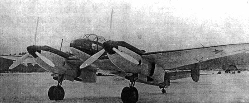
This aircraft, known as the Belyayev DB-LK, featured two fuselages, connected by a central wing section with a glazed rear cone. Despite its unconventional layout, testing showed that the DB-LK was a stable and reliable aircraft. However, the Soviet aviation industry at the time prioritized more conventional designs for long-range bombers with the onset of war, which ultimately doomed the project before it could progress further.
Belyayev DB-LK was an unusual twin-fuselage long-range bomber prototype. Source: Reddit
History
Following the end of the First World War and the later Russian Civil War, a new nation emerged from the remnants of a once-mighty empire: the Soviet Union. During the 1920s, it began the slow process of rebuilding its shattered industry. In order to recover, the Soviet political and military leadership decided to prioritize large-scale industrial development, and enormous financial resources, manpower, and raw materials were committed to achieving this goal. As a result, new technologies were quickly introduced, leading to a period of rapid industrial expansion.
The aviation sector also benefited from this renewed focus. A series of new projects, both civilian and military, were initiated to rebuild and modernize the nation’s air capabilities. Before the First World War, in the now-lost Russian Empire, there had been considerable developments in airliner design. However, progress was halted by the outbreak of the First World War, and the devastation caused by the subsequent Civil War. By the early 1920s, the aviation industry’s infrastructure was in ruins, and many of its original engineers and experts had either fled the country or been killed.
By the 1930s, new experts were eager to test various ideas and concepts. Among them was Viktor Nikolayevich Belyayev. Born in 1896 (Moscow, Russian Empire), Belyayev showed a strong interest in aviation from an early age and was an enthusiastic engineer. During the late 1920s, he worked with Andrei Nikolayevich Tupolev’s Experimental Design Bureau, and later with Aeroflot, the Soviet civil aviation operator.
Viktor Nikolayevich Belyayev was a Soviet aircraft designer and aviation enthusiast who was particularly keen on finding ways to minimize aerodynamic drag while improving overall flight performance. Source: en.wikipedia.org
Belyayev had a particular fascination with a bat-wing, sometimes also described as a butterfly wing shape, design, featuring a slightly forward-swept wing with tips that curved gently backward. At the time, aviation worldwide was marked by the introduction of numerous experimental and innovative concepts. With such rapid technological progress, there was plenty of room for improvement and innovation, and eccentric ideas found fertile ground for development. Belyayev believed that this bat-wing configuration could significantly improve longitudinal stability while also reducing overall drag.
Like many other aircraft engineers who often lacked adequate funding, he decided to test his ideas using simple and inexpensive gliders. In 1920, he built a fully operational glider. In 1933, he managed to construct a glider designated BP-2. It used the bat-wing layout and also featured an unusual twin-tail assembly connected by an extended elevator. The glider was tested in a flight from Crimea to Moscow, towed by a Polikarpov R-5. The tests were successful, which encouraged Belyayev to continue experimenting with new fuselage designs. He was particularly interested in an unconventional twin-fuselage arrangement.
The Belyayev BP-2 was used to test some of his concepts. It successfully flew from Crimea to Moscow while being towed in 1933. Source: airwar.ru
The Development of a New Project
Following his research and experimentation with glider design, Belyayev eventually felt that he had gathered enough knowledge and design experience to put his ideas into practice. In 1934, he began working on a new twin-fuselage, 10-seat transport aircraft. Each fuselage was fitted with a 750-hp engine.
In addition to developing new wing designs, Belyayev also theorized methods to significantly reduce aircraft drag. Conventional twin-engine aircraft had their engines mounted on the wings, which inevitably created drag that could not be eliminated. Belyayev’s new concept was to extend the engine nacelles and use them as the fuselage itself. This meant that no additional structural elements had to be attached to the wing, thereby removing unnecessary drag and creating a more aerodynamically efficient aircraft.
In the late 1930s, the Soviet Air Force issued a requirement for a new long‑range bomber. Belyayev decided to take this opportunity. He essentially reused his original civil aircraft design and adapted it for military use. In 1938, he approached the Soviet Air Force with his proposal for a new long-range bomber. This time, he received approval to construct a working prototype, which was completed rather quickly by November 1939. The resulting aircraft made use of his earlier concept: it featured two fuselages that, technically speaking, functioned more like elongated engine nacelles.
The aircraft received a simple designation: DB-LK. While not entirely clear, this was most likely an abbreviation of Dalniy Bombardirovshchik – Letayushcheye Krylo, meaning Long-Range Bomber — Flying Wing. It is also often referred to by its designer’s name as the Belyayev DB-LK. During the testing phase, it also carried the nickname Kuritsa (Eng. Chicken), given by the test pilot who was afraid to fly it.
Experimental Flights
Once the DB-LK prototype was completed, it was cleared for its first flight tests. While Belyayev may have had doubts about the realization of the entire project, he likely never expected that, despite the vast size of the Soviet Union, not a single test pilot was willing to fly his plane. At this time, most pilots were still flying older biplane designs, and many were often reluctant to test newer aircraft. For example, some even hesitated to fly low-wing monoplanes, which were still unfamiliar to many aviators. This hesitation stemmed both from a general fear of experimental aircraft and, to an even greater degree, from an ingrained belief that proven older designs were superior to new, untested ones. In any case, Belyayev unexpectedly found himself unable to secure a willing test pilot.
This situation dragged on until 1940. That year, the Soviet Directorate of the Air Scientific Test Institute issued an official order assigning pilot M. A. Nyukhtikov to test the aircraft. There was little point in keeping a fully functional machine sitting idle on the ground. To support the pilot during the trials, lead engineer T. T. Samarin and test observer N. I. Shaurov were also assigned to the project.
After several initial flights, Nyukhtikov reported that the aircraft’s controls were heavy and difficult to operate. In addition, he noted that the landing gear should be strengthened. A commission of the Scientific Test Institute, led by A. I. Filin agreed that the control system needed refinement but rejected the pilot’s concerns regarding the landing gear. This decision proved premature, as only a few days later, during a flight test involving Filin himself, one of the landing gear legs collapsed.
Despite test pilots repeatedly pointing out that the landing gear was too fragile, it ultimately took an accident for their superiors to finally realize that this was something that needed fixing and improvement. Source: militarymatters.online
Sudden End of the Project
After a series of test flights, the DB-LK, despite its unconventional, inverted-gull twin-fuselage design, proved to be an airworthy and well functioning aircraft. During testing, the DB-LK could easily reach speeds of up to 488 km/h (303 mph) at an altitude of 5 km (16,400 ft). When fully loaded, it was also capable of climbing to around 8.5 km (28,000 ft). In total, more than 100 test flights were conducted without any major incidents, demonstrating that the overall design was sound.
Complaints from the test pilots focused on the limited visibility experienced by both the pilot and the navigator. Despite this, the DB-LK was viewed as an aircraft with significant potential for future service within the Soviet Air Force.
Then, suddenly, the project was shut down. This occurred for several reasons, though not necessarily because of flaws in the design. By late 1940, war was raging in Western Europe between Germany and Britain, and a wider conflict seemed increasingly possible. The Soviet leadership did not want to take risks with an aircraft considered highly unorthodox. The DB-LK’s twin-fuselage layout likely contributed to these concerns. Instead, the authorities decided to focus production efforts on the more conventional and already-established IL-4 bomber. With that decision, all work on the DB-LK stopped. Its final fate is unclear, but it was likely scrapped.
Technical characteristics
The DB-LK featured an unconventional overall layout, lacking a traditional central fuselage. Instead, the crew stations, armament, and most of the onboard equipment were housed inside two elongated engine nacelles that terminated in glazed tail cones (gondolas), somewhat reminiscent to the aft section of the later German Fw 189. In practical terms, these extended nacelles functioned as the aircraft’s fuselage. Each semi-monocoque structure was built from a framework of metal frames and longerons, covered with duralumin skin. The two glazed cones could be mechanically rotated 360°, boosted by small electric motors mounted on top of the fuselages. This was designed to provide the best possible angle for the rear gunners, while retaining aerodynamic shape.
The DB-LK’s wings featured a distinctive layout. In addition to the characteristic “batwings,” the aircraft incorporated a central wing section positioned between the two fuselages. The wings were slightly forward-swept and ended in backward-curved tips. Structurally, they consisted of a light metal stressed-skin construction over a conventional airframe. The outer wing panels used a Göttingen 387 airfoil profile, while the center section employed a CAHI (TsAGI) MV-6bis profile. The wing leading edges were curved at an angle of –5° 42′.
The aircraft’s rather unusual wings were slightly forward-swept and finished with backward-curved tips. Structurally, they featured a light metal stressed-skin construction built over a conventional airframe. Also note the glazed rear fuselage cone section, where the rear gunner would have been positioned. Source: forum.warthunder.com
The rear tail assembly was mounted on the central wing section between the two fuselages. It consisted of a single vertical fin with a large rudder. Above the rudder, a small horizontal stabilizer was installed, fitted with two large elevators, one on each side.
The rear tail section was also unusual, being positioned in the middle of the central wing section and featuring a large rudder with a small tailplane. Source: wikipedia.org
The landing gear retracted rearward, with one wheel (900 × 300 mm) housed in each fuselage section. During later testing, this arrangement was redesigned, and the gear was modified to retract forward instead. The entire landing gear system was hydraulically operated. A small fixed tailwheel (450 × 150 mm) was installed at the bottom of the tail unit.
The DB-LK was powered by two Tumansky M-87B 14-cylinder radial engines, each delivering 950 hp. These drove three-bladed variable-pitch propellers. It was planned to replace them with the more powerful 1,100 hp M-88 engines, or even the 1,700 hp M-71, but these upgrades were never implemented as the project was ultimately cancelled. Fuel was stored in both the wing and fuselage tanks, with a total capacity of 3,444 liters (910 US gallons)..
Behind each of the two engines, a cockpit with a rear-sliding canopy was installed. The DB-LK was designed to be operated by a crew of four: the pilot, navigator, and two rear gunners. The pilot occupied the left cockpit, and the navigator the right. The gunners were positioned in the two rear glazed cones, with one of them also serving as a radio operator. Crew members entered their positions through the roof hatch doors.
Given its role as a long‑range bomber, Belyayev intended for the aircraft to have a fairly respectable defensive armament for its day, consisting of six machine guns. Both rear glazed tail cones were fitted with mounts for twin 7.62 mm (.30 in) ShKAS machine guns. These weapons had a firing arc of –10° to +10° in all directions. However, the gunner could rotate the glazed cones themselves, allowing him to reposition the guns and further increase the weapon’s effective defensive arc.
The interior of one of the two fuselages. On the right, the rear machine-gun mount is visible, while on the left side, you can see the radio equipment and the mechanism used to rotate the entire glazed tail cone. Source: forum.warthunder.com
In addition to these four rear-mounted machine guns, two more were installed in the leading edge of the center section and operated by the pilot. Altogether, approximately 4,500 rounds of ammunition were carried for all six weapons.
For attacking ground targets, bombs were to be employed. The bomb bays were located behind the landing‑gear doors in each of the nacelles. Each of the two bomb bays could carry up to 1 tonne (2,200 lb) of bombs, or alternatively four 250 kg (550 lb) or two 500 kg (1,100 lb) bombs per bay, four in total. In addition, a container with 59 smaller bombs could have been used instead. Lastly, an additional external bomb rack capable of carrying up to one tonne could be attached to the central wing section.
Cocnlusion
The Belyayev DB-LK is one example where the overall visual design essentially killed the project. The aircraft itself had no unresolvable flaws. In fact, it demonstrated generally good flight performance. It carried a large bomb payload, and its defensive armament, while not covering every angle, was still respectable. Most importantly, it did not suffer any major problems during the initial test flight phase.
Its main downside was its unusual overall appearance, which may have caused significant concern among industry decision-makers when it came time to consider a production order. It can be assumed that this was one of the key reasons it was cancelled, along with its prototyping being interrupted by the start of the Second World War. Soviet authorities preferred more conventional, proven designs and did not want to commit to a highly unorthodox aircraft that had no equivalent or prior service experience anywhere in the world.
Belyayev DB-LK specifications
Wingspan
21.6 m / 70 ft 10 in
Length
9.8 m / 32 ft 1 in
Wing Area
56.9 m² / 612 ft²
Engine
2x Tumanskii M-87B 950 hp 14 cylinder radial engines
Poland (1934-1939) Type: Light Bomber/Reconnaissance, Number built: 240
In the early 1930s, the Polish Air Force began modernizing its fleet as tensions rose in central Europe. Among its top priorities was acquiring a specialized class of aircraft capable of performing both reconnaissance and bombing missions. The goal was to develop a modern, all-metal aircraft that could fulfill both vital combat roles. This ambition materialized in the form of the PZL.23, produced in two main variants: the PZL.23A, and the improved PZL.23B. A total of 250 aircraft were built, and the design even achieved modest export success. These aircraft went on to serve in the early stages of the Second World War II, seeing combat against both Germany and the Soviet Union, with some measure of success.
The Polish Bomber/reconnaissance plane PZL.23 Source: https://en.wikipedia.org/wiki/PZL.23_Kara%C5%9B
History
At the start of the 1930s, the Polish Air Force was primarily equipped with outdated aircraft. This was the case with its bomber formations, which mostly relied on French canvas-skinned, biplane bombers, such as the Breguet 19. These aircraft were fragile, had a relatively small bomb-carrying capacity, and were intended more to harass the enemy than to inflict significant damage.
The role of the light bomber/reconnaissance aircraft was mostly taken by the French Breguet 19 biplane in the post war years. Source: https://commons.wikimedia.org/wiki/File:Samolot_Breguet_19_B2_NAC_1-W-1555-2.jpg
In 1931, the Polish Air Force initiated the development of a new bomber designed to provide close support to ground forces. In addition, it was also to perform the role of reconnaissance operations, this request being primarily based on the experience gained during the Russo-Polish War of 1919–1920. During that conflict, both sides employed a limited number of aircraft, mainly for reconnaissance and bombing operations. As a result, the Polish Air Force sought to replace its aging fleet with new aircraft capable of effectively performing both roles.
In 1931, the Polish Air Force issued a requirement for a new single-engine, monoplane aircraft. It was to accommodate three crew members and be capable of carrying several hundred kilograms of bombs, serving the dual roles of bomber and reconnaissance platform. Few proposals were submitted, including the high-wing PSW.19 and the Lublin R.XVII biplane. Of the two, only the PWS.19 was built and tested, but it was ultimately not accepted for service.
The PSW.19 was a proposal from Podlaska Wytwórnia Samolotów (Eng. Podlachian Aircraft Factory) for a new bomber/reconnaissance plane. However, the design was not accepted for service. Source: https://www.armedconflicts.com/PWS-19-t185849#valka_group-2
The winning design came from a young engineer named Stanisław Prauss, working at Państwowe Zakłady Lotnicze (PZL, or State Aviation Works). Prior to this project, Prauss had worked on the PZL.13, a single-engine passenger aircraft, which was a modern design for its time, featuring an all-metal structure. Despite its innovative features, the project was ultimately canceled in 1931.
Following that setback, Prauss and his team dedicated much of late 1931 to drafting design plans, and performing critical calculations for the new military aircraft. In order to accelerate development, Prauss chose to incorporate several elements from his earlier PZL.13 project into the new design.
To expedite development, Prauss decided to incorporate several elements from his earlier PZL.13 project. The overall shape of his earlier design was clearly reflected in the later production aircraft, including the fixed landing gear, engine configuration, and fuselage design. Source: http://www.samolotypolskie.pl/samoloty/2296/84/PZL-13
By early 1932, a full-scale wooden mock-up of the fuselage was completed. Both the drawings and the mock-up were presented to the Polish Aviation Department in the spring of that year. After analyzing the wooden construction and technical documentation, the department approved the project and ordered the construction of three prototypes for testing.The first prototype was completed by 1934, powered by a 593 hp Bristol Pegasus II M2 radial engine. Although not of Polish origin, the engine was produced under license in Poland, with the original rights obtained from the United Kingdom. The overall design was simple: a conventional linear crew arrangement with a weapons bay between them. The rear gunner was also expected to serve as the bombardier, for which a small under-fuselage compartment was provided. For defense, the rear gunner operated two machine guns, one mounted dorsally and the other ventrally. Lastly, another crew member was tasked with aiming and releasing the bombs. A forward-firing machine gun was also planned for the pilot’s use, though it remains unclear whether this was ever actually fitted to the prototype.
The prototype, designated PZL.23/I, was flight-tested in early April 1934. Interestingly, it received the nickname Karaś, meaning Crucian-carp, a species of fish. Its performance in the was rather poor, and several design flaws became apparent, such as a cramped interior, limited crew visibility, and vibrations in the rear section. Bombing trials were also problematic: when released, the bombs would shift from a vertical to a horizontal position, then back to vertical, as they fell from the aircraft. This erratic behavior significantly reduced bombing accuracy.
Further tests were carried out to refine the overall design throughout 1934 and into 1935. Eventually, the prototype was handed over to the Polish engineering college, where it was used for training new engineers. It remained there until the fall of Warsaw in September 1939.
The first prototype, although successfully flight-tested, was found to have several design flaws. As a result, after 1934, it was eventually repurposed as an instructional airframe.Source: https://jmodels.net/de-hombres-y-maquinas/aire-air/pzl-23-karas/
In late 1934, work began on a second prototype, designated PZL.23/II. The most notable change was the removal of the centrally located bomb bay. Instead, bombs were mounted under the wings, and the former bomb bay space was expanded to provide more space and improve visibility for the crew. Additionally, the engine was lowered by 10 cm to improve the pilot’s forward view. Other improvements included the addition of new leading-edge slats and flaps.
Testing revealed that many of the previously identified issues had been resolved; however, forward visibility was still considered unsatisfactory. Unfortunately, testing of the PZL.23/II came to a sudden and tragic end. At the end of July 1935, all three crew members were killed in a crash landing. The investigation concluded that the pilot had made a serious error, with some speculating it may have been a deliberate act of suicide.
Following the loss of the previous aircraft, another prototype (designated PZL.23/III) was constructed in 1935. This version incorporated several improvements over its predecessor, including an enlarged canopy and a raised pilot’s seat. These modifications significantly enhanced the pilot’s forward visibility, addressing a major flaw in earlier designs.
An especially interesting feature of the PZL.23/III was the addition of a hydraulically operated rear machine gun mount. This system allowed the rear gunner, if necessary, to engage targets approaching from the front by raising the machine gun above the forward fuselage. However, while seemingly innovative, this setup was likely difficult to use effectively in combat.
Production and Service Problems
Following the successful testing of the third prototype, the Polish Air Force placed an order at the end of 1935 for the production of 200 aircraft. These were to be manufactured at the PZL factory in Warsaw-Okęcie, with the first batch of 40 aircraft scheduled to begin production at the start of 1936. However, after only a few units were built, production was abruptly halted due to a critical issue: the unreliability of the Bristol Pegasus engines.
These engines, produced under license in Poland, were plagued by numerous mechanical problems that required extensive troubleshooting and rework. To make matters worse, the engines were not manufactured in the UK, which meant acquiring replacements or parts from abroad was not an option, given differences in manufacturing tolerances. It wasn’t until September 1936 that these issues were finally resolved, allowing production to resume. The aircraft entered service under the designation PZL.23A, and the initial order of 40 aircraft was finally completed in November 1937.
Unfortunately, matters only worsened once the aircraft entered operational service. The planes delivered to the Polish Air Force proved deeply disappointing, bordering on unusable. The engines were underpowered, limiting the aircraft to a maximum altitude of just 3,000 m. Additionally, the automatic leading edge slats frequently malfunctioned, often deploying mid-flight without warning and causing severe stability problems. As a result, the aircraft was ultimately deemed unsuitable for combat roles and relegated primarily to reconnaissance duties.
Need For Improvements
Abandoning the PZL.23 at that point would have seemed a waste of both resources and time, two things the Polish military could ill afford. Starting from scratch would have required significant time, with no guarantee that a new design would be any more successful. In the face of rising threats from both Germany and the Soviet Union, officials in the Polish Air Force sought ways to salvage the PZL.23 project.
One of the first PZL.23A production aircraft. Source: https://tvd.im/aviation/1666-pzl-p-23-karas.html
The first option considered was installing a stronger engine. PZL engineers decided to equip the aircraft with the newly produced Bristol Pegasus VIII engine, which had just entered production in Poland. This engine offered the advantages of its greater performance and a reliable local supply of parts, making it a logical choice. A prototype designated PZL.23/III was fitted with this engine and tested.
The third prototype was equipped with the new engine. Source: T. J. Kopanski PZL.23 Karaś
Although the speed increased only slightly (from 263 km/h to 274 km/h), the upgraded aircraft could now reach an altitude of 7.3 km, a significant improvement over the previous 3 km ceiling. In addition to the new engine, several other modifications were introduced: the leading-edge slats were removed, the elevator was redesigned, and an extended antenna mount was added to the observer’s gondola for in-flight radio use.
Lastly, the new variant received two machine gun mounts in the forward engine compartment, compared to only one in the earlier model. However, due to a shortage of available machine guns, only one was actually installed in most aircraft. With these improvements, production of the updated model continued under the designation PZL.23B (sometimes referred to as Karaś II). With the introduction of the B variant, the remaining A variant aircraft were mainly employed as trainers. Some of them were thus equipped with dual controls.
The most common variant was the PZL.23B, which resolved many issues with the previous model. Source: https://www-airwar-ru.translate.goog/enc/bww2/pzl23.html?_x_tr_sch=http&_x_tr_sl=ru&_x_tr_tl=en&_x_tr_hl=enNearly all PZL.23A aircraft were converted into trainers by rebuilding them with dual controls, as was likely the case with this example, which probably belonged to the training school at Krosno. Source: https://www-airwar-ru.translate.goog/enc/bww2/pzl23.html?_x_tr_sch=http&_x_tr_sl=ru&_x_tr_tl=en&_x_tr_hl=en
Production
After the production of 40 PZL.23A aircraft, the remaining 160 units were built exclusively in the upgraded PZL.23B variant, and the initial order for 200 aircraft was completed by September 1937. Due to high demand, the Polish Air Force secured additional funding and requested the construction of 50 more aircraft. This follow-up order was fulfilled by February 1939.
In total, 240 aircraft of the Variant A and B (in addition to three prototypes) would be built.Source: https://panssarivaunut.blogspot.com/2016/02/pzl23-karas.html
Experimental Project
Dive Bomber
While the PZL.23 shared some visual similarities with the German Ju 87 dive bomber, the Polish Air Force initially did not consider employing it in this role. However, by 1936, the idea of using the aircraft as a dive bomber began circulating among Air Force officials. To test the feasibility of this concept, one PZL.23A was modified to serve as a prototype, designated PZL.23/IV. This prototype could be easily identified by the removal of the bombardier’s gondola.
The proposed armament included two forward-firing and two rear-mounted machine guns. The estimated bomb load was 300 kg, though it was hoped that this could be increased to 800 kg for potential export customers. Testing was carried out by the Air Force Technical Institute (ITL) in August 1936. Despite the modifications, it’s overall performance did not improve significantly, and the aircraft proved unsatisfactory in dive-bombing operations.
PZL.42
In April 1937, the prototype was further modified by replacing the single vertical stabilizer with twin vertical tails. This change aimed to improve the gunner’s field of fire. Bombing trials conducted with this version were somewhat more promising. However, for unclear reasons, the aircraft remained at the prototype stage, with only one example ever built. It was later used as a training aircraft until it was destroyed in a bombing raid in September 1939.
The PZL.42 prototype was tested with the new tail design. Source: https://jmodels.net/de-hombres-y-maquinas/aire-air/pzl-23-karas/An aircraft lost in one of many German bombing runs during September 1939. Source: T. J. Kopanski PZL.23 Karaś
In Service
As the first PZL.23A aircraft became available, they were issued to units for familiarization. The first units to be equipped, in September 1936, included the 11th and 12th Flights of the 1st Air Regiment. The 21st Flight of the 2nd Regiment also received some of these aircraft. However, due to the poor performance of the PZL.23A, they were soon relegated to training duties.
With the introduction of the improved PZL.23B variant in early 1937, more than a dozen units received the updated aircraft. The Polish pilots experienced some difficulty adapting to the new type. This was not due to any inherent flaw in the aircraft or deficiencies in training, but rather because most pilots had been accustomed to flying older biplanes. This issue was not unique to Polish pilots—air forces across Europe faced similar challenges during this period of transition to more modern monoplanes.
Nonetheless, the aircraft was involved in numerous accidents. Between early 1937 and August 1939, a total of 23 aircraft were involved in various incidents, resulting in the tragic loss of 55 lives.
The PZL.23 would be dispatched in small groups of up to 10 aircraft to various units of the Polish Air Force. Source: https://en.wikipedia.org/wiki/PZL.23_Kara%C5%9B
In Action
Border Actions
The PZL.23 saw its first operational use against Poland’s neighbors in the year 1938, a particularly turbulent moment in this part of Europe. Nearly all the nations in central Europe had once formed much of the German and Austro-Hungarian Empires (including Poland), were embroiled in long-standing border disputes. These tensions escalated rapidly following 1938 as political pressure continued to mount across the continent.
Poland, eager to assert control over territories it considered historically its own, sought to occupy several neighboring provinces. In March 1938, a border clash between Poland and Lithuania triggered considerable alarm, prompting the partial mobilization of the Polish Air Force. However, the operation was poorly organized, hastily executed, and ultimately too late to have any significant impact.
To make matters worse, the relocation of several PZL.23 aircraft to an unprepared airfield near Wilno led to the crash-landing of three planes. By the 20th March, the brief conflict had subsided. Nonetheless, in an effort to intimidate Lithuania, the Polish military carried out a large-scale demonstration flight of over 100 PZL.23 bombers near the Lithuanian border.
The PZL.23 was deployed again in September 1938, this time against Czechoslovakia. At that point, part of Czechoslovakia had already been occupied by Germany with the approval of the Western Allies. Seeing an opportunity, Poland moved to occupy the Zaolzie region. Once again, the PZL.23 aircraft were used primarily as a show of force and did not engage in actual combat.
However, this show of force came at a significant cost. The frequent deployments accelerated the wear and tear on the PZL.23 fleet. Limited availability of spare parts meant that many planes had to be withdrawn from service due to being worn out beyond repair. As a result, some units were disbanded, while others had only a handful of operational aircraft of this type remaining.
Downfall of Poland
By July 1939, tensions between Germany and Poland had reached a boiling point, and the possibility of war between the two nations was becoming increasingly likely. In response, the Polish Air Force conducted several reconnaissance flights along the German border, primarily using PZL.23 aircraft.
On the 23rd of August, the Polish Air Force began mobilizing. According to Poland’s war contingency plan, in the event of conflict with Germany, the air force was to be divided into two main groups. One group would be placed under the direct control of the Polish High Command, while the other would be attached to various ground formations. By the end of August, nearly all PZL.23-equipped units had been mobilized and prepared for potential combat operations.
On the 31st of August, the Polish Air Force issued orders to implement the pre-war organizational distribution plan. The group under the High Command’s direct control consisted of five fighter flights and the Bomber Brigade. The Bomber Brigade included five flights of PZL.23 aircraft, which were at that point renamed Light Bomber Flights. These were supported by seven reconnaissance flights, each equipped with an average of eight PZL.23 aircraft.
The aircraft allocated to direct ground support roles for the army were dispersed in small groups across various units. Although in theory, they were meant to cover vast territories and participate in reconnaissance or bombing raids, in practice, this deployment strategy significantly reduced their effectiveness. Their numbers were too few in each location to have any real impact in combat.
As of 1st September 1939, the Polish Air Force could field only 114 PZL.23 aircraft. Of these, 50 were allocated to the Bomber Brigade and 64 were assigned to various ground forces. An additional 10 were held in reserve. At least 55 more aircraft were in storage awaiting repairs, and another 45 PZL.23s were being used as training aircraft. Some of these would be pressed into combat as a replacement when nothing else was available. The small number of available aircraft meant that the PZL.23 was a generally rare sight during the war in Poland.
Despite many misconceptions about the war, the belief that the Polish Air Force was destroyed on the first day, is simply not true. While many aircraft were indeed destroyed on the ground, many survived and saw continued use through the conflict. The PZL.23, in particular, saw considerable action in both reconnaissance and bombing roles.
The PZL.23s of the 21st Bomber Flight first entered combat on 2nd September. A single aircraft was tasked with locating a German column near Lubliniec. It successfully identified a German motorized unit and carried out an attack against it. Another aircraft was shot down while on a similar reconnaissance mission, having been engaged by four Bf 109 fighters. On September 3rd, the unit suffered further losses, with several planes downed by superior German fighters and anti-aircraft fire. By 11th September, the unit handed over its remaining four aircraft to the VI Bomber Squadron, and the surviving pilots and crew were evacuated to Romania. Between September 1st and 11th, the 21st Bomber Flight dropped approximately 10 tonnes of bombs and lost six aircraft.
The 22nd Bomber Flight saw its first action on September 3rd, attacking a German column. The bombers were engaged by enemy fighters and anti-aircraft fire, resulting in the loss of three aircraft. Two more were lost in a follow-up attack later that same day. Over the following days, the unit continued to carry out bombing raids against German forces. By 10th September, the 22nd had transferred its remaining aircraft to the VI Bomber Squadron and evacuated its personnel to Romania. By that time, the unit had dropped around 12 tonnes of bombs and lost a total of five aircraft.
A PZL.23B from the 22nd Bomber Flight, easily identified by the painted emblem of a flying dragon holding a bomb on the fuselage sides. Source: https://tvd.im/aviation/1666-pzl-p-23-karas.html
The 55th Independent Bomber Flight was another unit that saw heavy action in both bombing and reconnaissance missions. It was almost completely wiped out on 11th September, losing nine of its aircraft. Despite the losses, the unit managed to drop 14 tonnes of bombs in 40 combat sorties. The 64th Light Bomber Flight also suffered significant losses during the war, losing 21 aircraft to German fighters and anti-aircraft fire.
The 24th Reconnaissance Flight was engaged from the very beginning of the conflict, tasked with spotting enemy formations and tracking their movements. On the 3rd September, six of its aircraft took part in a bombing run against a German armored column near Rabka. Polish pilots reported scoring several hits on enemy targets, although one aircraft was lost to anti-aircraft fire.
Despite sustaining losses, the unit still had operational aircraft by the 14th September. The following day, one aircraft was assigned the dangerous task of delivering a message to the Polish High Command in besieged Warsaw. The pilot had to fly 360 km over enemy-held territory and land in a city under siege, with no guarantee that the airfield was still secure. Against the odds, the mission was successful. The aircraft even managed to take off again and return, despite German attempts to shoot it down. The unit remained active until 17th September, when it was forced to evacuate to Romania due to the Soviet invasion from the east.
The 41st Reconnaissance Flight operated a small number of improved PZL.43A aircraft (an export version of the PZL.43 that had been sold to Bulgaria). While most of these aircraft were delivered to Bulgaria before the outbreak of war, a few remained in Poland awaiting final delivery. Initially, they could not be used due to missing components.
Interestingly, on the 6th September, an element of this unit engaged a German reconnaissance balloon near Przasnysz. Despite being protected by anti-aircraft guns, the Polish aircraft managed to shoot it down. By the 10th September, the unit had only two PZL.43As remaining. On that day, during a reconnaissance mission, one of the aircraft was hit by anti-aircraft fire and crashed, killing its crew. The following day, the last remaining aircraft was damaged by an enemy fighter and subsequently lost in a crash landing.
A PZL.23B from the 41st Reconnaissance Flight. Source: https://www-airwar-ru.translate.goog/enc/bww2/pzl23.html?_x_tr_sch=http&_x_tr_sl=ru&_x_tr_tl=en&_x_tr_hl=en
By the time of Poland’s surrender on the 6th October, 1939, the PZL.23 aircraft of the Bomber Brigade had conducted over 186 sorties, during which they dropped approximately 64 tonnes of bombs. Meanwhile, the independent flight units assigned to the Army saw even more combat activity, flying around 260 sorties. However, these units dropped only about 20 tonnes of bombs, as their missions were primarily focused on reconnaissance rather than bombing enemy positions and forces on the move. Of the 140 aircraft deployed, over 100 were eventually lost in combat during the war. Far from the myth that the Polish Air Force was destroyed on the first day of the war, they fought with every tool at their disposal until the end.
By the end of the war in Poland, some 120 PZL 23 would be lost in combat. Source: https://www.reddit.com/r/WWIIplanes/comments/12bnmuw/german_personnel_examine_the_remains_of_a_polish/
In the Foreign Service
As soon as the first PZL.23 aircraft left production facilities, the Polish authorities were eager to generate foreign interest. In the spring of 1936, the PZL.23/III was presented at the air fair in Stockholm. Later that year, in November, another aircraft was exhibited at the Paris Air Show. Despite these efforts, Poland failed to attract any significant foreign interest in the design.
One PZL.23B was modified with a more powerful 925 hp Pegasus engine and equipped with a three-bladed, variable-pitch propeller. This variant was intended for export, but it failed to generate any interest, and was eventually reverted to the standard PZL.23B configuration.
The PZL.23B was modified with a 925 hp Pegasus engine, equipped with a three-bladed, variable-pitch propeller. Source; T. J. Kopanski PZL.23 Karaś
Bulgaria
The PZL.23 would see some export success. In March 1936, a delegation was sent to Poland by Bulgaria to evaluate and potentially acquire aircraft for their own use. Following a series of negotiations, Poland agreed to sell them 12 PZL.23 bombers.
However, the Bulgarians requested that the aircraft be powered by Gnome-Rhône engines, which presented a design challenge. The positioning of the Gnome-Rhône radial engines and their cylinders prevented the installation of the forward-firing machine gun originally housed within the engine compartment. Polish engineers had to overcome this by finding a new, suitable position for the machine gun within the fuselage, an issue that took some time to resolve.
By the end of summer 1936, the modified variant was ready. Due to changes in both the engine and fuselage design, the new aircraft was given a different designation: PZL.43. Although the contract between Poland and Bulgaria was signed on the 9th April 1936, actual production faced delays. The main issue was the engine: the requested Gnome-Rhône 14N had to be imported from France.
Bulgaria was the only country that showed interest in this aircraft, acquiring around 50 of a modified variant designated as PZL.43. Source: https://jmodels.net/de-hombres-y-maquinas/aire-air/pzl-23-karas/
It was not until May 1937 that the last of the ordered aircraft arrived in Bulgaria. The Bulgarians were satisfied with its performance and placed a new order for 42 additional aircraft. These were to be powered by the Gnome-Rhône 14N engine and received the new designation PZL.43A. Most of these aircraft were delivered by late August 1939.
Following the German occupation of Poland, the few PZL.43A units that had not yet been delivered were briefly tested by the Germans before being sent on to Bulgaria. In total, Bulgaria acquired 50 aircraft, comprising both the original PZL.43 and the updated PZL.43A variant.
During the war, these aircraft were primarily used for training purposes, though they were occasionally employed in operations against Yugoslav partisans. By September 1944, due to a lack of spare parts, most had been withdrawn from service. A few remained operational until 1946, when they too were finally scrapped.
Romania
Besides Bulgaria, Romania also operated some of these aircraft. They came into Romanian possession following the defeat of Poland in September 1939, when a group of 21 aircraft managed to escape German forces by fleeing to Romania. Of these, the Romanians were able to restore 19 to operational status, using the remaining two for spare parts. The aircraft saw extensive action against the Soviets, serving both in bombing, and reconnaissance roles, until 1943, after which they were reassigned to secondary duties. The last of these aircraft remained in service until 1946, when it was finally scrapped.
Romania operated at least 19 fully operational aircraft until 1943 when they were relocated for second line duties. Source: https://ww2aircraft.net/forum/media/a-crashed-pzl-23-karas-no-12-romanian-af.25926/
Germany
After their victory in Poland, the Germans managed to capture several PZL.23 aircraft, most of which were either in poor condition or heavily damaged. They repaired a few PZL.43s and used them for testing purposes. Beyond that, however, they showed little interest in these aircraft.
Germans tested some captured aircraft but showed little interest in them. Source: T. J. Kopanski PZL.23 Karaś
Soviet Union
The Soviets also managed to capture several PZL.23 aircraft, some of which were actually in working condition. These appear to have been put to some use by the Soviets; however, beyond that, nothing else is known about their ultimate fate.
Technical characteristics
The PZL.23 was a single-engine, low-wing aircraft intended for both bombing and reconnaissance missions. The fuselage featured an oval-shaped fuselage cross-section built using a framework of stringers and struts. The tail section employed a semi-monocoque construction for added strength and reduced weight. The entire fuselage was then skinned with duralumin sheeting.
An excellent illustration of the PZL.23 internal component and crew’s positions. Source: https://panssarivaunut.blogspot.com/2016/02/pzl23-karas.html
The wings were constructed in three main sections. The first section consisted of two spars that formed an integral part of the structure. In addition to serving as the attachment point for the rest of the wing structure to the fuselage, this central section also housed the mounting points for the two landing gear units. It was further reinforced to support a bomb rack installed beneath the aircraft fuselage.
Following this were the two outer wing sections, which were built using an innovative method. These outer parts featured a torsion box design, constructed with corrugated heavy-gauge duralumin sheets. These were connected spanwise by additional corrugated, stress-bearing duralumin plates with a smooth finish. Finally, the wing tipsand trailing edge slats were attached to complete the wing. The tail assembly was built using spars and ribs, all of which were covered in duralumin for structural strength and aerodynamic efficiency.
The wing was made up of three sections. The first section was directly attached to the fuselage and housed the landing gear and fuel tanks. This central section was flanked by the two remaining outer wing panels. Source: https://www-airwar-ru.translate.goog/enc/bww2/pzl23.html?_x_tr_sch=http&_x_tr_sl=ru&_x_tr_tl=en&_x_tr_hl=en
The cockpit was positioned at the front of the aircraft. In its early development phase, the PZL.23 suffered from poor forward visibility. This issue was eventually addressed in the B variant by lowering the engine and raising the pilot’s seat. Directly behind the pilot sat the observer and bombardier, who was provided with a glazed canopy offering fairly good all-around visibility. Beneath the fuselage was the bombardier’s gondola. Finally, at the rear of the aircraft was the gunner’s position
Close-up view of the aircraft glazed crew compartment. Source: https://panssarivaunut.blogspot.com/2016/02/pzl23-karas.htmlThe instrument panel. Source: https://jmodels.net/de-hombres-y-maquinas/aire-air/pzl-23-karas/At the bottom of the fuselage, a small bombardier’s gondola was installed. Source: J. B.Cynk The P.Z.L.23 Karaś
The first variant was powered by a 670 hp Bristol Pegasus II M2 engine. Later production aircraft were equipped with the more powerful 710 hp Bristol Pegasus VIII. In both versions, a two-bladed fixed-pitch propeller was used.
The fuel load consisted of 740 liters stored in six fuel tanks located within the central section of the wings.
The landing gear comprised two front-mounted fixed wheels (775×240 mm), each enclosed in aerodynamic spats. On many training aircraft, these spats were removed. To absorb shock during landings, shock absorbers were mounted on the landing gear legs. At the rear, a small tail skid with a shock absorber was installed.
The defensive armament included one forward-mounted 7.92 mm Wz.33 (Karabin lotniczy wz. 37) machine gun. The rear was protected by two 7.92 mm Wz.36 machine guns. Each machine gun was supplied with 600 rounds of ammunition. The B variant was designed to accommodate two forward-firing guns, but due to a lack of mounts, only one was typically installed. A ventrally mounted machine gun was also present, with an elevation and traverse range of 60 degrees.
For self-defense from rearward attacks, two machine guns were installed. Source: T. J. Kopanski PZL.23 Karaś
Initially, the aircraft’s bomb bay was located just behind the cockpit. However, during early testing, this design proved to be inefficient and was soon eliminated. Instead, bombs were mounted on an external rack positioned under the central fuselage.
This bomb rack could carry a payload ranging from 300 to 700 kilograms, typically using one of the following configurations: six 100 kg bombs, eight 50 kg bombs, or twenty-four small 12.5 kg bombs. In practice, however, loads exceeding 400 kg were rarely employed.
Production and Proposed Versions
PZL.23 I-III Prototypes – A small series of three prototypes
PZL.23A – An experimental version created by combining the Re.2002’s fuselage with the Re.2005’s wings. One built but never used operationally.
PZL.23B – possibly one modified for this role.
PZL.43 – Variant developed for Bulgaria
PZL.43A – Further improvement over the previous variant
PZL.23/IV – Proposed dive-bomber variant remained at prototype stage
PZL.42 – Future modification with new tail assembly, used as training aircraft until destroyed in September 1939,.
Operators
Poland – Operated fewer than 50 aircraft.
Bulgaria – Purchased 50 PZL.43 and PZL.43A aircraft, with a few remaining in service until 1946.
Romania – Acquired 21 aircraft from Polish pilots who escaped to Romania. Of these, 19 were put into service and used against the Soviet Union until 1943.
Germany – Captured numerous PZL.23 aircraft, though most were in poor condition. The Luftwaffe showed little interest in utilizing them.
Soviet Union – Also captured several PZL.23s, but there is no known record of their operational use.
Conclusion
The PZL.23 has developed something of an unfair reputation as a poorly designed aircraft. While it was far from perfect, it was not as ineffective as it is often portrayed. The aircraft did manage to inflict some losses on German forces, conduct many reconnaissance missions, and remained in service with Poland until almost the end of the campaign. However, like many of its contemporaries, it was too slow to effectively evade or counter enemy fighters. While capable in its designed role, it was adapted for various missions, some of which it was neither designed for nor particularly suited to, such as dive bombing, and it often flew missions without fighter escort. This left the aircraft highly vulnerable and with little chance of survival. Ultimately, nearly all PZL.23s were lost by the time the war in Poland came to an end.
Ponderous looking, yet agile, the G4M1 proved to be among the most dangerous weapons in Japan’s Naval Arsenal for early years of WWII. (SDASM)
Designed as a replacement for the aging G3M ‘Nell’, as a long range bomber and torpedo attack aircraft, the G4M represented a comprehensive improvement. In this plane, the Imperial Japanese Navy found a high speed bomber capable of carrying out raids, and engaging enemy ships at sea at otherwise unheard of ranges. During the campaigns in China, and first year of war in the Pacific, the G4M wrought havoc on Allied forces on land and at sea. However, its range and speed were achieved in sacrificing crew and fuel protection, and as the tide of war turned, the same design philosophy that gave the G4M its lethal edge, would see the crews flying the aircraft endure staggering losses.
The Road to War
The Imperial Japanese Navy rose to rapid prominence in the late 19th to early 20th centuries, alongside the equally rapid pace of Japan’s industrialization. Its victory against the Qing during the first Sino Japanese war saw them claim Korea and lay the ground for future Imperialistic inroads into continental Asia. Against Russia in the Russo Japanese war, they shocked the world after demolishing two major fleets and seizing Port Arthur, this being the first time a European country had lost to a non-european industrial power. The rise of Japan’s naval strength was a necessity of its mission, accepted since it first began industrialization, to expand its economic sphere and gain access to the necessary resources which home islands lacked. Oil, rubber, and ore were the foremost of its material needs, but there was also a desire to prove the racial superiority of the Japanese over the people of Asia, and rise above the Europeans and Americans who dominated the region. In the long term, this set the stage for brutal wars of expansion, conducted using the most advanced weapons available, over distances that dwarfed nearly every military campaign that had since been conducted. However, to fight such wars, the newest weapons of war and methods of manufacture had to be sought out.
The United Kingdom would prove an ideal partner in this, and would prove to be a critical source for military aid and equipment, and an alliance began in 1902, lasting two decades. Britain’s aim in this agreement was to ensure that the Russian Empire would not become a challenge to them in Asia. Among the earliest and most visible boons of the alliance was the Battleship Mikasa, purchased from Britain, and serving as the Japanese flagship during the Russo Japanese war. Over the coming decades, the exchange would bring invaluable experience, and modern equipment to Japan. By the end of the First World War, Japan had grown considerably as a naval and industrial power, with an economy now dependent on agricultural imports from continental Asia, and oil from Borneo and America. Their European colonial challengers were also diminished in number, with Russia’s navy diminished even further during the revolution, and Germany losing its Pacific and Asiatic holdings, to Japan’s gain.
Naval planners thus looked to new opportunities and conquests. The greatest of these was China, by then descended into warlordism, but an economic power nonetheless. By the start of the twenties, the Washington Naval treaty would affirm the integrity of Chinese territory in spite of the conflict there, and assure equal economic rights for those wishing to trade. While the Japanese government would maintain these two principles for the rest of the 1920’s, the Navy itself was becoming more dominated by voices seeking to challenge the treaty and other agreements as being strictly tools of European and American naval dominance and interests. A faction led by Vice Admiral Kato Kanji would hold to a different principle, asserting that “the United States, by its limitless economic resources, by its pursuit of policies of economic aggression, and, in China in particular, by its provocation of anti-Japanese activities, threatens the Japanese position in China for which our nation has risked its destiny.”
While Japan had yet to experience the era of political turmoil, assassinations, and the subsequent rule by the military, the roots of the eventual conflict with the US were found in the years after the Great War. In accordance with the anti-treaty faction, the United States was selected as the chief ‘hypothetical enemy’ when the nation’s Imperial Defense Policy was revised in 1923. Doing so not only meant challenging a materially and technologically superior opponent, but also claiming much of Asia for itself as a matter of industrial, and racial, destiny.
Building an Arsenal
To face the United State and European powers, modernization was paramount. In aviation, the greatest step came with the post-WWI Sempill Mission. While Japan had a nascent aviation industry which had begun development during the Great War, nearly every plane in use was imported, and what was domestically produced was of foreign design. As part of the last major exchanges in the dying Anglo-Japanese alliance, the Japanese Navy requested assistance in the field of aviation from the British in 1920. While there were major disagreements within Britain on such a technology transfer, the hopes for major partnerships and sales with the British aviation industry overcame such doubts. The mission arrived the following year, led by former RAF officer Baron Sir Williams Frances-Forbes, who had brought with him experts in aircraft design, construction, training, and use. Materially, he brought airplanes of nearly every type from fighters to torpedo planes, numbering over a hundred in total. The mission at Kasumigaura would prove to be nothing less than a spectacular leap for Japanese military aviation, putting it well on the path to self sufficiency. Combined with the Royal Navy’s advice on the construction of the Japanese aircraft carrier Hosho, the first carrier built from the ground up for the role, Japan would now possess some of the most essential tools in the wars to come. Just as the technical assistance ended, so too did the alliance with Britain, which lapsed in 1923.
By the end of the 1920’s, the Japanese Navy was a world leader in new naval theories, especially aircraft carrier development. Here the carrier Akagi sports a triple deck arrangement, which was soon done away with. (wikimedia)
The airplane industry grew slowly, first as a series of small shops producing a modest number of mostly foreign planes, but growing into larger enterprises. The largest of these manufacturers were Mitsubishi, Nakajima, and Kawasaki, which provided the nucleus for the rest of the cottage industry based aviation sector. Arguably the largest of these was Mitsubishi Heavy Industries, through its branch, the Mitsubishi Internal Combustion Engine Co. at Kobe. Concurrent with the Sempill mission, the company’s aircraft manufacturing effort was shifted to Nagoya, which would remain the center for Mitsubishi’s airplane development and production. In the years to come, additional production plants would sprout from the main facilities in Nagoya, with separate airframe and engine departments being founded by 1935.
While the aviation industry was slowly rising, the primary means of war against the United States navy was to draw in, and then attack the enemy fleet once it was deep within Japanese territory. It was hoped that through this single decisive engagement that any war could be quickly be settled, and thus Japanese supremacy over Asia was assured. It wasn’t until far later that the US would heavily outnumber the Japanese fleet, and serious changes would need to be made to this strategy. The general approach to this disparity was two contradictory schools of thought. The first was to overmatch the enemy on the technical and operational level, most clearly demonstrated in the development of highly effective oxygen fueled torpedoes, outranging the enemy with superior long range gunnery, and the development of keen night-fighting training. Against this program was the belief that any material disparities could be overcome by the superior, unique qualities of the martial spirit of the Japanese soldier, whose supposed unwavering morale and willpower could deliver victory against a better equipped enemy.
This strategy was entirely battleship focused until the thirties, with aviation playing a very small role until several crucial technical developments were rolled out. Aircraft at the time had a very limited range of action, small payloads, and were very fragile. Even though the Japanese Navy had been among the first to use aircraft in combat in the First World War, the airplane was seen as a tool for local defense and reconnaissance. Torpedo aircraft were particularly promising, but in a naval doctrine that required striking out with overwhelming force at long ranges, wood and canvas biplanes simply were not up to the task.
It was the development of all-metal, streamlined, monoplanes that proved to be the deciding factor in shifting the idea of the airplane as a defensive weapon, to one which could deliver deadly blows from afar. As the striking range of aircraft increased, so too did the potential range of the ‘decisive battle’, which by the late 1930s was planned for around the Marianas. As these technical developments progressed, Japan would find itself evermore under the influence of the military, whose factions would launch a war against China. They would seize Manchuria in 1932, and planned larger campaigns deep into the Chinese heartland. Given the vast distances involved, the Imperial Japanese Army and Navy sought new bombers with unprecedented range to reach targets over a thousand nautical miles away.
Rikko
The war against China, and the predicted war with America, would require the use of aircraft in roles that were restricted by available plane’s very modest performance. Crucially for the Army and Navy, by the mid 30’s, light and medium bombers were growing ever more capable, and Japan’s aircraft carrier program was world class. At this time, Rear Admiral Yamamoto Isoroku, the chief of the technical bureau of the Naval Aviation Department, was pursuing a program to achieve technical independence from foreign manufacturers. However, he had not merely wished for autonomy in aviation, but was interested in developing several new, critical weapons.
Among the first of these was a long range, land-based attack aircraft or, Rikujo Kogeki-ki. At the direction of Vice Admiral Matusyama Shigeru, Rear Adm. Yamamoto and his team were directed to research the requirements for a long range bomber capable of engaging targets with bombs or torpedoes in support of the battlefleet. With their findings, they approached Mitsubishi with the requirements for a new aircraft. This materialized in the Mitsubishi G1M, a modern twin engine bomber and reconnaissance aircraft. The experimental plane first flew in 1934 and was to provide the basis for a new bomber design.
The G3M was a thoroughly modern bomber, if fragile. It served to prove the viability of the long range torpedo bomber. (sdasm)
The new Mitsubishi G3M was developed by head designer Honjo Kiro. Much like the G1M, it was a sleek, all metal, twin engine aircraft. It had a range of 1540 nautical miles and an 800kg payload, presenting a very impressive level of performance for 1935. Particularly impressive was its range, which was beyond any other bomber save for the nascent Boeing B-17 under development in the United States. Achieving this range was largely a factor of streamlining, and some very extreme weight saving techniques. This included foregoing any protection for the fuel tanks and crew. Fragility aside, the aircraft was almost exactly what the Navy was looking for, with Captain Onishi Takijiro, head of the Instruction division at Koku Hombu, expressing great satisfaction with the new plane when he inspected the Kisarazu Air Group in 1936, this being among the first of the new Naval land attack units.
The G3M would serve the Navy well in China, where it attacked distant targets, being defensive positions, and cities, in an attempt to prevent their fortification and cow the Chinese government into capitulating. The bomber was as the Navy wished, but they found that it was extremely vulnerable to enemy fighters, given its lack of armor and modest defensive armament. Despite the experiences in China, and the heavy losses incurred, the Navy was largely disinterested in the succeeding design possessing any greater protection than the G3M. Instead, they requested a twin engined design with a maximum speed of 215 knots at an altitude of 3 km, a range of 2600 nautical miles, and a combat range of 2000 nautical miles. They did not request any increase in payload size, but the overall design requirements were extreme. Given the G3M was already a streamlined design, which required major compromises to its protection in order to achieve its speed and range, producing an aircraft some 27 knots faster and capable of flying 460 nm further would prove extremely challenging.
The G3M wrought destruction across China, from the raids on Nanjing and Shanghai, to the sustained bombardment of the city of Chongqing. (SDASM)
There would be no competition for the design, as Mitsubishi received the development contract directly from the Navy in September of 1937. Honjo Kiro would again be called upon to lead the design effort, though he would be in the United States until October of that year. Finding the Navy’s requirements for the new plane bordering on unreasonable, Kiro would instead suggest a four engined design, feeling the requested pair of 1000 hp Mitsubishi Kinsei engines being inadequate. During early design proposals with Naval staff officers, he would attempt to introduce a four engined rikko, but was angrily rebuffed by Rear Admiral Misao Wada, the chairman of the congress. The admiral, nearly losing his temper, shouted “The navy will decide matters of operational need! Mitsubishi should just keep quiet and build a twin engined attack aeroplane in accordance with navy specifications! Erase the drawing of the four engined aeroplane on the blackboard at once!”
Honjo was thus forced to return to the twin engined concept, and was also given a new requirement that the aircraft feature a defensive 20mm cannon at its tail. The list of requirements now completely eliminated the possibility that the new design could be a derivative of the previous G3M. Heading the team on his return to Japan in April of 1938, Honjo oversaw the program, joined by Kushibe Shiro and Hikada Tetsuro. He had the benefit of wind tunnel research conducted the previous December, but would have the unenviable task of designing to the Navy’s unchanged requirements. The G4M materialized as a bomber with a wide, but streamlined fuselage, built in two halves to ease production. Such was the diameter of the fuselage that visiting German engineers from Heinkel were confused that the wide bulkhead they were inspecting was for a twin engined aircraft. The wings were built incorporating a massive integral fuel tank between the spars, with the surfaces of the wings representing the other walls of the container. These massive, but unprotected, stores contributed much to the aircraft’s enormous fuel capacity.
Much to the relief of Honjo, he was able to argue for more powerful engines, shelving the 1000hp Kinsei radials, for the new 1530hp Mitsubishi Kasei. Aside from this reprieve, the design of the aircraft was a fairly chaotic affair, as the engineers at Mitsubishi were being reshuffled between the G4M, and the A6M Type Zero fighter under development by Horikoshi Jiro’s team. The first prototype would be completed in September of 1939, and was transported from Nagoya to Kagamigahara for flight tests, as Mitsubishi lacked a company airfield at their factory. It was first flown by Mistubishi test pilot Kazuo Shima on October 23, the tests revealed some issues with handling, but the aircraft performed well. Military trials were conducted at Yokosuka in early 1940, where it was joined by the second prototype. Both aircraft impressed the Naval staff there, with the plane well exceeding the requirements placed on it, reaching a top speed of 240 knots and possessing a range of 3000 nautical miles.
The G4M prototype, here sporting a ventral gunner position. (warfarehistorynetwork)
Unfortunately for the design team, these impressive performance figures inspired the navy to request Mitsubishi develop the G4M as a heavy fighter. They wished to provide a long range escort to the G3M squadrons in China, which were without air cover on deep raids. There were also concerns that switching to the production of a new bomber would result in too steep a drop in G3M supplies, and reduce the complement of squadrons currently deployed. The new G6M ‘wingtip fighter’ featured a reduced fuel load and a pair of 20mm cannons in a ventral pod. In any case, the new weight distribution of the aircraft ruined the good handling of the G4M, and it simply didn’t have the performance needed. Some 30 planes were built and shelved to later be converted into transport aircraft.
Pre-production of the bomber proceeded only after the futile attempt at converting it to a heavy fighter. In December of 1940, it would officially be designated the Type 1 land attack bomber, for the Imperial year 2601. In service, the aircraft was typically referred to either G4M, or more casually as Hamaki, or cigar, in reference to the shape of its fuselage. Among Honjo’s team it bore the far less flattering nickname of namekuji, or slug.
The model accepted for service was some 520 kg heavier, and some 9 kts slower than the prototypes, after the typical design modifications were made. It too now only had a range of 2315 nautical miles once it was at a full combat load. This was, however, more than enough to satisfy the Navy. They began receiving growing numbers of the plane as pre-production began at Mitsubishi’s No.3 aircraft plant, with these 13 planes proceeding mass production. Apart from some minor leaks in the integral wing tanks, the bombers entered service without issue on April 2, 1941.
Debut in China
The next war with China escalated from a minor border dispute into one of the bloodiest wars ever waged. By 1940, the Japanese Imperial Army and Navy had pushed into the Chinese heartland, seized many of the largest and most important coastal cities, and had taken the capital of Nanjing, leaving it unrecognizable after an orgy of violence. The Nationalist Kuomintang government was, however, resolved to continue the war by whatever means. Despite Japan’s air superiority, the Chinese Air Force stayed mobile and well outside the range of Japanese fighters. They could vacate their airfields quickly and inflict heavy losses on Japan’s bombers which had been despatched against their airfields, flying great distances without fighter protection. It was with the introduction of the high performance G4M, and the extremely long ranged A6M fighter, that this strategy was to unravel.
The key feature of the G4M was its phenomenal range, achieved through its wide fuselage stores, and integral wing tanks. (rodswarbirds)
The first G4M’s to see combat were part of the Imperial Japanese Naval Air Service’s 11th Air Fleet, formed in January in 1941. This force was composed mostly of the old G3M, but had received 30 examples of the new model bomber in July. They were to continue the aerial bombardment of many Chinese cities, beginning with Chengtu, but were soon to attempt the further destruction of the Chinese air force. The A6M fighters that had made their debut the year prior had the range to pursue targets deep within China, but were unable to hold formation with the old G3M bombers without weaving, reducing their range, and left them unable to follow them at night. However, the new G4M had a cruising speed that the fighters could match.
These two aircraft were thus essential to operation O-Go, a gambit intended to cripple the Chinese air force in some three months. The raids were launched in the early morning well before sunrise, with the bombers acting as the navigational leaders for the fighters, which kept the formation with the bombers in single-file. The force would then arrive at sunrise, to give little warning, and allow the bombers to attack as many of the grounded planes as possible, with those who were able to get off the ground being attacked by the A6Ms. The first attack was carried out on August 11, against an airfield near Ichang. The Chinese’s air force SB-2 bombers had scrambled, leaving two unserviceable planes to be destroyed, and had sent up fighters to break up the attack. To their surprise, they found fighters guarding the formation, one far more advanced than their Soviet-made I-153 biplanes. The Japanese fighters, and the gunners of the G4M’s, would claim five victories against the defenders, suffering no casualties themselves.
The operation, however, would be canceled as tensions with America and Europe had risen to the point of conflict. O-Go was suspended, but had demonstrated the long range strike abilities of the IJNAF, and the shocking capability of its long range fighter escorts. Against the bases near Ichang, the raiders had flown 47 miles further than the distance from London to Berlin. Such a feat would not be replicated until P-51B was introduced with the US Army Air Forces, and flown deep into Germany some three years later. These distances also show the long range character of the war to be fought across the Pacific, and explains the otherwise seemingly unreasonable range requirements requested by the Navy.
Setting the Board
While the Japanese invasion of China had at first been decisive, and horrifically destructive in its opening phases, their lines of communication stretched on, and the Chinese Army was growing into a more dangerous opponent. Relations with other powers with major economic interests in China collapsed, spectacularly in the case of the United States, leading to the cancellation of the US-Japan Commercial treaty. The concerns of European powers were growing too, but far less so in the face of the German-Soviet invasion of Poland in August of 1939. Meanwhile in Japan, the Navy’s ambitions were again stoked, remembering their own territorial gains of the last major war between the European powers. The most vital of these potential spoils were oil fields of Borneo, held by the forces of the now occupied Netherlands. This would grant Japan energy independence from the US, against which they had been planning an inevitable war for over a decade.
Planning and theory, however, were swept aside when the US imposed a total trade embargo in August of 1941, with the UK and Netherlands following shortly after. Rather than be an incentive to pursue diplomatic means, it instead drove the hawks in Japan’s military-dominated government to at last embark on a conflict it had long been expecting. The Imperial Japanese Navy and Army thus began working on the arrangements in what would be a rapid series of offensives across the Pacific that would wreck the American Pacific fleet before it had a chance to be mobilized, seize the vital defensive perimeter of Malaya, and oil rich colonies of the Dutch.
The G4M1 was to be a decisive weapon across the Southern Asian theater. As the carrier was to the attack on Pearl Harbor, the Rikko was to the offensive which spanned from Malaya to Borneo. (aviocampo)
In regard to the land based Naval Air forces, their task would be to decimate enemy air forces before they had a chance to strike at the fleets and armies that would soon take and occupy vast swaths of South East Asia. Squadrons of G3M and G4M bombers were thus based at Formosa, to strike the American Army Airforce in the Philippines, and from what was formerly French Indochina, to assault the British forces in Malaya. Of chief importance were two targets, the Royal Navy battleship Prince of Whales and battlecruiser Repulse, which were enroute to Malaya, and the large contingent of American aircraft based in the Philippines. From the 26 of November to the 7th of December, the Japanese Navy embarked on a silent offensive, as its fleets crept toward their targets in Thailand, Malaya, Borneo, Guam, and Hawaii. Even before the war was declared, bombers were enroute to attack their targets as part of an offensive that dwarfed all others in regard to time and space.
Bombing of the Philippines
The attack force set against the Philippines was the 11th Air Fleet, which had at its disposal 81 G4M bombers and a number of the old G3M, along with a complement of 90 A6M fighters. Based in Formosa, their targets were the American Army Air Corps’ Nichols and Clark’s airfields. The American complement at these bases was considerable, numbering 35 of the new Boeing B-17 bombers, and 107 P-40 fighter aircraft, for a total of 227 aircraft, representing a very modern, and heavy strike force.
The G4Ms would however, not be the first to attack, with the air wing of the aircraft carrier Ryujo having hit positions in Mindanao, to the South, and the Army’s bombers, hitting Luzon, in the north. Thick fog had delayed the launching of the December 8th attack, and the Nichols airfield mission shifted to attack the airfield at Iba. Clark airfield remained a vital target, with two waves of G4M’s departing under the commands of Commander Suda Yushio and Lt. Commander Nonaka Taro. Commencing several hours after the Pearl Harbor attack, the commanders led the Takao and Kanoya Air Groups up to an altitude of 7000m with their A6M escorts, expecting a grueling fight to the targets ahead.
The Kanoya Air Group would prove to be among the oldest and well accomplished of the Rikko units, playing a crucial role across the Southern Asian front. (SDASM)
When news of the war broke out, the commander of the Far Eastern Air Force, Lt. General Lewis Brereton, attempted to launch an immediate attack against the Japanese forces in Formosa, using his in all likelihood, inadequate 35 B-17s. However, when he attempted to receive permission to launch the attack from the theater commander, General Douglas MacCarthur, he was instead held up by the General’s chief of staff, Maj. Gen. Sutherland. Unable to launch the attack, and uninterested in rebasing his bombers to a smaller airfield which he felt was unsuitable for his formation which was soon to receive further bombers, he instead kept his aircraft prepared for the attack, and sent out an early morning fighter patrol as cover.
By the time the Japanese strike force was well underway, Brereton’s fighters were turning back home to be refueled. Observers would spot the massive Japanese formation, but all attempts to warn Clark field failed, its only hope now was were its cover fighters from Del Carmen field. However, dust storms had kept all aircraft at Del Carmen grounded, and thus Commander Suda’s forces came upon a perfect target. With much of the US FEAF’s planes cleanly lined up around Clark field, the destruction was swift and overwhelming. Bombs smashed everything from the planes parked in ready positions, to airbases facilities, with the anti-aircraft batteries trying to hit the raiders using old and defective ammunition, the most recent of which was produced in 1932. Only four P-40’s were able to get airborne, and were soon lost, with the Japanese A6M fighters descending and attacking targets that had escaped the bombers. The Iba attack was equally one sided, and also claimed the only working American radar station in the Philippines. In all, both airfields were knocked out, the B-17’s were lost, and about 24 of the P-40’s were written off with many more damaged, representing a combat loss of two squadrons. The Japanese would only lose 7 planes, the only bomber lost to a landing accident on its return home.
The timing and breadth of the Southern Asian offensive seemed almost unimaginable before the war. (campaigns of the pacific war)
The combined Japanese preparations, and the dysfunction of General MacCarthur’s command, had created a perfect storm that had largely annihilated the FEAF on the first day of the war. Even the staff of the Japanese Navy’s 11th Air fleet, Capt. Takahashi Chihaya believed, at the very least that, the B-17’s might have been rebased to the southern, and more defensible Del Monte airbase, which would have created serious challenges to the ongoing campaign to invade the Philippines. Few could have imagined the G4M’s strike could have been so decisive.
Force Z
While the FEAF was no longer mission capable, the next greatest threat in Southern Asia were the British garrison forces in Singapore, who were largely a responsibility of the Japanese Army, and Force Z, a pair of powerful warships dispatched weeks earlier to strengthen the British position after Japan had seized France’s Vietnamese colony. A battleship and battlecruiser, they represented a massive boost to British capabilities in the region, though the carrier support they were to receive was lost when HMS Indomitable ran aground and was laid up for repairs. Before the war had begun, these ships were merely intended to dissuade the Japanese from threatening Malaya and Singapore, as most of the Royal Navy was still tied down in Europe and the Atlantic. With the mission of deterrence gone on the morning of December 7th, the force’s commander, Admiral Tom Phillips, decided to take the most aggressive plan of action possible and attempt to thwart Japanese landing operations. Rather than choose to remain a fleet-in-being and attempt to shore up the defense of Singapore, or wait and attempt to merge with the joint Dutch-American naval forces, the Admiral gave the order to deploy his battleship, battlecruiser, and four destroyers into the sea of Siam.
The extreme range of the G4M1 allowed the IJN to strike at many targets once believed to be at a safe distance. Many western observers believed it to only have a range comparable to their own twin engine bombers. (sdasm)
It may seem foolish to have charged out without dedicated air cover, but until then, no heavy warship had ever been sunk by air attack, and he would have been out of range for nearly any other conventional torpedo bomber. The Royal Navy’s experience in Norway the previous year only reinforced this, as while German bombers had damaged several Allied cruisers, none had been lost. Beyond this, the airfield at Kota Bharu that would have supported him had been overrun by the rapid advance of the Japanese Army down the Malaysian peninsula. The Japanese Navy too had been landing marines down the coast, and when the Admiral received word at midnight December 9th that a landing force was unloading its forces at Kuantan, he set course to catch them at sunrise the next day.
As one of the Japanese Navy’s primary targets, Force Z was under considerable surveillance even before the war had begun. When they sortied on the 8th, Vice Admiral Osawa Jisaburo, the commander of the Southern Fleet, gave the Rikko units the mission to find and sink Force Z. Unable to pursue them the following day due to bad weather, the British fleet was spotted by submarine I-56 and its position was relayed to bombers. The next day, three Chutai comprising 88 planes of both the new G4M and the older G3M, launched at 06:44, to find and sink HMS Prince of Wales and Repulse. Most of the force carried torpedoes, with the 27 G3M’s carrying armor piercing bombs. Force Z was again discovered by a Genzan Air Group Rikko, and when they were joined by the bomb-laden Mihoro units, made the first attack on British warships. The attack began in a text book fashion, with a high altitude unit carrying out a level bomb attack while the torpedo aircraft made their attack runs in the confusion. 9 G3M’s dropped strings of bombs on the warships, scoring one hit, while 16 G4Ms carried out their torpedo attack. One bomb struck Repulse amidships, with the rest sending up torrents of water around the heavy warships in a shower of near misses. Some ten minutes later, the G4Ms carried out a multi-direction ‘hammer and anvil’ attack against HMS Prince of Whales, and despite the intensive evasive maneuvers, one torpedo struck the battleship on its port aft section. The explosion disabled its portside propellers and caused water to surge up the shaft into the portside engine space. With the battleship now flooding and navigationally impaired, the Japanese bombers departed, leaving the British warship in a poor state while the next attack wave assembled.
The G3M’s carried out level bombing attacks on the two warships, while the newer bombers carried out torpedo runs. The assault would comprise elements of the Kanoya, Genzan, and Mihoro Air Groups (Wikimedia)
With the position and course of Force Z relayed, the assembled formation now turned to engage them, with Lt. Cmdr. Shichiso Miyauchi as formation leader. Even with the information on the position and course of the British fleet, they were still hidden by low cloud cover. When they reached the reported position, Lt. Cmdr. Shichiso spotted a seaplane launched from the HMS Repulse and gave the order to descend through the clouds. The bombers found themselves 11 nautical miles away from the British force, HMS Prince of Wales showing a list.
The Lt. Cmdr. lead the first 9 plane Chutai against HMS Prince of Wales, which in response increased its speed to 28 knots, and began veering to starboard. The second and third divisions of this force were unaware of the damage the battleship had sustained, and set course to anticipate it making an evasive maneuver to port. When this never came, they broke off and went for HMS Repulse. This left Lt. Cmdr. Shichiso’s 3 plane unit to deal the finishing blow. He ordered the plane’s pilot and co-pilot to refrain from releasing the torpedo until they were within 500 meters of the target, then his plane and the number 3 aircraft, dropped their torpedoes, the second having lost sight of the target through heavy anti-aircraft fire. HMS Prince of Wales was struck on the starboard bow, and below the bridge. Now mortally wounded, most of the formation turned its attention to HMS Repulse.
Unlike the battleship, HMS Repulse was mostly undamaged, and taking extreme evasive maneuvers in an attempt to throw off the attack of six incoming torpedo bombers. Well trained against evasive targets, the Rikko approached from both sides and all but one plane launched their weapon was released, the battlecruiser taking a hit on its port side. The plane that was unable to make its attack then turned its attention to the HMS Prince of Wales and launched its torpedo, striking the battleship on its aft starboard side.
The second Chutai, under Lt. Higashi was next, dividing its attention between stricken British warships. They succeeded in striking HMS Prince of Wales again, though failing to hit Repulse, as it maneuvered through the spread of torpedoes launched against it. The last strikes came from Lt. Haruki Iki’s Chutai, and after an appraisal of the two damaged ships, decided that HMS Repulse was the more important target. Lt.Haruki’s plane led the attack from an altitude of 30m, nearly grazing the ship as he passed it. With both of his wingmen going down in flames from anti-aircraft fire, but their torpedoes launched, Lt. Haruki’s shotai scored three hits on Repulse, with the opposing side of the attack scoring one hit as well. The order to abandon Repulse was given at 12:30 with the ship quickly succumbing to flooding, this quick decision allowing several hundred men to escape the ship before it capsized. HMS Prince of Wales went down about an hour later, taking with it Captain John Leach, and Admiral Tom Phillips.
For the Japanese airmen, only four aircraft had been lost and they had proven a decisive lesson which all Navies were quick to learn, ships without air support were in mortal danger from aircraft. While theoretically, it had seemed possible a capital ship could be sunk from the air, this was the first time two such warships had been sunk in true combat conditions. Not only had the Rikko crews proven air power was now the deciding factor at sea, but in a strategic sense they had cleared the sea of Allied capital ships from India to Hawaii, and the IJN could land troops along the coast without fear of ambush.
Lt. Haruki’s two wingmen were the only aircraft losses with fatal results, with one G3M crash landing on its return to Vietnam, and four more planes needing a great deal of repairs. On his next flight over this area, the Lieutenant dropped two bouquets over the scene of the battle.
The Attack on USS Lexington
While the Rikko enjoyed great success in the early days of the war, one encounter would prove to be a sign of the difficulties to come. In the opening weeks of the New Guinea campaign, a task force centered around the fleet carrier USS Lexington was preparing to raid Rabaul, a newly captured Japanese Naval anchorage which would prove pivotal to the Japanese thrusts into New Guinea and the Solomon Islands. Detecting the force at long range, the 4th Air Groups was given the task of intercepting it on February tenth, 1942. 17 G4Ms were sortied in two groups against the task force, but without fighter escort, as the A6M units available lacked the necessary external fuel tanks needed for the mission. Led by Lt. Cdr. Ito Takuzo, they carried an armament of bombs. Detected, and set upon by Lexington’s fighters, several of the bombers were downed before having the chance to attack their target. The remaining aircraft of both units scored no hits.
The Lt. Cdr’s foiled attempt at Jibaku, or self destruction with the intent of dealing a blow to the enemy, his plane was struck by anti-aircraft fire as it neared USS Lexington. (WW2DB)
Lt. Cdr. Ito’s aircraft was badly damaged, one engine being entirely shot away by an American fighter. In their fatally damaged plane, the crew then attempted to try and fly into the USS Lexington. However, on the approach, their plane was riddled by anti-aircraft fire, and sent flying into the sea. In all, only two aircraft of the attack force were able to make it home, showing that unescorted attacks on ships with fighter cover were unlikely to succeed, and could only be made with extremely high casualties. Over succeeding campaigns, it would not be a lesson that would be taken to heart.
Battle for Port Moresby & The Bombing of Australia
While the IJN’s Fast Attack Force failed to eliminate the American Carriers in the Pacific, the loss of the American Battlefleet was a catastrophe, one that would allow the Japanese to advance swiftly through the central and southern Pacific. MacArthur would flee the Philippines, and Lt. General Arthur Percival would surrender Singapore, both after botched attempts at defending their territories. The Japanese Army and Navy would surge south, capturing rubber plantations, and the crucial Borneo oil fields. During this southern advance, the G4M would play a crucial role, in suppressing the RAF around Singapore, engaging American shipping around the Philippines, and harassing the joint American-British-Dutch-Australian cruiser force before its first, and only battle with the Japanese fleet.
With the vital resources of the Indies secured, the goal of the next phase was to build a defensive perimeter around the heart of this vast stretch of newly conquered territory. The next target was the anchorage of Port Moresby in Southern New Guinea, which if captured, would prove an excellent stronghold which directly threatened Australia. Before the carrier battle of the Coral Sea, G4M units were providing support to the amphibious landings in New Guinea. Lae and Salamaua were the first to fall in March, with the campaign continuing until the entire northern coast was held by the Japanese Navy. These operations would continue without challenge until the forces at Port Moresby were reinforced, first by a P-40 equipped squadron of the RAAF, and later by an American squadron flying P-39’s.
Against the defenders were the 4th and Tainan Air Groups.Their target was Port Moreseby itself, hoping to harass shipping and deplete the air strength of the defenders. The first major aerial engagement occurred on April 6th, where 7 G4M’s encountered five Allied fighters, surprisingly none were lost, though five returned with damage, and the loss of one crewmember. This encounter aside, the bomber units launched near daily raids against the Allied stronghold through May, even after the invasion force had been turned back after the Battle of the Coral Sea. After mid May, they sought to replenish their numbers, and returned to Port Moresby on June 16th, in support of an upcoming overland campaign by forces on the other side of the island.
Morale among the Rikko crews was exceptionally high after the initial victories across Southern Asia, remaining so until the Solomons. (rodswarbirds)
The loss of the four fleet carriers at Midway sent a shock through the entire Japanese war effort, and while it was not the fatal injury, or turning point, as it commonly seen, it forced a complete re-evaluation of how the war was being fought. In the shake up, many of the Rikko were redeployed, leaving the 4th and the Genzan Air Groups to continue the offensive at port Moresby. They would continue the bombing of Port Moresby, notably sinking the Australian transport ship Macdhui on the 18th of June. Air losses to enemy fighters were fairly light, as the bombers were given a considerable number of A6M fighters as escorts, and the night raiders met no meaningful resistance. Attrition was nonetheless an issue, as the Rikko were also tasked with the double duty of maritime patrols, which saw the men and machines of these units considerably overworked. While they had not demolished the Allied air forces in the region, the landing at Buna on the opposite side of the Island had succeeded, preparing the way for the Kokoda track campaign.
Concurrent with the operations to suppress Port Moresby were the raids on the city of Darwin, Australia, and its surrounding airfields. The first of these raids were unopposed, with the Takao Air Group flying over Western Australia in mid March. Their first encounter with enemy aircraft came on the 28th, during an unescorted raid by 7 G4Ms on the RAAF base at Darwin, which sent up a number of the American P-40E’s based there. They claimed one of the bombers, which returned the next day with nine A6M’s as escort, and bombed the airfield again without resistance. Hoping to keep up the pressure, the remaining aircraft of Takao Air Group returned from their mission in the Philippines, to the new base in Celebes. There they would launch the largest raid against Darwin on April 25th, with a force of 36 bombers and 15 fighters. This time however, the formation was met by a force of some 50 P-40’s, which claimed 6 bombers. In spite of these losses, they returned the next day with a strengthened 21 plane escort, seeing only the loss of one bomber. These raids saw a brief respite in May, before the Takao Air Group again made its appearance, bombing the city of Darwin with some 27 bombers on the 13th of June, suffering no losses. Having conducted the raid from a high altitude and with a large fighter escort, the P-40’s were unable to make the intercept. Losses remained low throughout the month, but given their position and strained resources, they switched to night bombing through the rest of the year.
Nocturnal nuisance raids remained the means of attack until March of the following year when the 753 Air Group launched a new series of daylight raids against Darwin. The first, launched on March 15, saw them target Darwin’s oil storage facilities with 19 G4Ms and 26 A6M’s. With the Australian air force having been substantially built up, the RAAF sent up a number of Spitfire Mk V’s. However, while they damaged some eight bombers, they suffered terrible casualties against the large escort force, and lost at least 14 of the new fighters. The IJN continued its assault on Darwin, focusing on its airbase, which had seen considerable build up. While they were generally successful against the RAAF bases at Darwin and Fenton, the slow accumulation of losses would see the last daylight raid flown on July 6th, 1943. The campaign was largely successful, as Darwin’s ability to host any significant naval forces was gone given its continued vulnerability to air attack, and the loss of its fuel stores.
Guadalcanal
With their homes now a warzone, these Papuan men became auxiliaries for the IJN (ww2incolor)
The loss of the fleet carriers Akagi, Kaga, Hiryu, and Soryu represented a grave loss for the Japanese Navy. However, it was not the decisive battle to end the war, as apart from the catastrophic loss of these ships and their airgroups, the IJN still possessed considerable offensive strength. The two most formidable IJN carriers remained, Shokaku and Zuikaku, and they were supplemented by the smaller fleet carriers Junyo and Hiyo, along with four light carriers.The IJN also retained its potent land based air arm. Against them were the American USS Enterprise, Saratoga, Hornet, and the smaller USS Wasp, along with a number of small escort carriers. While the United States could more than replace its losses the next year, if they suffered disastrous losses, like the one the Japanese Navy experienced at Midway, it could jeopardize Allied positions across the Pacific.
The area of greatest concern was the South Pacific, as while Port Moresby was still firmly in Allied hands, the Japanese Naval anchorage at Rabaul gave them control of the waters north of New Guinea. The Rabaul anchorage also proved a means of projecting force at the very edge of the Empire’s territory, which was soon to claim the otherwise unremarkable islands of Tulagi and Guadalcanal. In June, Japanese forces landed on these islands, and began the construction of an airfield on Guadalcanal. If completed, this outpost would give the Japanese Navy a powerful strategic position, allowing them to harass sea lines of communication from America to Australia. In a worst case scenario for the Allies, it could negate Australia as a position to build up forces for any major operation in the South Pacific. It would endanger the current operations to hold New Guinea, and force the main theater of the war from the Southern to central Pacific, where the Japanese Navy still held an advantage.
Before the completion of the airfield, the US Navy staged an amphibious assault with the First Marine Division going ashore on August 7th, with the support of a cruiser task force, the carriers USS Enterprise and Saratoga, and a screening force of sea planes for reconnaissance. This news came as a shock to the Japanese forces at Rabaul, with the first major response being a hastily assembled air raid of G4Ms of Rabaul’s 4th Air Groups. With such short notice, the Rikko were sent out with an armament of bombs, rather than switching to torpedoes before the 560 nautical mile flight. They flew out under the command of Lt. Egawa Renpei, a non-pilot officer, with 18 A6M fighters as escort, with one abort.
G4Ms of the Misawa Air Group (rodswarbirds)
The raiders were discovered first by coastwatchers, followed by USS Saratoga’s air search radar at 11:50. F4F wildcats from Enterprise and Saratoga were scrambled to meet them at 10,000ft. They met the bombers as they lined up on the cruiser task force, unaware of the presence of the American carriers. Under some disruption from the escorts, the Wildcats claimed two bombers outright, damaging another two which were lost to ditching. The raiders failed to claim any serious damage, and returned to Rabaul to prepare for an attack the following day. The 4th Air Group sortied 17 G4Ms under the command of Lt. Ikeda Hiromi, and were joined by a further 9 from the Misawa Air Group, for a torpedo attack on the American vessels at Guadalcanal. After several aborts, 23 planes flew to the target, joined by 15 A6M fighters.
With the American carriers having eluded Japanese reconnaissance efforts, the formation thus decided to attack the forces at the Guadalcanal beachhead. There they were met with a torrent of defensive fire from the task force’s cruisers and destroyers, and several wildcats from Saratoga and Enterprise. Only one torpedo found its mark in the destroyer USS Jarvis, and Lieutenant Junior Grade Takafumi Sasaki flew his fatally damaged bomber into the transport USS George F. Elliot, with the ensuing fire consuming much of the ship. In return, American forces would end up decimating the raiding force, which returned home with only five bombers and none of its officers, which would mark the highest losses for the entire campaign. Following the battle, the USS Jarvis would be found and sunk with all hands by patrolling G4Ms, and the George F. Elliot would be scuttled, its damage being too extensive to save the ship.
The Rikko pilots carried out attacks at extremely low altitudes, though often only the best of them would carry out the attack until the last possible moment. (WW2DBase)
The failure of the raid can be placed on the improved air defenses of American vessels, now mounting a considerable number of the 40mm Bofors guns capable of throwing out an enormous volume of fire, the presence of American fighter planes flown by aviators who had learned to fight the Zero, and also the decline of expertise of Japanese aircrews. One officer aboard the USS Astoria remarked that the Rikko of the 4th and Misawa air groups lacked the tenacity he’d seen in early battles, stating, “I’ve never seen them that bad before. Those crack Jap Navy pilots, the ones we tangled with in the Coral Sea, and at Midway–they don’t let up. Never. They come right at you, and they keep on coming until you get them or they get you. These punks–running away…”
While they had not faced the losses like the carrier based forces at Midway, casualty rates had been steady across the Southern Asian and Australian front, and the overly selective pilot training programs were now forcing these schools to rush students through to the Navy to try and meet demand. Pilots that went down in Rikko were also difficult to recover in the best cases, as their missions often took them to the limits of their own territory. In the case of the raid on October 8, 1942, those pilots who did survive took their own lives when the US Navy attempted to recover them. In the weeks to follow, many Rikko crews would refuse to bring parachutes, choosing to die, rather than bail out over enemy territory.
The day after the disastrous raid, a Japanese cruiser force would reach Guadalcanal, and in a night raid, destroy all but one of the American cruisers, and force the retreat of the amphibious forces, which had not had enough time to unload their cargo. The battle for Guadalcanal thus began in earnest, with the remote island being held by the First Marine Division against the Japanese 17th Army under Lt. Gen. Hyakutake Harukichi. Both sides were isolated on Guadalcanal, as the Japanese stronghold of Rabaul was nearly as distant as the American base at New Hebrides. The environment would prove dangerous, with malaria, dysentery, and dengue fever capable of sapping the strength of entire units, and the supply situation being so poor that some Japanese soldiers would begin calling Guadalcanal “Starvation Island”.
The Rikko would prove one of the only means of putting pressure on the now completed American airfield on the island, named Henderson for a pilot who had died at Midway. The naval air forces at Rabaul were also built up with the addition of the Kisarazu Air Group. Over the next few weeks, the assembled bombers would strike out at Henderson, with the first major raid comprising 23 planes against the airfield on August 25, suffering no losses of their own, as the American fighters were being used for ground support missions and were being rearmed when the bombers arrived. The next day, the Rikko returned with a strength of 16 planes under the command of Lt. Nakamura. Though suffering the total loss of two bombers, and two forced landings, the attack dealt a painful setback to the fledgling ‘Cactus Air Force’ at Henderson, as the bombers had torched 2000 gallons of avgas, and secondary munitions explosions damaged a number of planes. While they had escorts during these missions, the A6M’s had severe radio trouble due to their sets operating too close to the frequency of the faint radio emissions from their engine’s spark plugs. The fighter pilots typically opted to remove the troublesome sets to increase the range of their planes, but their situational awareness suffered accordingly.
The sheer size of the Solomon theater put the A6M’s endurance to the test. Most of the Rabaul Zeros had their radio sets removed due to onboard interference, and to further lighten the aircraft. Note the absence of the antenna aft of the cockpit (ww2db)
The raids would continue on a near daily basis, apart from a diversion to chase shipping around the area. For the most part, Guadalcanal was isolated, save for fast transports and deliveries by air. The Rikko claimed one of these transports on August 30th, sinking the USS Colhoun with a pattern of bombs. Heavy raids continued into September to support the Army on the Island, which would attempt to overrun the American positions in a night assault on the night of September 13-14. Defeated, the Imperial General Headquarters would reiterate that Guadalcanal was to be captured at any cost and placed more resources towards reclaiming the island. For the Rikko, this came in the form of two more Air Groups, the Kanoya and Takao, which had both arrived by the 23rd. This allowed them to rotate out the exhausted units at Rabaul, and continue the assault on Henderson.
Henderson however, had also seen some improvements. The Cactus Air Force was reinforced by USS Saratoga’s fighter squadrons while their carrier was sent away for repairs following an attack by Japanese Submarine I-26. They also had a new SCR 270 air search radar, set up in early September. They thus had a considerable number of Wildcats, and the ability to scramble them in time to the 8 km altitude the G4M’s flew. However, the radar system wasn’t perfect and could prove sensitive to the conditions on the ground. Sustained losses among the Rabaul’s squadrons grew considerably compared to earlier efforts. Naturally, daylight raids became less frequent, though they were still occasionally conducted and would inflict serious damage. On October 11th, a Japanese raiding force of 45 G4Ms under the command of Lt. Cdr. Nishioka Kazuo, departed to Henderson amidst poor weather. Several aircraft fell out due to the weather, but the remaining aircraft split into two units. As the first unit had completed its attack, the second made its way to Henderson and caught a dozen wildcats on the ground. They would return on the 13th, with Lt Makino Shigeji leading a 25 bomber raid on Henderson, this time failing to be intercepted due to weather obscuring the coast watchers. His force would set fire to a fuel depot, and destroy a B-17 on the ground.
The Kanoya Air Group was committed to the battle for Guadalcanal, during this deployment its fighter and bomber groups were divided, with the G4M1 units forming the 751st Air Group. (sdasm)
Night raids had begun in late August, and proceeded almost without end for a month. These were typically a single aircraft tasked with dropping a string of bombs on Henderson, with the intention of being disruptive, more than dangerous. As the conditions of the planes worsened, their engines began to grow desynchronized, leading to the aircraft making a terrible noise, earning these raiders the nickname ‘Washing Machine Charlie’. Contrary to popular myth, this sound was not intentionally created by mechanics tampering with the aircraft, the planes were simply badly worn out.
Fatigue, both of the air crews, and their equipment, resulted in the Rikko units being stood down for a time. Even with the reinforcements they had received, they had been pulling the quadruple duties of maritime patrol, anti-shipping, high altitude bombing, and night raider. From Rabaul to Henderson was about 565 nautical miles, which made for a flight time of about 6 hours. Near daily activity had rendered these units almost unserviceable.
The last major naval strike since the initial raid on the Guadalcanal came on November 12. Having detected a convoy of American ships, 19 G4Ms were sortied under the command of Lt. Cdr. Nakamura Tomo-o, who had an escort of 30 A6Ms. Led by Rear Adm. Daniel J. Callaghan, aboard the heavy cruiser San Francisco, Task Group 67.4 was primarily concerned with the presence of Japanese battleships in the area, but the air search radar on Guadalcanal informed them of an impending Japanese air attack. Detecting the force from over 100 miles away, they were able to vector a number of Cactus Air Force F4F and P-39 fighters to cover the formation.
Lt. Cdr. Nakamura brought in his formation just below the cloud cover, and after dividing his force into two units, sent them in after the American ships. As they did so, 16 American fighters rushed to intercept them. Keeping to almost wavetop height, the Rikko would attempt to press the attack while under heavy fire from the assembled American warships, and the enemy fighters which chased them frantically just over the sea. One unidentified F4F pilot went as far as resorting to ramming one of the bombers after his ammunition was expended.
Unlike the aviators that struck Repulse and Prince of Whales, many of the less experienced airmen were shaken by the volume of fire, and broke off their attacks as they closed in. None of the torpedoes hit their mark, but the pilot of one fatally damaged bomber chose to fly his plane into the USS San Francisco, rather than attempt to ditch on Guadalcanal. Anonymously, he flew his plane into the cruiser’s mainmast, the wreckage swinging over after impact, its pulverized engine and wing spilling burning avgas across the ship. The flames had spilled into the main battery director, and wrought havoc across the aft decks. In the end the fires were brought under control, but not before 22 lives were lost and further 22 were seriously injured.
USS San Francisco survived the air attack and played a crucial role in the first night of the Naval Battle of Guadalcanal the evening after the plane attack. It also suffered a good deal of friendly fire from another American cruiser. (USN)
Despite the Japanese aircrew having discarded their parachutes, committing themselves to death before capture over enemy territory, a number of survivors emerged from the wreckage of the low level planes. As boats were sent out to recover them, a bewildering series of encounters awaited them. One gunner aboard a floating wreck began firing on a nearby US destroyer in a very short encounter, an enraged petty officer aboard the USS Barton ignored the orders of his skipper and gunned down a dazed pilot climbing from a wreck, and one rescue team attempted to bring aboard a young airman, only to be prevented by his superior who shot him before turning the gun on himself. Of the 19 planes that were sent on the raid, only two returned to Rabaul in working order, two crews crash landed on Guadalcanal and later returned, and three others ditched in friendly territory. In all, 10 of the 19 crews were lost outright in one of the harshest engagements the campaign had seen. This all but decimated Rabaul’s attack force, leaving 3 of its 4 air groups in tatters.
Solomons
The greatest advantage of the G4M1 lay in its incredible range, but the sheer distance from Rabaul to the Southern Solomons proved grueling for near daily operation. (Dennis Burns)
The attempts to take the island of Guadalcanal failed, with the last major land battle occurring in late October, 1942. The now wearied Japanese Army clung to the South Western corner of the Island, where destroyers acting as fast transports left oil drums full of supplies, and brought in a trickle of reinforcements. At sea, the Japanese Navy had begun the campaign with a stunning victory off Savo Island, but in the months following, had lost the battleships Hiei and Kirishima in gun battles off the coast of Guadalcanal. Yet, they had managed to sink the American carriers, Hornet, Wasp, and critically damaged Enterprise, leaving Saratoga as the only American fleet carrier in the Pacific for some time. In return, they suffered the loss of the light carrier Ryujo, and the fleet carrier Shokaku had been seriously damaged, worse though, was the loss of experienced aircrews which the Navy’s training programs were struggling to replace. These victories would not be enough without Guadalcanal, the capture of which could have proven a decisive blow against the supply lines and, crucially, morale of American forces in the Pacific.
The Imperial Army Headquarters would finally admit the loss of Gudalcanal several weeks after the end of any serious engagements on the island, on December 31, 1942. The next year would see the American forces march further north in the Solomons, where they had once only had a foot hold. For the most part, the heaviest forces on both sides were spent, and USS Saratoga was too valuable to lose. It thus fell on the cruiser and destroyer forces to continue the battle for the Solomons. For the Japanese Navy, which had suffered the loss of a number of its heavier warships, it was hoped that the Rikko could partially take up their offensive ability.
During this time, raids to support the Army in New Guinea, to inflict losses on the Allied air base at Milne Bay, and nightly nuisance raids across the theater were carried out. Major daylight raids became very rare following last year’s losses, though this isn’t to say none achieved major success. One 23 bomber raid on January 17th destroyed numerous aircraft on the ground at Milne Bay, with no losses sustained. Regardless, some tactics were sworn off as far too costly, namely daylight torpedo attack missions. The combination of improved anti-air armaments on American ships, the slow, level approach of attacking planes, and the ever more present threat of fighters, thanks to early warning radar, made daylight attacks a costly, futile affair.
A switch to night attacks brought dangers of its own, but given the high level of blind flying ability of the more veteran Rikko crews, it was far from suicidal. They would soon prove their abilities on the night of 29/30 January, after a sizable force of American warships was spotted near Rennell Island. The force in question was a task force consisting of the heavy cruisers USS Wichita, USS Louisville, and USS Chicago, the only surviving cruiser of the ill fated battle of Savo Island at the beginning of the Guadalcanal campaign. They were joined by two escort carriers, three light cruisers, and six destroyers. However, the green commander of the force Rear Adm. Robert Giffen had steamed ahead of his slower escort carriers in order to make a timely rendezvous with a number of destroyers, before reaching Guadalcanal.
Lt. Cdr. Nakamura commanded the G4M’s sorties against this fleet, comprising a mostly veteran force from the 705th Air Group, and was joined by 15 older G3M bombers from the 701st. Departing before dusk, Nakamura led the formation against TF 18. The bombers of the 705th made their attack at 19:19 hours, in dim light. The G4Ms made their attack free of interruption from enemy aircraft, but failed to score any hits. They had lost only one aircraft in the attack, which was remarkable as this battle marked one of the first uses of radar fused, proximity shells aboard American warships. At 19:38, the second force, composed of the older G3M bombers undertook their attack in darkness, with a spotter aircraft dropping a string of flares over the American fleet. The string of flares was dropped in the heading of the force, colored coded to denote the types of ships. Against the light of the flares, the 701’s planes went in. USS Chicago found itself in the sights of Lt. Cdr. Higai Joji’s flight, and after downing one of his ‘Nells’ on a torpedo run, the burning, floating wreck of the bomber now illuminated the cruiser.
USS Chicago found itself at the center of the enemy attack, with the oncoming bombers scoring two hits, one hitting the after engine space and disabling three of its four propeller shafts and flooding its turbogenerators, and another striking the forward engine room destroying the remaining active shaft, leaving the cruiser dead in the water. Swift damage control efforts set flooding boundaries and allowed the crew to save the ship for the time being. For the heavily damaged cruiser, two of Lt. Cdr. Higai’s aircrews were lost, including the veteran commander himself. However, the engagement was not yet over, as Rikko were now aware of the survival of the stricken cruiser and sought to finish it.
The task of sinking the USS Chicago lay with the 751 Air Group, a unit now composed mostly of new crews, who lacked the skills needed for the night attack the evening before. Nonetheless, they sortied 11 G4M’s under the command of Lt. Cdr. Nishioka. They found the USS Chicago under tow by the fleet tug USS Najavo at 16:10. Under escort from the other warships and F4F’s from VF-10, two of the bombers were lost before the run. However, the remaining aircraft pressed the attack and put four more torpedoes into the cruiser, with the four surviving bombers departing at as best a speed as they could make. Surveying the damage, it was immediately clear that the Chicago could not be saved, and the Navajo was ordered to cut its line. Some 20 minutes after the attack, the cruiser capsized, with the attacks having claimed 62 men. The destroyer USS La Vallette was also hit, though damage control efforts saved the ship, then taken in tow by the then available USS Navajo.
Through 1943 the fragility of the G4M1 became ever more apparent, but with no replacement in sight, and the desperation of the Navy’s position in the South Pacific, it remained an essential tool against the Allies.(SDASM)
While the battle of Rennell island again demonstrated the lethality of the Rikko, it was again another sign that daylight usage of the aircraft could not be continued without significant losses. It was also indicative of a growing problem that had now reached a tipping point, one that was being felt across all of Japan’s air forces. A vast gap in ability between the fresh and veteran aircrews was not only being felt in the capability of their units, but was forcing restrictions on mission planning. The inability for new crews to even perform the same tasks as the veterans in theater would not only prevent them from embarking on the same missions together, but would leave them relegated to more dangerous missions, unable to fly under the cover of darkness.
I-Go and the Death of the Admiral
Wishing to avoid an entirely defensive campaign, Adm. Yamamoto would commit his South Eastern forces to an offensive to shore up the position of Rabaul, and its defensive circle from Bougainville to New Guinea. In this offensive, carrier air groups were based alongside their ground based counterparts for attacks on enemy shipping and air bases through the region. The Rikko, with new replacements, were to take a center role in the offensive and resumed raids against Port Moresby. Despite only modest damage being inflicted across the theater, the operation was judged a success.
Admiral Yamamoto Isoroku salutes gathered airmen at Rabaul, shortly after this meeting he would board a G4M1 bomber to survey his forces on a nearby island. (Wikimedia)
It was to be entirely overshadowed by what was supposed to be a typical inspection of frontline positions. Adm. Yamamoto and members of his staff boarded a pair of G4M’s to view their positions on Balalle from the air. Not expecting to encounter any enemy forces, the pair of bombers flew to the island with a modest escort of six A6M fighters. Unbeknownst to them, American code breaking efforts had succeeded in discerning the Admiral’s plans, and 18 P-38G fighters were in route. Coming upon the flight, they ignored the fighters and went straight for the bombers before withdrawing. Overwhelmed, the escorts brought down only one of P-38’s that day, with both G4M’s being shot down.
Veteran pilot FPO1/c Tanimura Hiroaki was able to bring the second plane to the beach below in one piece, saving the lives of his crew, Vice Adm. Ugaki Matome, and Yamamoto’ chief of staff. However, the first aircraft was riddled with bullets and went down out of control, with the Admiral being struck with gunfire at the start of the attack.
The Admiral’s wrecked aircraft after its descent into the jungle. (warhistoryonline)
The loss of Yamamoto was not the blow as it has often been remarked, indeed, he was a keen strategist, but one that had made his fare share of mistakes. His talents could never have been relied upon to salvage the then rapidly deteriorating Japanese position across the Pacific. However, the lack of a central figure with his prestige meant that the war would be directed by officers that often did not fight the war according to a single, realistic plan. The Admiral’s passing was a key point in the war, marking the definitive end of the period where a strategy was pursued with clear aims that might bring the Allies to the negotiating table. It was a purely attritional battle now, one that they were not prepared to fight, and with no plan beyond hoping to outlast their enemies.
Clinging On
With the loss of Admiral Yamamoto and the retreat from Guadalcanal, the Japanese Navy was now on the backfoot. It still possessed a number of carriers, but the quality of their aircrews had declined considerably, and the American carrier force was being introduced to the new Essex class, along with the excellent new F6F fighter. These new carriers were arguably the most capable of any class produced during the war, with 7 being commissioned in 1943 alone, a figure larger than America’s entire complement of pre-war fleet carriers.
Rather than assault the stronghold of Rabaul directly, American and Australian forces moved to cut them off to the West and South. (campaigns of the pacific war)
Despite the losses borne earlier in the year, new Rikko units were deployed to bases in New Guinea and the Solomon islands, with training programs rushing to help cope with a now permanent shortage in personnel. By mid 1943, they were typically being used only for maritime patrol missions, with the Allied air presence across New Guinea and the Solomons having been considerably strengthened. Aided by the introduction of new models of fighters in the theater, like the F4U-1 Corsair, the P-40F, and P-38G, they were now ever more confident in their control of the air. They were thus able to deal serious blows to Japanese raiding forces, and were able to cover their own raiders with the long range P-38. Extremely high losses among the Japanese Naval Aviators had also seen a shift in strength across the theater that now saw the Army Air Force shouldering the majority of effort in the theater.
As the American forces climbed ever northward in the Solomon Islands, the Rikko were again called upon to help shut down their advance. Near the end of June, a major amphibious landing was threatening forces around New Georgia, and 26 G4Ms under the command of Lt. Cdr. Nakamura Genzo were sortied to attack the assembled task force. They located the fleet between Rendova and New Georgia, and found it covered by F4F and F4U fighters. Regardless, they pressed their attack with 10 bombers making their way to the fleet. They would succeed in putting one torpedo into the transport USS McCawley. It exploded in the engine room, killing 15 and cutting power to the ship, which would remain afloat until being mistakenly torpedoed by friendly PT boats later that evening. Casualties among the Rikko were again exceedingly high, with 19 planes being lost.
The American advance to New Georgia, and soon Vella La Vella, would enable them to base aircraft in a far more northern position in the Solomons. This directly threatened the Japanese air bases, Army and Navy, on the Southern and Northern ends of Bougainville, the largest and northernmost island in the Solomons. The Rikko were directed to support ground operations, bombing enemy field positions in daylight raids, and despite the considerable presence of their own fighters, casualties soon became too heavy, and after a raid on the 15th of July, were called off.
Recuperation lasted as long as September, when Allied landings along Northern New Guinea threatened the important air base at Lae, which covered oversea communication with New Guinea and the stronghold of Rabaul. The Rikko were sent to raid shipping in the area to stifle the invasion, but through the month achieved little damage. Their tactics were largely switched to anti-ship level bombing, which saw significantly lower casualties but little success, until the end of the month when desperation forced them to launch a daylight torpedo attack. Of the 8 planes sent to attack the landing forces at Finschhafen, only one returned to base with another aircraft ditching, with no hits being reported to any allied ships.
The encirclement of Rabaul had begun in earnest and it would suffer a major air raid on November 3rd, and in retaliation, Admiral Koga Mineichi would order an anti-shipping operation that would include a deployment of carrier air groups to aid their strained land-based counterparts. The Rikko would begin the offensive with a night attack on US shipping around Bougainville on November 8th. A composite flight of G4Ms from the 702nd and 751st Air Groups were committed to a night attack against the forces that had recently landed American forces on Bougainville. They would be joined by carrier based bombers in the attack, and succeeded in torpedoing the light cruiser USS Birmingham, smashing a 30 foot hole in its hull, aft of its chain locker. Regardless of a near miss from a dive bomber, a torpedo strike, and a second bomb which struck turret no. 4, Birmingham’s crew raced to stop the flooding and succeeded miraculously. In spite of the beating, the cruiser could still make a speed of 30 kts, allowing them to keep up with the rest of the formation, and avoiding the fate of the USS Chicago. Only two crewmen were killed in the attack, though many more were injured.
By 1943 the A6M was growing increasingly obsolescent. Designed around a light, low power engine, it had limited capacity for improvement. Against new American models, some exceeding 2000hp, it was at a decided disadvantage. (SDASM)
In spite of the cover of darkness, losses among the Japanese forces were high, with 7 G4Ms being lost. Much improved gunnery from the American ships was showing that advancements in radar direction, proximity fusing, and training, enabled them to match the feats of the night torpedo bombers. At 19:58 hours, USS Birmingham used its 5 inch gun battery to down a single G4M engaged in illuminating the task force at a range of 14,000 yards. Worse for the Rikko was that while some of the new crews were proficient enough in low light flying for night attacks, they could still find themselves overwhelmed when committing to the final run of the attack.
Rikko sorties continued the following days, with fewer losses, but also marginal success. On the night of November 12/13, the Rikko attacked Task Force 39 in 04:53 in the early morning. Three G4Ms were able to box-in the light cruiser USS Denver in a hammer and anvil attack, scoring a hit. Struck along the starboard aft engine room, Denver quickly lost propulsion and took on a 15 degree list. As damage control efforts continued, the cruiser was brought under fighter protection at six in the morning, and was able to retreat to safety. Two of the three Rikko that attacked the cruiser were shot down, with the successful strike being made by Lt(jg) Maruyama Hidezumi, whose plane returned home with 380 holes in it.
Another major attack was launched on the night of 16/17. During this sortie, SFPO Kobayashi Gintaro would succeed in torpedoing the USS McKean, a destroyer being employed as a high speed troop transport. When attempts to evade the torpedo failed, it struck starboard, aft of the rear magazine, which caused an explosion that cast burning fuel oil across much of the ship and the water around it. Sinking at the stern, the order to abandon ship was called well before the explosion of the ship’s magazines. Sixty four sailors lost their lives, along with a further 52 marines, with the survivors picked up by the other destroyers of the force.
These attacks imposed some losses against the forces invading Bougainville, but they were unable to stop the northern stream of American forces that were soon to capture the southern flank of Rabaul. Regardless of the extreme overclaiming of the Rikko crew, they were unable to deal significant damage to the amphibious forces, and were themselves taking serious losses in operations, which earlier that year, had guaranteed a good deal of safety. Eventually, the forces in Rabaul would be encircled and subjected to attack from attacks from the South and the West, before American carrier forces returned to the region in strength to deal an even greater blow. During this period, only the Rikko of the 751st remained in theater, but after a massive air raid in February of 1944, the remaining forces withdrew.
The Retreat
While 1943 lacked the intensive surface battles of the previous year, and saw no new major aircraft carrier engagements, it represented a string of serioust defeats for the Japanese Army and Navy. By year’s end, they had completely lost the ability to threaten the sea lines of communication from Australia to America, and thus any major strategic position that could threaten the ability of the Allies to continue the war in the South Pacific. Worse, they were now fighting a lost battle to retain control of Rabaul, with New Guinea being remarked as a hell on Earth from which men did not return, and their positions in the Gilbert and Marshall Islands now being reduced to the outposts of Kwajalein, Enwitok, and Truk. The central pacific strategy was also non-viable, as the American carrier forces had been more than rebuilt, and had a year to build up their air groups, now flying the F6F fighter as the fleet’s standard, which was now more than a match for the A6M. Even moresow, now that Japan’s veteran naval airmen were either lost, or rotated out. This would leave all remaining air-fleet engagements extremely one sided.
The Rikko played a minor role in defending the Gilberts and Marshalls, apart from the base at Truk. At the beginning of 1944, this anchorage would find itself under attack numerous times by American carrier forces. The greatest blow came on February 17th and 18th, when it came under major air attack. Under siege from five American fleet carriers, the operation would thoroughly wreck the Japanese Navy’s air presence in the region, and prove that the anchorage was too vulnerable for any major use in the future. While there was largely very little the forces in the region could do against the American forces, one G4M flying from Tinian would make a solo night attack against the fleet carrier Intrepid.
This single plane managed to evade attention and make its attack against the carrier. The torpedo exploded 15 feet below the waterline, causing flooding, and jamming its rudder to port. Navigationally impaired, the crew had to fashion a sail to steer the ship back to Pearl Harbor for several months of repairs.
Now well established, the Allies conducted raids across New Guinea and the Solomons. Here an A-20G attacks grounded aircraft at Lae 1943. (ww2db)
Future attacks would take this form, as these night missions were less likely to be detected, and the pool of aviators who could actually carry out these attacks remained small. In the early months of 1944, the Rikko continued to make these attacks in piecemeal throughout the Pacific in response to the ever growing offensive on the part of the American Navy. The naval bombers also made their attacks in response to major landing efforts at Biak and Palau, while also making opportunistic bombing raids, such as one on June 5th against the airfield at Wakde island. There, a pair of G4Ms of the 753rd Airgroup destroyed six aircraft and damaged 80 more at the crowded air base, with a follow up attack hitting the base with three bombers on the 8th. However, for the most part, the effectiveness of most of these operations were indeterminate, as the scale of their operations diminished.
They also found themselves fighting more determined resistance in the air at night, as the USAAF and the Navy had advanced their own night fighter programs. Over Guadalcanal, the USAAF would first employ the P-70, a thoroughly disappointing conversion of the A-20 attack plane into the night fighter role. It had neither the speed, nor service ceiling, to catch a G4M at the 7km they typically flew during their nuisance raids over Henderson, and only one or two kills were made with this model over the course of the war. Frustrated with the P-70, Henderson resorted to using searchlight guided P-38G’s, and even modified some aircraft to carry an air search radar in a modified fuel tank. The pilot workload of the P-38G was already considered burdensome by many pilots, and the new device only worsened the situation. Greater success was found with the Marine’s converted Lockheed Ventura night fighters in the convoy defense role, but it wasn’t until the deployment of the P-61 in late 1943 that the G4Ms could effectively be pursued at night. Several dozen victory credits were tallied on the P-61, with two of the six aces made on the model being in the Pacific theater.
The US Navy’s solution to night torpedo attacks came in a more convenient form, as radar equipped models of existing carrier fighters. These were initially F6F-3N Hellcats, which placed an air search radar on the wing, which they would use in the final approach to the target after being vectored in by a supporting ship. Later models would become available, with more powerful engines, and a pair of 20mm cannons supplementing their .50 caliber guns. Marine and Naval aviators would shoot down considerably more aircraft than their land based counterparts, though fewer of them were G4Ms, with the majority being light patrol aircraft being used to track American warships at night. As was the case with American improvements in radar directed gunnery, the presence of these advanced night fighters made the Rikko’s night attack missions considerably more dangerous.
Replacement
The G4M1 Model 11 had served well past its prime, and was relieved by the improved G4M2 Model 22. The new model had Kasei Model 21 engines, which were rated at 1850 hp, with water injection. It had a new wing incorporating laminar flow research, increasing its size and fuel capacity, without increasing drag. However, it did not receive additional protection to its fuel tanks, nor did it implement anything more than token protection for its crew. Its defensiveness was somewhat improved by the installation of an additional 20mm machine gun in a powered dorsal turret, replacing the top 7.7mm machine gun mount. Later models carried the Type 3 Ku Mark 6 search radar, to allow for better target acquisition on night torpedo raids.
The G4M2 is easily distinguished by its elliptical vertical stabilizer tip, the expanded nose glazing, and powered turret, which isn’t visible from this angle. (ww2db)
The old G4M1 machines were considered old and outdated, both by Americans, and the Japanese Navy itself. The airframe itself was also somewhat dated, but better engines had improved its performance, and it was being supplemented by a lighter twin engine torpedo bomber, the P1Y Ginga, or Galaxy. Nevertheless, the Japanese position in the war was irrecoverable. The Japanese assembled carrier forces would be decimated by the loss of so many airmen in the battle of the Philippine sea, and leave the navy without a coherent strategy. The battle for the Philippines would be fought without a strategy that could even hope to bring victory. Even in the planning stage, it was evident that the remaining Japanese Naval forces could not hope to prevent an American amphibious operation in the Philippines, and they would only arrive well after the invasion force had disembarked all of its forces and cargo. With no hope of actually preventing the invasion, or claiming a victory of any strategic importance, the remainder of Japan’s Naval strength was sacrificed at Leyte Gulf.
1945 was a bleak year that saw the near collapse of Japanese society. In this last year of the war, a new model G4M3 was produced, in order to serve as a host aircraft for a rocket propelled kamikaze aircraft. It reflected the futile stubbornness of those who lead the country, with the military unwilling to terminate the war until it faced a near total blockade of the home islands, the loss of the USSR as a possible intermediary for negotiating the end of the war when it invaded Manchuria, the firebombing of most major cities, and the atomic bombing of two.
Peace
One of the Bataan flights taxis alongside guards. (ww2db)
In an unlikely coincidence, the G4M1 would play a role in ending the war that it had been engaged in since the first salvos. A renovated G4M1, and a transport model of a converted G6M heavy fighter, were selected to ferry the Japanese delegation to the base at Ie Shima. Under direction from Gen. Douglas McArthur, both planes were painted white, and marked with dark green capitulation crosses, so as to make them unmistakable. They also flew under the names Bataan 1 & 2, in remembrance of the first major battle between the US and Japanese Armies, and the forced march inflicted on the Allied troops.
A veteran pilot, Lt. Sudo Den of the Yokosuka airgroup, was selected to lead the delegation to Ie Shima. They departed Kisarazu on August 19th, and were joined by a pair of American B-25 Mitchells of the 345 Bomber Group, and a B-17H search and rescue plane. The trip went without issue, and Lt. Gen. Kawabe Torashiro and the other 15 delegates deplaned, and boarded a Douglas C-54, which would fly them to Manila. With the war over, they returned via the same track, but with Bataan 1 undergoing maintenance, they all boarded the G6M. In spite of a forced landing near the Tenryu river due to a fuel leak, the delegation made it home safely.
The final service of the G4M was in dispersing the remaining Rikko air and ground crew. It was on August 23 that the remaining serviceable Rikko were assembled at Komatsu. From there, the planes flew across Japan to deliver the former air and ground crews to airfields where they could make the last leg of their journeys home.
In spite of the high losses incurred by these units for much of the war, there were a number of aviators who had survived the entirety of the conflict. Perhaps the longest serving of them was Lt(jg) Tsuneo Otake, who had begun his service in the older G3M over China, before transferring to the Genzan Air Group, where he participated in the campaign over Guadalcanal until he returned back to Japan in May of the following year. From there he joined a transport squadron flying the G6M. By the war’s end he had flown 3022 sorties and accumulated 5255 flight hours. Another veteran was Lieutenant, later Captain, Haruki Iki. Capt. Iki was a veteran of the attack on Force Z, and dropped a bouquet of flowers in remembrance for those lost in the days after the battle. He was also among those who survived the war, and would go on to start an association for Rikko veterans.
Handling Characteristics and Tactics
As a design that was borne out of extreme compromises, the G4M nevertheless proved an easy aircraft to fly. It was easily controllable, even in bad conditions, and very stable, presenting a lighter workload for the pilot. Both of these would prove essential for an aircraft designed to fly over exceptionally long distances, and from bases that would be plagued with poor weather. Overall, pilots regarded the flight characteristics of the G4M as dependable. The only major drawback to the design’s airworthiness was the lack of feathering propellers, which made bringing the aircraft back a more strenuous job that required considerably more corrective flying to cope with the increased drag.
Under non-combat flight conditions, there were five members of the crew seated in the cockpit. The captain, navigator, and radioman pulled double duty as gunners. (9gag)
Protection was very poor. The only armor plate aboard the plane protected the ammunition for the 20mm, and was judged to be so useless that it was almost universally removed from the plane. All members of the crew were vulnerable to gunfire, which given the near universality of .50 caliber guns among American fighters, proved deadly. Worse was the lack of fuel tank protection, or self sealing containers. These aircraft were equipped with CO2 flushed atmospheres beside the wing fuel stores, and CO2 extinguishers, but these proved unreliable in combating fuel fires. Later aircraft were given rubber sheeting on the underside the wings to give some degree of self sealing protection from flak and ground fire, but provided no protection from enemy aircraft. Ironically, structurally the aircraft proved very durable thanks to its forward fuselage and wings built as a single unit. It was fairly common for aircraft to come home on one engine or in extreme states of damage, just so long as there were no fuel tank fires.
Most of the defensive guns were not particularly effective at defending the aircraft. None of the gun positions were powered, and the forward 7.7mm machine gun had a very limited angle of traverse, in addition to proving difficult to move against the air stream. The rear gunner position was the exception, and featured a 20mm machine gun. It was called a machine gun as this was a naval aircraft, and the IJN considered the 20mm a small cartridge compared to some of the others in their inventory. This weapon could seriously damage a trailing fighter, but was somewhat restricted by its use of a drum magazine, the reloading of which was quite cumbersome.
The aircraft was often called ‘Hamaki’ by its crews, over its cylindrical fuselage, though it carried a darker double meaning when the aircraft’s flammability began to become well known. Subsequent names like ‘one shot lighter’ or ‘flying lighter’ accumulated as its service continued through 1942. The official American callsign for the aircraft was “Betty”.
The aircraft was employed in many roles, as a level bomber, torpedo bomber, maritime patrol plane, photo reconnaissance aircraft, and transport. The typical combat deployment was the Kokutai, or Air Group. The airgroup itself was the Hikotai, led by its Hikotaisho, and supported by its Hikokai, which represented all of the ground based personnel and equipment, which included transport aircraft. An air group’s command staff was a distinct element, not considered part of its Hikokai. Each Hikotai comprised up to 27 planes, with an airgroup capable of fielding multiple, and not needing to be of the same model, such that some units operated both bombers and fighters. In March 1944, the Hikotai were given much broader autonomy and were capable of deploying to bases distant from their original ground based Kokutai staff and ground crew, and attaching themselves to ground based services in areas they were redeployed to.
The largest combat formation was composed of 3, nine plane Chutai, which were themselves composed of 3, three plane Shotai. In combat, these units could be broken down into whatever size formation was needed. During torpedo attacks, the shotai would be divided into their own sections and could be used to attack a target from multiple directions, preventing them from evading. At a larger level, Chutai would conduct attacks separately, waiting to see the results of proceeding attacks, before choosing and committing a target based on the damage they’d taken.
Construction
Bulkhead diagram (G4M1 Manual)
The G4M1 Model 11, was a multipurpose twin engine bomber, and was an all metal, mid wing design. Its semi-monocoque fuselage was built as two halves, joined at the 24th bulkhead for ease of construction. The forward section was built as a unified wing-fuselage section, both to increase its structural strength, and reduce weight. The rear section was simpler, and its construction was given to other firms. Structurally, the aircraft made use of ‘extra super duralumin’, produced originally by Sumitomo metals before the war. It was an exceptionally strong material in aircraft design, and an area where Japanese aviation had forged ahead of the rest of the world. Once joined, the fuselage consisted of 38 bulkheads. At the nose was a glazed section for navigation, behind which there was a flat panel in the floor for aiming the bombsight. Several windows were installed along the nose for navigation and reconnaissance purposes. The cockpit was long, containing five crew positions, and doubled as an observation platform. The cockpit was equipped with radio navigation equipment and a level autopilot. The arrangement of instruments was somewhat unorthodox, with the pilot and copilot having non-identical sets of instruments on their respective sides. Notably, the copilot’s side lacks several navigational instruments, with the intent that he likely use the central panel which does have them, in the case of emergency. The fuselage carried a centerline fuel tank, along with a trio of tanks, which were situated in the fuselage and inner wing panel.
The aircraft’s navigator takes watch alongside the radioman. (aviacaoemfloripa)
The captain of the aircraft sat behind the pilot and copilot, and also doubled as the top gunner. The navigator sat at the rear, left side of the cockpit, with the radio operator sitting opposite him. Both of them also acted as the waist gunners in combat, with the navigator also being the bombardier. The cockpit and nose also doubled as watch stations for maritime patrol missions. The rear gunner was the only position without a secondary duty. It also was the only one with armor, with two small 5mm steel plates installed to protect the 20mm ammunition, but they were rarely kept aboard the plane.
The wings were built into the forward fuselage and were composed of an inner panel, outer panel, the engine mount, removable inner leading edges, and the flaps and ailerons. The wings were built incorporating an integral fuel tank between the spars, running from the fuselage to the end of the inner panel, with the surfaces of the wings representing the other walls of the container. These stores, combined with those in the fuselage, gave the aircraft a 4780 liter fuel capacity. External sections of 30mm rubber sheeting, installed from the 663rd plane onwards, provided a modicum of self sealing ability from punctures from below the aircraft. This added 300kg to the aircraft, reducing its speed by 5kts and reducing its range by 170 nm. The only other protective measures were flushing the compartments fore and aft of the wing tank with CO2, and adding CO2 fire extinguishers. The wings also contained a pair of two 150 liter oil tanks. The flaps and landing gear were electrically operated.
The tail section comprised a three section horizontal stabilizer featuring a center section embedded in the fuselage, connected to two outer panels. The vertical stabilizer featured a smaller, innerpanel, and a considerably larger outer panel. All of the control surfaces were equipped with trim tabs.
The Kasei 11 and 15 were fitted with metal Sumitomo, 3.4 meter, constant speed propellers. They began receiving prop spinners between the spring and summer of 1942. (arawasi-wildwings)
The aircraft was initially fitted with the Mitsubishi Kasei 11, a 42 liter, 14 cylinder radial engine which was rated at 1460hp at 2350 rpm, and had a full throttle height of 4.6km. It had a length of 1705mm and a height of 1340mm. It was replaced in March of 1942 with the Kasei 15, which incorporated a larger supercharger which improved its performance at higher altitudes. Apart from the supercharger, it was visually indistinguishable from the previous model. It produced 1420 hp at 2350 rpm, and had a full throttle height of 6km. Both used direct fuel injection and were equipped with a single stage, two speed supercharger, with the Kasei 15’s being far larger. Initially, there were only two exhaust stacks, but later models included one exhaust stack per cylinder.
Armament
The G4M1 had a bomb bay which could accommodate 800 kg of munitions. The bomb bay did not have retractable doors, but rather a removable fairing that was carried on the aircraft for reconnaissance, transportation, and ferry flights. The bomb load could consist of a single 500kg bomb, four of 250 kg bombs, twelve 60 kg bombs, and a variety of other devices, such as parachute flares, and target marking smoke. They were configured to use the Navy’s bombs, and with few exceptions were unable to make use of the weapons for Imperial Army aircraft. The suspension methods between the two forces differed, and their fuses were not interchangeable without the use of an adapter.
Ground crew maneuver a Type 91 aerial torpedo into place (rodswarbirds).
As with other Japanese torpedo attack aircraft, the G4M1 carried the Type 91 torpedo. This weapon was produced in a number of marks going back to 1931, though wartime stockpiles and production were the Models I, II, and III, possessing a common diameter. These had a diameter of 45 cm, and were powered by an eight cylinder, wet-heater type, radial steam engine. The Mod. It could carry a 150 kg warhead out to a range of 2 kilometers at a speed of 42 knots. The Mod. II, a 205 kg charge out to the same distance, with the Mod. III carrying a 240 kg warhead. The Mod.III also possessed an interchangeable warhead, allowing it to be converted to a Mod. IV, 300 kg, a V-Head 305 kg warhead, a Kite head at 355 kg, or the Mod.VII at 420 kg.
The Type 92 machine gun in its deployed position. (ww2db)
The bomber was equipped with three 7.7 mm Type 92 machine guns, and a single 20mm Type 99 machine gun. The Type 92’s were modernized variants of the British Lewis gun, being a gas blowback machine gun with a cyclic rate of 600 rounds per minute, and loaded from 97 cartridge pan magazines. The 20mm machine gun was an Oerlikon FFL adapted for an aircraft mount. It was an advanced primer blowback weapon with a cyclic rate of 490 rounds per minute. It could be loaded from 45, 60, or 100 round drum magazines. The 100 round magazines were a late war addition. The machine gun enclosures were two part blisters where the rearward half could be pulled inside the aircraft. The rear section was a conical frame that articulated to move with the position of the 20mm gun. By late 1942, it was commonly modified in the field by removing the rear half of the enclosure to give better visibility and field of fire. Later, it was redesigned to incorporate a rear cone with a framing that was less restrictive.
A view from the rear gunner’s position. A very common field modification involved removing the outer frame of the enclosure to improve visibility and allow for a greater traverse of the weapon, as has been done here. (aviaocampo)
Production
The G4M1 model 11 was produced at Mitsubishi Airframe Works No. 3 at Nagoya, with production beginning in 1940, with the completion of a single aircraft. Production picked up the following year at a low rate, peaking at 28 aircraft per month in December with 182 made during the year. Monthly production increased the following year, with around 30 planes being produced per month, with 39 being produced in December. 1943 production sat at roughly between 45 and 60 planes being produced per month, being produced alongside its replacement, the G4M2. Production of the G4M1 terminated in January of 1944, with a total of 1170 aircraft built, excluding the two prototypes and the abortive G6M1 project.
No.3 works fabricated the airframes and skinning for all of the aircraft built there, though other items including electrical components, instruments, wheel assemblies, rubber parts, pumps, and calves were supplied from other manufacturers. Conscripted labor began to be used early in the production of the G4M1, with conscript workers appearing in October 1941. The factory operated in two 11 hour shifts, with one hour and ten minutes in breaks for lunch and smoking. In addition to the G4M1, the plant was concurrently producing the A6M fighter ‘Zeke’ or Type Zero, the J2M ‘Jack’, and the F1 ‘Pete’ recon seaplane. Production of the G4M1 model 11 was terminated in January of 1944. It was superseded by the G4M2 Model 22 which replaced it on the production line.
Mitsubishi G4M1 Model 11 Specification
Engine
Mitsubishi MK4E Kasei 15 (early models used the Kasei 11)
Pilot, Copilot, Navigator/bombardier, Radio operator, Commander, Rear Gunner
Dimensions
–
Length
19.97m
Wingspan
24.88m
Wing Area
78.12m^2
Conclusion
The G4M1’s career spanned from triumph to disaster. (SDASM)
The G4M1 was perhaps the perfect material representation of the philosophy and martial attitudes of those who led Japan to war. It was an aircraft built entirely to suit the most aggressive plans possible, with little consideration given to its use outside of its, admittedly, broad focus, or a changing wartime environment. It was an excellent aircraft in prosecuting a war that had been meticulously planned, and was to end very quickly. Yet, this wasn’t the war Japan was to fight, instead finding themselves facing a flexible, and determined adversary with superior material and technical resources. In this shift, the compromises that made the G4M1 a deadly, long range weapon, became serious liabilities that threatened the usefulness of the aircraft. While the virtue of self-sacrifice was paramount to the Japanese military, it was to prove self destructive when the lives of experienced airmen far exceeded that of the aircraft they flew.
Illustration
The Kanoya Air Group was among the first units to be supplied with the G4M1, and flew them to devastating effect against American forces in the Philippines and Force Z. Kanoya Kokutai, January 1942.
The Misawa Air Group was formed after the Japanese entry to WWII, its first combat station was Rabaul. The white square around the Hinomaru emblem denotes this plane as being part of an operational training unit. Misawa Kokutai, June 1943.
Bataan 2 joined a G6M1 transport in delivering the Japanese surrender delegation to Manilla.
Credits
Written By Henry H.
Edited By Henry H.
Illustrated by Oussama Mohamed “Godzilla”
Sources:
Primary
G4M1 Model 11 Manual
Japanese Aircraft Performance and Characteristics TAIC Manual No. 1. Technical Air Intelligence Center. 1944.
Mitsubishi Heavy Industries, Ltd (Mitsubishi Jukogyo KK) Corporation Report No. 1 (Airframes and Engines). United States Strategic Bombing Survey Aircraft Division. 1947.
The Japanese Aircraft Industry. United States Strategic Bombing Survey Aircraft Division. 1947.
USS Chicago (CA29) Loss in Action 29-30 January 1943 Guadalcanal Island. Buships War Damage Report No. 36.
TM 9-1986-4/TO 39B-1A-11. Japanese Explosive Ordnance (Bombs, Bomb Fuzes, Land Mines, Grenades, Firing Devices and Sabotage Devices. United States Government Printing Office.
Japanese Air Weapons and Tactics. Military Analysis Division. 1947.
Secondary:
The Cactus Air Force Air War Over Guadalcanal. Eric Hammel & Thomas McKelvey Cleaver. 2022.
Neptune’s Inferno The U.S. Navy at Guadalcanal. James D. Hornfischer. 2011.
Fire and Fortitude The US Army in the Pacific War 1941-1943. John C. McManus. 2019.
Mitsubishi Type 1 Rikko ‘Betty’. Osamu Tagaya. 2001.
American Nightfighter Aces of World War 2. Andrew Thomas and Warren Thompson. 2008.
Conquering the Night Army Air Forces Night Fighters at War. Stephen L. McFarland. 1998.
Japanese Aircraft of the Pacific War. Rene J. Francillon Ph.D. 1970.
Sunburst. Mark R. Peattie. 2001.
Kaigun. Mark R. Peattie and David C. Evans. 1997.
McCawley II (AP-10). Naval History and Heritage Command.
Birmingham II (CL-62). Naval History and Heritage Command.
Denver II (CL-58). Naval History and Heritage Command.
McKean I (Destroyer No. 90). Naval History and Heritage Command.
Intrepid IV (CV-11). Naval History and Heritage Command.
USS San Francisco (CA38) Gunfire Damage Battle of Guadalcanal 13 November 1942. War Damage Report No. 26. 1942.
Lt(jg) Haruki Iki Imperial Japanese Navy (IJN), Kanoya Kokutai (Kanoya Air Group). Pacific Wrecks.https://pacificwrecks.com/people/veterans/iki/index.html
The fastest variant of the Ju 88, the S featured a massive increase in engine power and numerous aerodynamic improvements. (beeldbank)
The Junkers Ju 88 was among the most versatile and longest serving aircraft of the Second World War, and can be counted among the very few that weren’t completely obsolete at the end of hostilities. A modern design in the days preceding the war, it was intended to become the primary medium bomber in Luftwaffe service. In the following years, it to was to be replaced by the more modern Ju 288. However, production shortfalls made phasing out the dated Heinkel 111 unfeasible, and the Ju 288 would never see service, for a multitude of technical reasons. It thus fell on Junkers to keep the Ju 88 updated through the end of the war, producing a number of bombers, fighters, night fighters, and reconnaissance aircraft to service in whatever roles were needed. Among the last of these variants was the Ju 88S, which sought to produce the fastest bomber variant of the aircraft possible.
The Secret Airforce
The rearmament of the German air forces began as a covert program, with the government hiding its efforts in both accumulating a pool of experienced airmen, and producing capable combat airplanes. The foundations of a new air force were laid during the Weimar period, where all of the existing civil airlines were merged into the state owned Deutsche Lufthansa enterprise under the directorship of Erhard Milch. Milch was a former Junkers employee, and future Inspector General of the Luftwaffe during the Second World War. In running Lufthansa, he created a pool of experienced pilots, aircrew, and maintainers under a single state enterprise, one which could provide the necessary expertise for providing the human resources necessary for any new military organization.
The task of arming this air force had to be achieved more covertly, and was pursued through two means. The first was simply to continue the production of civilian aircraft in order to maintain technical competence and an industrial base for building aircraft, and secondly, to design military equipment in secret abroad. The largest of these efforts was in the Soviet Union where several firms, the first being Junkers, built facilities supplied with shadow funding from the Weimar government. The Junkers plant at Fili, near Moscow, would sell military aircraft to the nascent USSR while gaining invaluable design and production expertise for facilities back in Germany.
Designed ostensibly as an airliner, the He 111 was the primary medium bomber of the Luftwaffe during the early stages of WWII. (wikimedia)
In the years to follow, German aircraft firms would go on to produce a number of dual-use civilian aircraft. Even before the rise of the Nazi party in Germany, this secret rearmament program was producing designs like the Junkers K-37 high speed mail plane, which was developed into a bomber in Japan as the Mitsubishi K-1 and 2. The designs of new military aircraft accelerated under the Nazi regime, who unlike their predecessors, were not simply interested in keeping pace in military aviation, but were now looking for weapons to defeat the United Kingdom, France, and the Soviet Union.
The new Luftwaffe was to have a very strong striking arm, and thus needed a bomber fleet. To meet this need, the government requested designs for high speed airliners and mail delivery aircraft that could double as light and medium bombers. By the end of 1935, this contest produced the Heinkel He 111, the Dornier Do 17, and the Junkers Ju 86. They were all capable, and very modern for their day, but with the expectation of conflict by around 1940 it was clear a second generation of aircraft would be needed to phase out these models once they began to show their age. The resources for this effort were in a competition between a large, four engine Uralbomber to strike at targets deep within the Soviet Union, and a smaller twin-engined Schnellbomber, a shorter ranged, more flexible medium bomber. The death of the Uralbomber’s strongest supporter, General Wever, and the more practical concerns of being able to support a fleet of heavy bombers, ensured the Schnellbomber’s ascendancy. Beyond this, the range of medium bombers was judged sufficient for war against France and Britain, who were seen as the primary opponents to the regime in the short term, and thus Germany would have the time to develop a heavy bomber later on for war against the Soviet Union.
This Schnellbomber was to be a fast medium bomber capable of engaging distant targets without need for an escort or heavy defensive armament. The requirements were listed as needing a top speed of 500 km/h, a 1000 kg bomb load, a range of 2500 km, and of course it needed to have a modest production impact, taking no more than 30,000 man hours to build. Junkers, and Willi Messerschmitt at the Bayerisch Flugzeugwerke, were the only major competitors, and though Messerschmitt’s Bf 162 was the simpler of the two, the design was not altogether finished at the time of its submission, and thus the Junkers Ju 88 was the clear front runner.
The Ju 88 went through lengthy prototyping, this being the fifth, and far from the last. (prints online)
The Junkers Ju 88 was a modern, but not revolutionary design, it represented the most up to date concepts in airplane design, did but not incorporate any cutting edge technology. It was originally developed as a high speed level-bomber, but after the death of General Weaver, Ernst Udet was made the general Flugzeugmeister, the general inspector for the Luftwaffe. This change would result in severe complications to its, and other aircraft’s, development. A fervent advocate of the newly refined techniques of dive bombing, he made it a requirement that new bombers be made able to perform these attacks, which would require a substantial number of modifications to the design. Udet was a famed Great War aviator, but had very little in the way of engineering knowledge, and this decision slowed the development of the Ju 88, and largely doomed the later heavy bomber projects.
This requirement saw the program shift from the aircraft being a Schnellbomber to the multipurpose ‘Wunderbomber’, which required significant structural strengthening and the installation of dive breaks with an automatic recovery system. This added drag, weight, and delays in prototyping, but in the end, the design changes were worked into the aircraft satisfactorily. Production however was not forthcoming, as the German aviation industry would struggle to shift a massive proportion of capacity to building the new plane at an overly optimistic, and unreachable, rate of 300 per month. The plans for the plane were delivered in 1934, and the first prototype flew in 1936, but serial production only began in 1939. It wasn’t until 1940 that the Ju 88A-1 medium bomber was being produced at about ⅔’s of the desired 300 planes per month. It was the massive number of design changes resulting from the typical industrial corrections, the mission changes from the Luftwaffe, and simply basic design tweaks, that caused delay after delay.
Teething issues notwithstanding, the Luftwaffe had its most advanced bomber in the form of the Ju 88A. While it wasn’t the supposedly untouchable high speed bomber it was originally supposed to be, it was a multipurpose aircraft capable of carrying out a much wider number of missions. While it was slower than the original concept, it traded that speed for being able to engage large, mobile targets such as trains, columns of vehicles on roads, ships, and static point targets too small to be hit with level bombing.
The Early Years
Following its slow production during 1939, the Ju 88A was not employed widely until 1940, during the invasion of Norway. Its pilots were immediately appreciative of the plane’s superior handling and speed over the older bombers in service, and its dive attack capabilities were soon put to use. Equipped with the new aircraft, elements of Kampfgeschwader 30 engaged a number of Allied ships during Operation Weserubung, badly damaging the cruiser HMS Suffolk, the French cruiser Emile, and sinking the destroyer HMS Gurkha.
While it was the fastest Luftwaffe bomber by a large margin, its crews were quick to learn that no matter its top speed, a bomber was always in danger without escorts. (albumwar)
It was during the invasion of Belgium and France that some of the design’s shortcomings became apparent, chief of which was its poor defensive armament and the limited fields of fire from the forward and top-rear machine gun positions. Not yet employed in significant numbers, the Ju 88 units on this front participated mostly in attacks against the French air force in suppressing their bases and attacking aircraft production. Beyond this they attacked port facilities and shipping to complicate the transportation of forces between Britain and the continent.
The attacks on the UK, culminating in the weeks that have come to be known as the Battle of Britain, would further demonstrate the destructive capabilities of the Ju 88, but also its vulnerability to fighters. In the end, bomber losses were high among all Luftwaffe units involved, with Ju 88 units specifically having trouble maintaining serviceability rates with their new aircraft. In short, both the RAF and Luftwaffe were pulverized and great damage was rained across much of Southern England, but in the end the defenders prevailed, and the Luftwaffe was forced to retreat and regroup.
As the campaign against England progressed, the Ju 88A was entering wider service and gradually replacing the obsolete Do 17. (rods warbirds)
Returning that fall, the Luftwaffe began the Blitz, nightly attacks against British cities conducted in the hope of breaking the resolve of the civilian populace. For the Germans, these raids would be less costly, but unlike earlier attacks on British production and shipping, there was little they could point to as a success beyond the acreage of burned out homes. The performance of the Ju 88 over the He 111 and Do 17 on these missions was largely a non-issue given the inaccuracy of nightly air defenses, and the small, but growing, RAF night fighter force. The true battle was being fought over the airwaves with the Luftwaffe using radio navigation aids to guide bombers to their targets, and the British sending out their own signals to disrupt them.
Adaptation
As with all military aircraft, design improvements were constantly being worked in via small changes, or different design variants. While there are few aircraft with as many variant designs as the Ju 88, these started simple. Initially there was a basic heavy fighter conversion of the Ju 88A-1, the Ju 88C-1 and 2. The glass ‘beetle’s eye’ nose glaze was replaced with a metal nose with fittings for 7.92mm machine guns, and 15 mm and 20 mm autocannons. These were built by modifying completed bombers, and in the earliest models, these fighters still had bombing gear and dive brakes. Beyond these easy converts, it was clear the basic bomber design itself could be significantly improved. The first major revision was in installing a set of long span wings and replacing the 1200hp Junker Jumo 111B’s for newer, more powerful models. While the more powerful Jumo 111J would not be produced in the numbers needed until 1941, implementing a new, longer span wing proved easy enough thanks to the modular construction of the aircraft. The revised design was the Ju 88A-5, which would go on to see service during the Blitz and the campaigns to follow.
The Ju 88A-4 offered a thorough improvement in performance, and a better defensive armament. (bundesarchiv)
The first thorough improvement to the design was the Ju 88A-4, which incorporated the long span wings, a redesigned rear canopy equipped with a second gun to improve firing arcs, better radio equipment, and the new Jumo 211J engines which each produced 200 PS more than the older Jumo 211B. This new design would prove to be the foundation for many more variants of the aircraft, all made to pursue different missions.
By the end of the Blitz, the Luftwaffe was having to contend with the nightly bombing of Germany by the RAF’s Bomber Command, and the Mediterranean theater, which featured action at very long ranges against maritime and ground targets alike. To suit these disparate needs, several new variant designs of the Ju 88A-4 were created. Mass produced heavy fighters were built to service long range day and night fighter squadrons, torpedo computers and shackles were added for anti-shipping units, and streamlined recon planes were built. Once the Jumo 211J was available in large numbers in 1942, Ju 88A-4 production would surge after pre-built airframes were finally receiving their new engines, and thus the number of Ju 88’s variants was expanded upon as well.
Mid War Service
By the end of 1942, the war had grown to four major fronts and the Ju 88 was used extensively on all of them. Over the Bay of Biscay Ju 88C-6 long range fighters flew cover for U-Boats, over Western Europe they served as night fighters, and across the Mediterranean and Eastern Fronts there were a great number of bomber, torpedo bomber, and photo reconnaissance units. However, near the end of 1942, the Ju 88A-4 derived models were starting to grow more vulnerable as the Luftwaffe’s fighter forces saw continued attrition. The Allied fighter forces were also growing considerably in strength, especially those of the UK and US who were building a considerable technological edge over their German opponents. With the Ju 288 having failed to materialize, Junkers would have to return to the drawing board with their old design.
This later Ju 88T recon aircraft features a number of aerodynamic improvements over the older models. With the aircraft’s lower ‘gondola’ section having been removed and having had the older ‘beetle’s eye’ nose replaced for a low drag glazing. This nose glazing first appeared on reconnaissance Ju 88s near the end of 1942.(asisbiz)
With the wings already having been modified, further performance improvements were to come through streamlining and new engines. In 1942, a proposed major redesign of the aircraft with a new, streamlined canopy was proposed and prototyped, but it was clear that the production delays in adopting this new Ju 88B would be unacceptable. The new design would be included in the later Ju 188, but no major fuselage changes would be made on the Ju 88 for the rest of the war. Instead, a streamlined nose glazing would be considered, as would a new rear streamlined canopy with a defensive 13mm Mg 131 gun mount.
The only new major change in equipment was the introduction of the BMW 801 engine, which was now available in greater numbers, no longer reserved for Fw 190 fighter production. The Jumo 111J, even in its improved form, was growing increasingly obsolete as it had reached its operational limits. A successor design, the Jumo 213 with an improved pressurized cooling system, and designed to operate at much higher RPMs, was in development, but Germany’s reliance on second rate ‘economy alloys’, and resources being spread thin across several competing engine designs had caused long, painful delays. Once Germany’s access to molybdenum, tungsten, cobalt, and nickel were restricted by the Allied blockade, engine development ran into significant barriers. Thus, modified versions of older designs presented some of the few ways forward.
The BMW 801 promised a power increase of over 300 PS per engine, and beyond that it featured a highly advanced engine control system that meant the pilot only needed to adjust the throttle, and the system would adjust the RPM, boost, and mixture as needed. It’s only major drawback was its relatively dated single stage supercharger. Regardless, it represented the way forward for the Ju 88, and several new designs were drafted using this engine. The first of these were heavy fighters, which were much improved thanks to this massive increase in horsepower. The Ju 88R series would be the first mass produced variants to use this engine, but it still used an otherwise unmodified bomber airframe. There was much to be improved in regards to aerodynamics, especially in the case of the lower underslung ‘gondola’ which carried a pair of autocannons and a position for a ventral gunner on the Ju 88R. Further developments would see the removal of this feature, and net a massive reduction in drag, which would lead to the development of the final series of production Ju 88s.
The Ju 88S was delivered in a factory standard green/off white pattern, once they reached squadrons they were immediately repainted for night use. (hugojunkers)
These new models would be the Ju 88G, a night fighter, the Ju 88T, a reconnaissance aircraft, and the Ju 88S, a high speed level bomber and pathfinding aircraft. Apart from a few pieces of specialized equipment, and the larger vertical stabilizer on the Ju 88G, these aircraft shared the same supply chain, and the technical differences between them were so minor that they shared basic manuals. This would prove vital, as during this period, Inspector General Erhard Milch was attempting to rationalize all aircraft production into as few airframes as possible in order to increase overall production, and to ease the requirements of servicing aircraft. As part of this scheme, the Ju 88 would prove essential, with its single airframe fulfilling many of the most essential roles in the Luftwaffe.
The new Ju 88S, would resemble the recon plane almost entirely save for its lack of camera mounts. It was fitted with the low drag nose cone first installed aboard the earlier recon models, BMW 801D engines, and the dive brakes were removed. Compared to the Ju 88A-4, the top speed in a clean configuration was increased from 470 km/h to 588 km/h, at 6 km. At its maximum cruise speed of 460km/h, the plane nearly reached the maximum speed of the previous model. Performance could be improved further at high altitudes using the GM-1 nitrous boost system. The system was simple, it used the nitrous as an oxygen carrier to increase the oxygen content of the air entering the manifold at altitudes where the supercharger’s effectiveness fell off, and recovered engine performance otherwise lost to the thinner air. Using this system, these planes could reach a top speed of 610 km/h at 8km. Of course, carrying an external bomb load would seriously affect these speeds, but this boost in performance was remarkable. While the Ju 88S had sacrificed its dive bombing capability, it more than made up for it in sheer speed, which put it in the same league as the otherwise incomparable DeHavilland Mosquito Bomber.
The first of these planes was the prototype Ju 88V-56, which was followed by 24 production aircraft delivered up until June of 1943. These were not new airframes, however, but rebuilt Ju 88A-4’s, converted at Junkers Flugzeugwerk Magdeburg. Few major changes to this design were made until later, though the engines were soon changed to BMW 801G-2s, which was geared specifically for use in bombers.
Schnellbomber Once More
The first unit to receive these aircraft was Gruppe I of Kampfgeschwader 66, this being a specialized pathfinding unit whose task was to lead bombers to their targets at night. They received the first of the aircraft of May of 1943, and were employed in small raids and reconnaissance operations over Southern England from their base in Chartres, France. One of the first losses came on the 30th, when one plane was shot down by a Mosquito night fighter, who pursued and intercepted them at 30,000ft. The crew bailed out, and the plane went down over England, its wreckage carefully picked over once the empty canisters of the GM-1 system were identified.
High contrast blue-gray and black patterns were preferred for night use as the upper sections would not stand out against clouds, and the countershading obscured the plane against the night sky. (rods warbirds)
The unit trained for raids conducted with conventional beam navigation systems, but also the newer EGON method. This system operated using one or more Freya radars which tracked the path of an aircraft by its Identify Friend-or-Foe transponder signal and guided it along its course toward the target via radio transmission. Such a system would require a well trained crew as the Freya’s lack of a height finding capability meant that careful attention would be needed to maintain the plane’s altitude while receiving directions from the ground controller. This system would be less vulnerable to jamming than the radio beam direction types that the British were already familiar with, but it still relied on the typical Luftwaffe communications systems, which they were also familiar with.
It wasn’t until 1944 that they were used for their intended purpose, during the revenge motivated Operation Steinbock, or ‘Baby Blitz’ as it came to be known. The previous year had seen an intensification of the Allied Bombing of Germany, especially with the highly destructive raids against the city of Hamburg, and the disastrous Bomber Command offensive against Berlin in the Winter. In the span of those six grueling months, Bomber Command went from its highest capability for destruction, to its worst blunder of the war so far. Despite the apparent futility of the assault on their own capital, Hitler wished to exact a cost on the British people, and Reichsmarshal Goering felt it was an opportunity to show the lethality of his air force. The Luftwaffe had seen some improvements, and the addition of the massive, if troubled He 177 heavy bombers, gave the force a destructive new weapon. In contrast to the highest echelons of leadership, Colonel Dietrich Peltz, who was to direct the operation, wished to use this concentration of bombers against Allied shipping, which he believed could damage their oceanic supply lines before an anticipated cross-channel invasion. He failed to convince either of his superiors, and thus proceeded with Operation Steinbock.
KG 66 was effectively the leading edge of the force which peaked at 524 planes, supplying a total 42 bombers, 23 being Ju 88S-1s. The general level of night flying proficiency among the raiders was poor, and thus the pathfinders were essential in leading the raiding force to their targets. The attack was to mirror the tactics of RAF’s Bomber Command, with light, specialized pathfinders plotting a route for heavy bombers carrying the heaviest types of bombs available, intermixed with smaller incendiaries, and fragmentation bombs on timers set to explode well after the raid ended. The assault began on the night of January 21/22, and it immediately became apparent that all of the existing guidance systems in use were compromised, even EGON to an extent. In spite of this, EGON was the primary system in use on these raids, and was capable of high accuracy on nights without interference. Early in the campaign, on a night of poor visibility, the pathfinders failed to illuminate London, and only some 30 of 500 tons of bombs fell on the city that night. The RAF and the city’s Flak batteries would claim 20 planes, with 15 being lost to accidents.
As fast as the Ju 88S was, it was vulnerable to interception by the newest models of DeHavilland Mosquito nightfighters, which represented the deadliest nightfighters in use over Europe. (asisbiz)
However, the Luftwaffe was committed to the offensive, and launched another attack at the end of the month, and they returned to the city 7 more times in February, when the pathfinders had shown serious improvement. In March, they shifted their attention somewhat to Hull, and Bristol, but London remained their primary target, attacked five more times in March before the last major raid on the city in mid April. The Germans had little to show for their attacks, as while they had done a great deal of damage to the city, the worst since the Blitz, they found the Londoners as immovable as they had been near the start of the war. For their efforts, the Luftwaffe had largely expended their bomber forces, with Luftflotte 3’s Fliegerkorps IX now being left with 130 serviceable bombers. Reserves were drawn upon for replacements, and forces were redeployed from the Mediterranean, but there was nothing that could hope to challenge the 7000 planes of the Allied Air Forces across the channel. What might have been a potent strike force against the invasion was blunted in a shortsighted disaster that not only failed to take into account the lessons from Blitz, but what they themselves faced from Allies only weeks ago.
The Last Effort
I./KG 66 did not escape Steinbock untouched, losing about half of their aircraft, with only their Ju 88S and Ju 188 bombers remaining. However, as a specialized unit, and one of the only users of the Ju 88S, they were soon supplied with fresh aircraft and set to a new mission. Steinbock had largely destroyed the Luftwaffe’s bomber forces, and thus there was little use for a pathfinder force tasked with directing large formations of bombers. The Luftwaffe’s fortunes had also declined since the futile offensive, as the American 8th and 15th air forces were employing long range escorts which now contested the airspace over all of Western Europe. When the Allies returned to France, they did so under the protective canopy of their fighter forces. To strike at the American and British armies now deployed to France, one of the few options available was to attack at night. With the bomber force having been depleted, it would thus fall to what remained, with assistance from night fighter squadrons, to carry out attacks against the Allied beachhead, supply lines, and frontline positions.
In this, I./KG 66 was perhaps the best equipped squadron for the task, having superior navigational training, and better aircraft than the typical raiders. Their operations were infrequent through the Autumn of 1944, while they rebased several times to keep ahead of the advancing Allied armies. Beyond this, there was a lull in night operations across the Western Front from roughly September to December. Their situation had deteriorated significantly, with chronic fuel shortages now being universal, and the Western Allies having succeeded in blinding German early warning systems by deploying ground based jammers to the continent.
A Ju 88S-1 in service with I. KG 66. (Cujo1970)
It was during the last month of 1944 that Germany’s remaining resources in the west were to be placed on an all-or-nothing offensive to stall the advance of the Allied armies. Operation Wacht Am Rhein would involve throwing what remained of the Heer’s offensive capabilities at the Allies at a moment where they had outpaced their supply lines. One of the major factors for the operation was the need for poor weather, to eliminate the Allied advantage in the air. For both sides of the coming battle, the only air units that could take part were those capable of instrument flying. For the Germans, this eliminated the use of all but the scarce remaining bombers, and their night fighters, which had become a second line night attack force since the Normandy landings. Against them were handful of American P-61 night fighters, with most of the RAF’s Mosquito squadrons having been transferred to the UK to refit to the new Mk XXX.
KG 66 was to take a vital and early lead in the air operations during the offensive, where it would again act as a pathfinder force. They now also operated the Ju 88S-3 from their base in Dedelsdorf, Germany, this being a new subtype that used the more reliable Jumo 213A engines. Operations began on the night of December 17/18, with the Luftwaffe mounting some 243 night attack sorties. KG 66’s role was to aid in the navigation of night fighters, and to illuminate targets along the roads between Sittard, Maastricht, and Liege. Given the Allied supply situation, and the chaotic road traffic experienced across the front, these strafing and cluster bomb attacks would inflict considerable losses and sow confusion along the roads. Losses among the night fighters themselves were steep, as despite the minor presence of allied night fighters, the use of proximity, radar-fused shells among Allied flak units proved lethal.
The night attack force would fly out the next night, with only limited success, but no losses. These attacks would continue throughout the offensive against rear line supply convoys, trains, and troop concentrations. They had some notable success, but at a very high cost to the night fighter force at a time when experienced aircrews could not be replaced. KG 66 would fare somewhat better given their less direct role in the assault, and would have an active strength of 29 Ju 88S-3s by January 10th, 1945. By this time, the S-3 was also found in the inventories of a number of standard bomber units. Outside of KG 66, the largest numbers of the aircraft were found in the first and second Gruppe of LG 1, a training unit now serving in combat, having been issued the aircraft the previous July.
As many Luftwaffe airfields were under threat from allied fighters through 1944, a reliance on secondary, concealed airfields was inevitable. (asisbiz)
For the next few weeks, what remained of the German bomber and night fighter forces of the Western front would be used as night harassment forces. Morale plummeted as there was little hope of anything being achieved in these costly actions, and the best of the RAF’s night fighter forces were again on the continent. During these night raids, crews felt a constant anxiety over the presence of the dreaded Mosquito, which possessed both incredible speed and an endurance that allowed it to pursue targets on long chases. When these planes were found to be operating in a certain region, night attack sorties for the night were called off. Such notices came at a great relief to the dwindling number of bomber and night fighter crews who were called upon to support the army as it retreated ever deeper into Germany itself. In the final weeks of the war, KG 66 was merged with KG 200 and participated in night harassment sorties until the capitulation of the German armed forces.
Handling and Use Characteristics
The Ju 88S retained the good flying characteristics the series was known for. It featured well harmonized, responsive controls that remained light at higher speeds, and possessed excellent take off and landing characteristics. The use of the highly automated BMW 801 and Jumo 213 engines also removed a substantial amount of workload for the pilot, who only needed to adjust the throttle to bring the aircraft to its various power settings. Combined with the level, azimuth only autopilot, the Ju 88 was an aircraft many Luftwaffe crews felt confident in flying hands off for extended periods of time. This would prove essential considering the mostly nocturnal use of the plane, where pilots flew by instruments and needed to pay close attention to the various navigational signals guiding them to their targets. Overall, the Ju 88 has been described as a viceless aircraft with very forgiving handling.
It would also prove to be incredibly fast, with a clean configuration allowing the Ju 88S-1 to reach 588 km/h at 6 km. Using various boost systems allowed the aircraft to reach higher speeds. GM-1 nitrous boosting allowed the S-1 to reach 610 km/h at 8 km, with the S-3 being able to reach 615 km/h. At lower altitudes, the S-3 could make use of methanol-water injection to allow the engine to produce considerably more power. While no data is extant on performance of the aircraft with this system, crew testimonies claim the heavier Ju 88G-6 night fighters were capable of exceeding 600 km/h at lower altitudes using MW50.
The Ju 88 gained a reputation for being easy to fly, both among Luftwaffe aircrews and foreign evaluators. (asisbiz)
Famed Royal Navy pilot Capt. Erik ‘Winkle’ Brown would also be among the few allied pilots to have had the opportunity to fly many models of the Ju 88, from bombers to night fighters. Capt. Brown felt the aircraft possessed largely the same excellent handling characteristics from the Ju 88A-5 medium bomber to the Ju 88G-6 nightfighter. He praised it for its easy ground handling, thanks to its excellent brakes, it’s good handling during climbs, and light controls at cruising speed.
Capt. Brown would spend more time with the G-6, a variant very similar in construction to the Ju 88S-3, and was able to put one through more demanding tests. Having previously flown several versions of the Ju 88, Brown was particularly impressed by the high speeds he reached in a Ju 88G-6 (Werk-nr 621965). The aircraft remained in line with his general, glowing remarks over the Ju 88. “It was a pilot’s airplane, first and last, it demanded a reasonable degree of skill in handling and it responded splendidly when such skill was applied. There was a number of very good German aircraft but, with the exception of the Fw 190, none aroused my profound admiration as did the Junkers ‘eighty-eight’.”
Perhaps the simplest, but greatest, advantage the aircraft had was in the close proximity of the crewmembers, which allowed them easy communication in the event of intercom failure or emergency. It also allowed the pilot to be seated beside the gunner and flight engineer, an ideal arrangement providing both easy communication and good situational awareness. This arrangement also provided good protection from rearward attacks, with the armored gunner’s position and the bulkhead armor between the crew and any attacker. Should all else fail, the bail out procedure was as simple as it could have been. The entire rear of the canopy detached, allowing for all of the crew to bail out from the shared compartment.
The general design of the aircraft was modular, with the wings, stabilizers, and engine units being attached to the aircraft by very robust, but easily removable connectors. Thus, the maintenance, replacement, or adjustment of any one of these components was made far easier. This lent to an overall ease of maintainability for the ground crews who could perform dreaded tasks like engine replacements rapidly, and without much exertion. The unified engine units could simply be disconnected and pulled away from the mount.
While it inherited the benefits of the original design, it also had its flaws. The most obvious of which was the poor visibility due to the bars of the reinforced cockpit frame, which reduced visibility, and the troublesome landing gear which had a tendency to buckle if the aircraft was brought down too hard. The landing gear was a hydraulically actuated set that rotated 90 degrees so that the wheels would lie flat within their nacelles. This greatly reduced drag, as the shallower landing gear bays contributed far less to the frontal area of the plane, but they could be broken in hard landings or harsh ground maneuvers while carrying a heavy payload. These types of accidents were typically handled by the local repair staff, but greater levels of damage often called for an aircraft to be disassembled and sent to repair depots, or factories, for restoration.
The most common accidents with the plane were landing accidents involving flipping the plane over onto its nose. Due to the forward placement of the engines, it wasn’t uncommon for the plane to flip over forward while landing, when less experienced pilots were too heavy on the brakes. These typically resulted in little more than damaged propellers and smashed nose cones, and thus didn’t remove an aircraft from service for very long. In more dramatic cases the plane could be flipped onto its back and injuring the crew.
Production
As one of the more minor variants of the Ju 88, the S was manufactured across several facilities, with both new built, and modified production models. The Ju 88S-1 was entirely an Umbau series, a modified production aircraft built from new Ju 88A-4 airframes. These were produced at the Junkers plant in Magdeburg, with the first deliveries arriving in the Spring. At Magdeburg, a total of 57 planes were manufactured in 1943, with 14 more being built the following year, with production being terminated in May.
The Ju 88S-3 incorporated the newer Junkers Jumo 213A engines, its performance was not significantly altered, but the engine was more reliable and in greater supply. It was the only variant to be mass produced as newly built, rather than modified, aircraft. (rods warbirds)
The Ju 88S-3 was built as both new airframes, and modified production aircraft. All of the new production aircraft were built at the Henschel Aircraft Factory in 1944, beginning in June. Here, they replaced the production of the Ju 88A-4, with a total of 264 rolling off the line in 1944, and 12 more the following year. The Henschel plant built another 15 from Ju 88A-4s. The Ju 88S-3 was by far the more prolific of the two and wasn’t just regarded as a specialized aircraft, with deliveries being made to standard bomber squadrons. Apart from these bombers, Deutsche Lufthansa at Berlin-Staaken converted 3 Ju 88S-3’s to high speed couriers and transports.
The production of the Ju 88S itself continued at a fairly high pace for a specialized design well into 1944, when bomber production was drastically cut in favor of fighters. There was also a declining interest in piston engine bombers, as the German aviation industry began to produce a growing number of jet aircraft. The Arado 234 was seen as an obvious successor, being the only reconnaissance plane that was truly non interceptable.
The build conditions of these aircraft declined precipitously between 1943 and 1944 as the German war effort ran short on key materials, and an ever growing number of factory workers were drafted. This hit a critical level in 1943, where the mass use of forced labor became the standard across most wartime German industries. In aviation, it had become an accepted practice the previous year, with concentration camp inmates being made to work at a number of plants. As the German labor pool continued to be drained, an even larger proportion of forced laborers were used, now drawing large numbers from the concentration camp system, and forcefully deported workers from Eastern Europe. This change saw a vast drop in working conditions and a large increase in sabotage; production quantities surged while quality backslid considerably. This process was overseen by Erhard Milch, inspector general for the air force, and armaments minister Albert Speer. They expanded upon the use of forced labor drastically in early 1944, following the American Air Forces targeting of German fighter production. This enabled them to build more aircraft than ever before, but saw a sharp increase in rates of sabotage and an overall decline in quality.
Much of this production strategy also relied on corner cutting and the implementation of extremely long work hours, with a 72 hour work week eventually becoming the standard. In terms of materials, they cut back the production of spare parts, began to accept well-used parts in new production aircraft, and recycled refurbished equipment from written-off planes. The production of all but a small, crucial number of fighter, night fighter, and reconnaissance models were cut drastically or eliminated. Overall, this strategy allowed them to drastically boost fighter production in the short term, but the rate could not be maintained and declined in the fall of 1944, only a few weeks after its peak.
Construction
Fuselage
The Ju 88A-4 was the most widely produced bomber variant and formed the basis of the Ju 88S’s design. This was also true in a literal sense, with many of the new models being built from existing A-4s. It was conventional all metal aircraft in its construction, and, while it pushed few technical boundaries, it was state of the art and versatile. It was primarily made of aluminum alloys, with cast parts used for load bearing elements. Some use of Elektron magnesium alloy was made to further reduce weight, but later in the war this had been replaced by steel, which was primarily used in the landing gear fittings. The fuselage cross section was rectangular with rounded corners and clad in large sheet aluminum stampings. It used a semi-monocoque structure made up of formers and bulkheads joined by connectors that ran front to aft, with the outer aluminum skin riveted to both elements, which allowed it to bear some of the structural load. Its structural load factor was 4.5 with a 1.1 multiplier for the first wrinkle, 1.3 for yield, and 1.8 for failure. In service, it proved very sturdy, with Junkers engineers claiming after the war that there had been no reported major structural failures over the service life of the airframe.
Modularity was a key feature of the Ju 88, allowing for simple modifications to the design, and ease of field maintenance.(Ju 88S flugzeug handbuch)
By the time of the Ju 88S, the construction process had been improved to the point where the fuselage was built from sub-assemblies that would become the upper and bottom halves of the fuselage. These would then be joined together after wiring and internal components were fitted. Wing construction followed a similar process, making heavy use of sub assemblies, followed by equipment installation, skinning, and painting.
Wings
The Ju 88’s wings were the heaviest part of the aircraft, comprising much of its total structural weight at over 1200 kg. A pair of massive main spars ran from the root to the wing tip, a rear spar ran across the entire span of the wing to support the flaps and aileron. One forward spar ran from the engine nacelles to the fuselage to transfer thrust from the engines and support loads from the landing gear. These spars were joined by relatively few airfoil shaped ribs and stiffened with corrugated aluminum. The wings were joined to the fuselage by means of four large ball-screw connectors, which made for easy assembly and alignment.
Wing connecting system (Ju 88A-4 Bedieungsvorscrift 1941)
The vertical stabilizer was fixed to the fuselage by means of the same ball-screw connectors as the wings. Installing it was simple, with the rudderless stabilizer being fitted to the fuselage, and the rudder fin being affixed afterwards. The horizontal stabilizers did not use the same fitting system. Instead, they were each inserted into the fuselage by two spars which were then bolted together.
As previously stated, the landing gear could prove troublesome due compromises in its design. During early prototyping, the landing gear was redesigned to use a single strut that would rotate so that it would lie flat beneath the wing when retracted. While this did remove frontal area that would have seriously impacted the aircraft’s high speed performance, it came at the cost of added complexity, and made for a far less robust landing gear arrangement. Differing from earlier series, the Ju 88S’s landing gear frames made use of welded cast steel instead of light weight alloys.
The wings were also equipped with an excellent de-icing system which took in air, ran it through a heat exchanger around the exhaust ejector stacks, drove it through channels in the wings, and then out over the ailerons. As the BMW 801 had no exhaust stacks compatible with this system, they made use of a petrol-fired heater to supply air to the de-icing system on the Ju 88S-1.
The highly effective de-icing system made Ju 88s a comparatively safe aircraft to fly under the worst winter conditions. (NACA)
Engines
In addition to its high power and automation, the BMW 801 was well protected, with armor plate ahead of the integral oil cooler. (smithsonian)
Apart from the initial use of BMW 801D’s, the Ju 88S used two engines in service, the BMW 801G-2 and the Junkers Jumo 213A-1. The BMW 801G-2 was a 14 cylinder, 41.8 liter radial engine which produced a maximum of 1715 PS at 2700 rpm. It had a bore and stroke of 156 mm by 156 mm, weighed 1210 kg, had a compression ratio of 7.22:1, and ran on C3 95 octane aviation gasoline. It was equipped with a single stage, two speed supercharger that gave the engine a full throttle height of 6 km. Despite its lackluster high altitude performance, the engine had a massive advantage in its high level of automation. Designed with an mechanical-hydraulic computer, called the Kommandogerät, the pilot needed only to adjust the throttle to bring the engines to a higher or lower power setting. RPM, mixture, and boost were all managed by this system, and massively reduced the pilot’s workload. The BMW 801G-2 would be installed aboard the Ju 88S-1 before later being replaced with the Jumo 213A-1 on the S-3.
The Jumo 213A was a 35 liter, inverted V-12 that was derived from the earlier Jumo 211. The new engine was designed to work at significantly higher RPMs and featured a new pressurized cooling system, which kept the internal pressure stable regardless of altitude. The engine ran on B4 gasoline, which was approximately 89 to 91 octane by the stage of the war this aircraft was used. The primary issue with the older Jumo 211 was its open cooling system which left it open to the effects of external air pressure. At higher altitudes, the lower boiling point of water severely impacted its performance. The new engine possessed a smaller block, a more powerful supercharger, and an automated control device, like that on the BMW 801, called the Bediengerat. The A, being a low altitude model of the engine, had a single stage, two speed supercharger. This gave the engine a full throttle height of around 6 km, roughly the same as the BMW 801. The engine had a bore and stroke of 150mm by 165mm, a weight of 940 kg, a compression ratio of 6.5:1, and it produced 1775 PS at 3250 RPM. A large annular radiator provided cooling for the engine’s pressurized cooling system, and oil.
The Jumo 213A was the preferred engine for Ju 88 crews, owing to its higher reliability. Note, this engine is displayed upside down. (aerofossile2012)
Both engines were installed in ‘Kraftei’ units which placed the engine and its associated cooling systems within a single, unified arrangement. These allowed for a great ease of maintenance, as the entire engine could be easily removed and replaced. These engines were fitted with VDM and VS-111 propellers on the BMW 801G and Jumo 213A respectively. Both engines employed direct fuel injection.
Fuel System
Fuel capacity varied dramatically depending on the mission loadout, as the rear fuselage tank would be removed in order to carry the GM-1 or MW 50 bottles. Fuel tankage consisted of multiple wing tanks contributing 1680 liters, a forward fuselage fuel tank of 1220 liters, a rear fuselage tank of 680 liters, and up to two external fuel tanks of 900 liters. At the lowest fuel capacity of 1680 liters, the Ju 88S-1 could fly a maximum of 1130 km at a cruise speed of 420 km/h, or 750 km at a maximum cruise speed of 460 km/h. At a maximum fuel capacity of 3580 liters, this was increased to 2415 km at low cruise, and 1590 km at high cruise.
The maximum fuel tankage of the Ju 88, 7 & 8 are oil, 9 is the emergency raft and beacon kit. (Ju 88A-4 Bedieungsvorscrift 1941)
Endurance with the Jumo 213A-1 powered Ju 88S-3 was somewhat lower, with a reduced fuel capacity of 1680 liters giving the aircraft a range of 1000 km at cruising speed of 410 km/h, and a range of 900 km at a maximum cruise speed of 450 km/h. The maximum operational fuel load was reduced to 2900 liters, which permitted a range of 2050 km at low cruise, and 1570 km at high.
Engine Boost Systems
The Ju 88S-1 could carry the GM1 high altitude boost system, and its successor, the S-3 could carry this system and the low altitude MW 50 low altitude boost system. The GM1 system was a nitrous boost system which provided high oxygen content to the engine at altitudes where the super charger failed to provide a boost with enough oxygen content to run the engine at its higher power settings. The mixture was delivered into the supercharger intake by means of compressed air. Activating the system was done by flipping the activation switch in the cockpit, which was accompanied by gauges showing the pressure remaining in the system. The activation time was approximately five minutes.
The high altitude boost systems allowed the Ju 88S to evade all but the fastest night fighters in Allied service. (candvt)
The chilled liquid nitrous was stored in insulated bottles, in either a three bottle arrangement, where each held approximately 90 liters, or a single large container containing approximately 284 liters. The flow of nitrous was either 3.26 kg per engine, per minute, or when set to the emergency setting, 5.98 kg per engine per minute. The emergency setting was typically ignored, as it was seen to cause engine trouble. In the three bottle version, the boost could be sustained for 45 minutes, or 27 at the emergency setting. In both cases, GM-1 could not be continuously, and its use had to be broken up with periods of typical engine operation. The chilled nitrous also aided in reducing knock via charge cooling. It should be understood that this system does not boost the maximum power output of the engine, but is rather a method of recovering power lost due to the thinner air at high altitudes. The activation height for the BMW 801 was 7 km, below which it offered no major benefit.
MW 50 was a low altitude boost system to increase the maximum power output of the engine. This is done by reducing knock and allowing the engine to run at manifold pressures far higher than normal. This is achieved by increasing the overall octane rating of the fuel by adding methanol, rated at approximately 115, and water, which allows for a denser airflow at the manifold via charge cooling. This allowed the Jumo 213A to run at 2100 PS, roughly a 325 PS increase. Use of the system was rare on the Ju 88S.
It was not without its drawbacks. Firstly, the mixture was highly corrosive, and even with its anti-corrosion additive, it markedly shortened the lifespan of the engine. Second, was that it was restricted to use at lower altitudes. Unlike GM1, MW 50 was not effective at improving performance above an engine’s full throttle height, where the engine will not run at combat power, and anti-detonation mixes will do little to boost performance.
Crew Accommodations
The crew arrangement on all Ju 88 models would set the entire crew within the canopy and in close contact with one another. The bombardier sat to the pilot’s right, a flight engineer/gunner at the pilot’s back, and a ventral gunner sat beside the flight engineer or in a prone position inside the “gondola”, where his weapon was located. Aboard the Ju 88S, the ventral gunner’s position had been omitted with the removal of the gondola, however the positions of the other crew members remained largely unchanged. While these close quarters arrangements were somewhat claustrophobic, they ensured easy communication between the pilot and the rest of the crew at all times. It also made for a much simpler bail out procedure, as half the canopy would detach and allow for a quick escape for all aboard. In the Ju 88S, the crew entered the aircraft through a hatch below the cockpit.
Armament
The aircraft came equipped with a pair of ETC 500 underwing racks which could support a payload of up to 1800kg per shackle. These two pylon positions were plumbed to allow them to mount a pair of 900 liter external fuel tanks. It was possible to mount a second pair of ETC 500 racks, which could be added beside the standard two, though this does not seem to have been carried out in the field. The Ju 88S retained the internal bomb stowage, and could be used to carry small diameter bombs or extra fuel. Apart from flares and small incendiaries that could be accommodated by this bomb bay, most of the weapons used were larger diameter bombs mounted to the external shackles, being either conventional high explosive or anti-personnel cluster bombs.
The internal bay could only accommodate small diameter bombs, and was often used to carry either extra fuel, or GM 1 cannisters. (Ju 88A-4 Bedieungsvorscrift 1941)
The single 13 mm MG 131 was placed at the rear of the canopy within an armored glass mount and supplied with 500 rounds of armor piercing and high explosive shells in equal proportion.
Avionics
The Ju 88S was typically equipped with the following devices: FuB1 2 (Blind approach receiver), Fug 10P (radio set), FuG 25 (IFF), FuG 101 (Radio altimeter), and in rare cases the FuG 136 (pathfinder command receiver).
The FuB1 2 was a blind landing system that guided the aircraft onto a runway by way of two radio beacons placed at 300 m and 3000 m away from one end of the airstrip. It was a tunable device so that airfields could possess separate frequencies between 30 and 33.3 mHz. The aircraft itself carried the Eb1 2 beacon receiver, the Eb1 3F beam receiver, the FBG 2 remote tuner, the AFN 2 approach indicator, the U8 power supply unit, and either a mast or flush antenna.
The FuG 10 was designed to be easy to maintain with its universal frame and swappable modules. (pa0pzd)
FuG 10P was a radio developed by Telefunken and was coupled with the Pielgeräte 6 radio direction finder. The device consisted of numerous transmitters and receivers capable of operating at various ranges. Each component was fitted in a modular box which was connected to a wall rack to allow for the quick replacement of damaged components. One pair, E10 L and EZ 6, operated at between 150-1200kHz, and another, S10 K and E10 K, between 3-6mHz. Other components included the U10/S and U10/E power supply units, and the fixed antenna loading unit AAC 2. Numerous versions existed and made use of various other components.
FuG 25 “Erstling” was an IFF system manufactured by GEMA that would respond with coded impulses to the ground-based Wurzburg, Freya, and Gemse radar systems up to a range of 100 km. The receiver operated on a frequency of 125 mHz and the transmitter at 160 mHz. The entire unit was contained within the SE 25A unit, with the BG 25A control box in the radio operator’s station. This unit was used to facilitate the use of the EGON navigation system wherein a pair of Freya, or Wasserman, radar stations would ping the IFF. Finding its direction, gauging the signal strength, and triangulating its angle between the radar stations allowed the ground controllers to accurately set the position of the aircraft against a plotting table. Navigational commands were issued over wireless telegraph or a specialized device, the FuG 136 Nachtfee.
FuG 101 was a radio altimeter designed by Siemens/LGW with a maximum range of 150-170 m and operated on a frequency of 375 mHz at 1.5 kW. Accuracy was within 2 m and the entire system weighed 16 kg. It consisted of the S 101A transmitter, E 101A receiver, U 101 power supply unit, and the pilot’s panel indicator.
FuG 136 Nachtfee
On the right is the read out for the aircraft based receiver, the notch at twelve o’clock would represent one of over a dozen commands. Note the display is from the ground unit. (candvt)
This communication device consisted of a CRT indicator aboard the plane which received commands from a ground based control console, using the EGON navigation system. These commands were represented by a 12 position, clock-like display, where each position represented a different navigational command. These were sent to an aircraft’s onboard FuG 25 IFF system via transmission pulses from the ground based radar. In addition to the 12 commands, based on the position of the pulse, an additional 4 commands could be given with a double pulse. For example, a transmission of position 1 followed by position 2 would be an entirely different command than simply just one on position 1. The device required constant monitoring by a specialized crew member.
Conclusion
Out to pasture. (wiki)
The Ju 88S would prove a tremendous improvement to Junker’s ever versatile bomber, achieving extremely high speeds and proving a difficult target to intercept. In terms of its sheer performance, Junkers was successful both in keeping their bomber from becoming obsolescent, developing an airframe which was very successful both as a medium bomber and night fighter. However, nothing could prevent the eventual undoing of the Luftwaffe, from both the British and American Air Forces, and the terrible, short sighted decision making that dominated the upper echelons of power in the Third Reich.
Variants
Ju 88S-1: Bomber-Pathfinder equipped with BMW 801G-2 engines. 71 Built.
Ju 88S-2: Bomber-Pathfinder equipped with BMW 801T turbocharged engines. Experimental, none built.
Ju 88S-3:Bomber-Pathfinder equipped with Junkers Jumo 213A-1 engines. 291 Built.
Ju 88S-3 Highspeed Courier: Deutsche Lufthansa fast transport and mail carrier. 3 converted.
Ju 88S-4: Bomber-Pathfinder equipped with Junkers Jumo 213A-1 engines and vertical stabilizer from Ju 188. None built.
Combat range varied dramatically depending on the fuel, weapon, and boost system arrangement. A Ju 88S-1 carrying pair of 250 kg bombs, and equipped with GM-1, had a combat radius of 330km. Without GM 1, its combat range was otherwise comparable to the Ju 88A-4.
Illustration
This polka-dot pattern was used by the pathfinder unit KG 66 from the spring of 1943 until the end of the war.This paint scheme was used by LG 1 during the last offensive on the Western Front and the following retreat into Germany.
Credits
Written and Edited by Henry H.
Illustration by Arte Bellico
Sources
Primary:
A.D.I. (K) Report No. 357/1945. Radio and Radar Equipment in the Luftwaffe II. 1945.
Ju 88S-1 Flugzeug Handbuch. Junkers Flugzeug und Motorenwerke A.G., Dessau. 1944.
Ju 88S-1 Flugzeug Handbuch Teil 12 G Rüstsätze (Stand Marz 1944). Der Reichsminister der Luftfahrt und Oberbefehlshaber der Luftwaffe, Berlin. 1944.
Ju 88S-1 Flugzeug Handbuch Teil 12 D Sondereinbauten Heft 4: Sonderstoffanlage (Stand Marz 1944). Der Reichsminister der Luftfahrt und Oberbefehlshaber der Luftwaffe, Berlin. 1944.
Ju 88A-4 Bedienungsvorschrift-FL Bedienung und Wartung des Flugzeuges. Der Reichsminister der Luftfahrt und Oberbefehlshaber der Luftwaffe, Berlin. Juli 19, 1941.
Ju 88G-1 Schusswaffenlage Bedienungsvorschrift-Wa (Stand Oktober 1943). Der Reichsminister der Luftfahrt und Oberbefehlshaber der Luftwaffe, Berlin. November 1943.
Ju 88 G-1,R-2, S-1,T-1 Bedienungsvorschrift-Fl (Stand November 1943). Der Reichsminister der Luftfahrt und Oberbefehlshaber der Luftwaffe, Berlin. December 1, 1943.
Ju 88 G-2, G-6, S-3, T-3 Bedienungsvorschrift-Fl (Stand September 1944). 1944.
Rodert, L. A., & Jackson, R. (1942). A DESCRIPTION OF THE Ju 88 AIRPLANE ANTI-ICING EQUIPMENT (Tech.). Moffett Field, CA: NATIONAL ADVISORY COMMITTEE FOR AERONAUTICS. 1942.
Secondary:
Brown, Eric Melrose. Wings of the Luftwaffe. Hikoki, 2010.
Medcalf, William A. Junkers Ju 88 Volume One From Schnellbomber to Multi-Mission War Plane. Manchester, UK: Chevron Publishing Limited , 2013.
Medcalf, William A. Junkers Ju 88 Volume Two The Bomber at War Day and Night Operational and service history. Manchester, UK: Chevron Publishing Limited , 2014.
Green, William. The warplanes of the Third Reich (1st ed.). London: Doubleday. 1972.
Bergs, Christopher & Kast, Bernhard. STUKA The Doctrine of the German Dive-Bomber. Lulu Press. 2022.
Boitens, Theo. Nachtjagd Combat Archive 24 July – 15 October 1944 Part 4. Red Kite . 2021.
Boitens, Theo. Nachtjagd Combat Archive 16 October – 31 December Part 5 1944. Red Kite . 2021.
Boitens, Theo. Nachtjagd Combat Archive, 1 January – 3 May 1945. Red Kite . 2022.
A flight of five No.101 Squadron Overstrands. (Boulton Paul Aircraft Since 1915)
The Boulton Paul P.75 Overstrand was a two-engined biplane that became the RAF’s mainstay bomber aircraft in the early to mid 1930s. The Overstrand was an improvement upon the earlier P.29 Sidestrand biplane bombers after the type recieved several criticisms regarding the frontal gunner position being exposed to the elements on such a high speed aircraft. To amend the complaints, Boulton Paul would design a modified version of the Sidestrand that would use a fully-enclosed powered turret, which would be revolutionary for the time. To test the design, three Sidestrands would be converted into Overstrands. The Overstrand would equip No.101 squadron and 25 newly built Overstrands would be constructed. Aside from mainline service, a number were experimentally modified by Boulton Paul, such as receiving different turret arrangements and more powerful engines. By the time of the Second World War, the aircraft had become obsolete, as new monoplane bombers entered production and replaced it. The type would continually fly in limited numbers for training and auxiliary purposes, but by 1941 would be considered obsolete and grounded.
Boulton & Paul and the Sidestrand
The Boulton & Paul P.29 Sidestrand was a modern and aerodynamic aircraft of the time. But while it was fast it had several glaring flaws, the biggest being the open front turret which exposed the gunner to high speed winds and cold air. (Boulton Paul Aircraft Since 1915)
In the mid 1920s, the Boulton & Aircraft company was beset by hard times. The company was surviving off of small orders for prototype aircraft and was in a rough financial state. The company had, up to this point, focused on creating twin-engine biplane bombers, starting with the Bourges in the First World War and going to their latest of the time, the P.25 Bugle. In late 1925, their savior would be their newest twin bomber design; the P.29 Sidestrand. It was an all-metal, twin-engine biplane bomber with extensive work done into designing its aerodynamic fuselage, creating an innovative and sleek-looking aircraft for the time. Production was soon ordered and 18 were built. This new bomber would populate the No.101 squadron, the only bomber squadron the RAF was operating at the time. Despite its success, a problem began to arise with the forward gunners of the aircraft. The Sidestrand, thanks to its aerodynamic design and powerful Bristol Jupiter engines, was able to achieve a top speed of 140 mph (225 km/h). While this speed made the twin engine bomber quite a fast aircraft for the time, this luxury was not so appreciated by the front gunners of the aircraft, who had no means of protection against the strong slipstream in their open cockpits. The strong winds made aiming the Lewis gun difficult, as it was blown around, and even reports of the propellers being hit by drum magazines thrown from the position were growing to be common. This was not to mention the extreme cold the gunner had to endure as well. Frozen fingers were another common complaint from Sidestrand gunners. While the Sidestrands began to take to the air (and torment their front gunners), Boulton & Paul set to procure more production orders of the type over the 18 that were built, but no further production was ordered, mostly due to the worldwide recession. In the early 1930s, many current fighters of the time were experiencing the same slipstream issues as the Sidestrand was. The Air Ministry put out an order on December 28th, 1932 to seek design reworks that would fix this now commonplace issue with the Sidestrand. While many of the other aircraft would seek simple means, the issue with the gunner position on the Sidestrand was more complex and would require more work put into redesigning the aircraft. Ultimately, Boulton & Paul would decide the answer was a completely covered turret. The company had been working on such a design with their P.70 aircraft concept.
The P.70 was a concept aircraft that was based off the P.64 mailplane and used components of the Sidestrand. While it was never built, it had an innovative enclosed nose turret that the Overstrand would use. (Boulton Paul Aircraft Since 1915)
The P.70 was a twin-engine biplane bomber design based on their earlier P.64 mailplane and incorporated aspects of the Sidestrand. In the nose of the P.70 was a fully enclosed, cylindrical turret that was fully powered via compressed air. The turret would have a single gun mounted that elevated and depressed down a vertical split in the design. It would also have 360 degrees of rotation as long as the gun was elevated 70 degrees to allow it to lift over the nose of the aircraft. Ultimately, the P.70 was not selected for the competition it took part in, but the innovative turret design was chosen to be used on the reworked Sidestrand. In addition to making the front gunner more comfortable, other additions were made for the rest of the crew. The rear gunner had a new windshield installed behind his back to protect him from the fast winds, and the pilot now sat in a fully enclosed cockpit. Even further, the aircraft would implement an onboard heating system, taking off excess heat from the engine intakes. Other planned changes to the design were the wings being swept at the outer edges to compensate for the weight of the front turret, and structurally integrity was also improved in the hull of the aircraft to allow for a bigger bomb load. With the improved design finalized, it was chosen that the first aircraft to test this new design, at this point called the Sidestrand V, would be created by modifying a Sidestrand III; J9186. The order for the creation of the prototype would be 29/33.
The mockup of the powered turret design. (Boulton Paul Aircraft)
Design
The Boulton Paul P.75 Overstrand was a twin-engined biplane bomber designed to improve the performance and crew comfort of the Boulton Paul P.29 Sidestrand. The airframe of the aircraft was of all-metal construction. The fuselage had a length of 46ft 11in (14.3 m). The wings of the aircraft were all-metal, 3-bay biplane wings. The wings themselves had an additional outer edge sweep to them, a design choice not found on the Sidestrand. This was to counter the increased weight of the nose due to the powered turret. The aircraft would have a wingspan of 71ft 11 in (29.2 m). Both the upper and lower wings would be built with ailerons. Mounted between the wings were two 580 hp Pegasus II.M.3 engines connected to two 4-bladed metal propellers. The engines were housed in nacelles that also carried a 17 gallon fuel tank, priming pumps, hand-stating magnetos and a gas starter. The very first Overstrand, which was converted from a Sidestrand, was equipped with 555 hp Pegasus I.M.3 engines. Covering the engine cowlings were 9-sided Townend rings. These assisted with improving the airflow of radial engines, reducing drag and increasing the overall speed of the aircraft. Connected to the engine nacelles on each side were the main connectors for the landing gear, which were each supported by struts. The Overstrand had large, rubber wheels that were bigger than those on the Sidestrand. The cockpit was located in front of where the wings connected to the main body. The cockpit itself was fully-enclosed with a sliding hood, a feature not present on the Sidestrand. The cockpit was glazed with anti-glare perspex. For the pilot, an autopilot was equipped, a feature also found in the Sidestrand. This was located directly behind the pilot’s seat. Behind the cockpit were two gunner positions near the middle of the airframe, one ventral and one dorsal. The dorsal firing position had a windshield installed to protect the gunner from the high speeds the aircraft would encounter. The ventral position would not have to deal with the rough winds due to the way it was positioned within the fuselage. The ventral gunner would also operate several pieces of equipment, including an F.8 camera, and a wireless set consisting of a T.1083 wireless transmitter, a R.1082 wireless receiver and a T.R.11 wireless transmitter/receiver. On the converted Sidestrands, they would continue to use the T.73 transmitter and R.74 receiver they came standard equipped with. Extra ammo magazines were availablefor all gunners. For crew communication, there was a telephone system installed that connected each of the crew members. For crew comfort, a heating system was equipped in the interior of the aircraft. Each crew member was able to appreciate the benefits of this system, no matter where they were located. Heat was siphoned from the Townend rings and engine cowlings through a series of ducts into the interior of the aircraft. Care was taken to make sure these ducts were clear of objects or debris when the system was activated, otherwise they would be forcefully ejected from the vents. At the tail end of the aircraft was a 9 inch by 5 inch tail-wheel, which replaced the landing skid of the Sidestrand. The vertical and horizontal stabilizers remained largely the same as how they were on the Sidestrand, but the rudder of the aircraft was lengthened. The Overstand also retained a rudder extension that was present on the Sidestrand. The horizontal stabilizers were supported by two struts on each side that connected to the fuselage.
A view of the prototype’s nose. On later models, the turret would be widened for increased crew comfort. (Boulton Paul Aircraft Since 1915)
The most innovative technical feature of the Overstrand was the powered turret at the nose of the aircraft. The turret design was created by H A Hughes, head of Armaments Section for Boulton & Paul. The design itself was originally part of the P.70 aircraft design, but with that project being canceled, the turret was reused on the Overstrand. The turret was cylindrical in shape, with the top and bottom being rounded. The majority of the turret was covered in Perspex to allow optimal viewing for the gunner, with the rest of the turret and frame being made of metal. The powered aspect of the turret came from pneumatic power from compressed air that was held in bottles. Each bottle was held at 200 Ib/sq and fed into the turret by an engine-powered air compressor at 40 Ib/sq. These bottles were rechargeable via the compressor and, at their full, could allow a total of 20 complete rotations of the turret before being exhausted. The turret itself was capable of 240 degrees of rotation with the gun pointing forward, and a complete 360 degrees if the gun was raised by 70 degrees. The turret was held on ball-bearings with brackets connected to the bottom and top longerons of the airframe. The top longerons in particular ended in a circular design that allowed rollers to rotate. The air was fed into the base of the turret, which was the main mechanism that rotated the turret. The armament of the turret was a single .303 Lewis machine gun, mounted to a mechanism that the gunner would use. The gun would protrude from a vertical slit at the front of the turret that allowed it to elevate. To protect this slit, a zip fastener canvas was put in place, but this was only found on the prototype Overstrand and was quickly replaced by a simple canvas strip held in place by clips. While the horizontal movement of the turret was done via pneumatic power, elevating the gun was manual. To assist the gunner in this regard, his seat and the gun mount remained balanced with one another and would raise and lower with the gun. Turning the turret was done via applying pressure to plungers on each side of the gun. To prevent the gunner from damaging the aircraft or turret, if rotated with the gun lowered more than 70 degrees to the rear, it would release the pressure from the plunger and stop the turret before the barrel could hit the body. The seat could also be adjusted manually by the gunner. For emergencies, the top dome of the turret could be removed to allow the gunner to exit. The top was held onto the turret via 3 pins, which were locked via pins with finger rings. Removing these three and pushing the top off allowed the gunner to escape. At the rear of the turret was a door that could be opened to enter the airframe of the aircraft. In addition to holding the gunner, the turret also served as the bombardier’s position. The bottom of the turret was heavily glazed to allow downwards visibility. Bomb controls were located to the left of the gun and were also duplicated in the cockpit for the pilot. The bomb sight could not be used in normal use and was stowed away. For bombing, the turret was locked forward into position and the gun moved so the bomb sight could be used.
Front and interior views of the powered turret. (Boulton Paul Aircraft Since 1915)
Aside from the frontal turret, there were two other gunner positions on the aircraft’s rear; one ventral and one dorsal. Both would use the same .303 Lewis gun as the main turret. Many improvements were done over the basic Sidestrand to allow the Overstrand to carry much more weight, including an enlarged bomb load of 1500 Ibs. Two 500 Ibs bombs could be carried internall,y with two additional 250 Ibs bombs on external racks on the fuselage, Additional racks could be installed at the front and rear of the fuselage, each carrying either 4 20 Ibs bombs or 2 20 Ibs bombs and two flares.
The Overstrand Takes Flight
A side view of the completed prototype J9186. This aircraft was converted from a Sidestrand III. (Boulton Paul Aircraft)
The modifications to Sidestrand J1896 would be completed around August of 1933. On its maiden flight, the aircraft would seemingly catch fire, as smoke poured from one of the inner wings. The craft would land immediately, the culprit being found to be caused by fresh varnish on the heating system ducts. Despite this incident happening on the first flight, testing continued on the aircraft. The early days of testing the aircraft yielded two incidents which could be considered quite humorous. After a test flight not long after the first, J1896 would have one of its wheels fall into a hole on the airfield, causing the aircraft to fall forward. One of the propellers would be destroyed and the nose turret would hit the ground. The current occupant of the turret was a member of the armaments section, someone who personally helped with the creation of the turret itself. When the turret dug into the ground, he began to panic and called out for help from the ground crew as he attempted to escape the turret. Due to his panicked state, he had forgotten how to operate the emergency pins that held the top of the turret on. The ground crew found his situation ironic, one of the men who had helped create the turret had forgotten how to operate it in his panicked state. He was in no danger whatsoever and the crew eventually helped the man out. Sometime later, the Air Ministry was intrigued in seeing the progress of the innovative powered turret system and thus sent an official to inspect it. The official was allowed to enter the cockpit to try out the new device. While trying the controls, he accidentally pushed on one of the plungers and began spinning. The gun itself had also been raised over 70 degrees, allowing a full 360 degrees of rotation. In a vain attempt to stop, the official leaned against the gun, and unknowingly onto the plunger; making the turret spin continuously against the intentions of the man. Humored by the situation, the design team that was showcasing the turret simply let him exhaust the air supply and finally let him out once the turret stopped spinning. The Overstrand would make its first debut to the public in late 1933, where it was part of the “Parade and Fly Past of Experimental Types” at the Hendon Air Display. On February 22nd, 1934, the prototype flew to be tested firsthand with the 101 squadron at Andover, who had been operating the Sidestrand up to this point. The main goal was to receive feedback on the changes to the Sidestrand’s design by its would-be operators, if the new additions were at all effective in increasing crew comfort. Aerial tests began and the crews liked the new design for a number of reasons, but they also had their criticisms. Being February, the heating system was very appreciated by the crews. Thanks to its Pegasus engines, the aircraft could attain a top speed of 153 mph (246.2 km/h) while still being as maneuverable as its predecessor. Despite all of this praise, pilots noted that the aircraft felt sluggish on the controls longitudinally and that the engines caused excessive vibrations. Gunners enjoyed not being subjected to harsh winds in the newly enclosed turret, but many felt it was currently too claustrophobic. With the necessary information received, the prototype would leave Andover and return on March 19th. Revisions began immediately to fix the criticisms of the design. A second Sidestrand was converted into this new design (J9770), and the new revisions were input into the modifications of this aircraft. The turret was widened to give the gunner’s more space. The zip-fastened canvas that protected the open slit of the turret was removed in favor of a simple canvas strip that was held on by strips. To accommodate the widened turret, the fuselage nose was widened to a slight degree. Changes were done to improve the autopilot, elevators, and fins to fix the vibration issues. The two-bladed propellers of the Sidestrand were replaced with four-bladed metal ones. Work was also done to make it easier to work on the engine’s compressors. The engines were replaced by the newer Pegasus II.M3 to increase performance and all would be equipped with this engine after this point. By this point in development, the aircraft design would receive a new official name, the Overstrand, named after a town near the city of Sidestrand, the namesake of its base design. Work began on converting two more Sidestrands (J9179 and J9185) into Overstrands not long after the second was completed. Further testing of the types revealed that the aircraft was still having issues with engine vibration. This would plague the converted Sidestrands but was noticeably more tame on the later production versions.
A side view of J9770. This was the 2nd converted Sidestrand and would evenutally be equipped with Pegasus IV engines. (https://www . destinationsjourney . com/)
While Boulton & Paul was in the midst of developing their new bomber, financial issues finally caught up to the company. With the failure to procure production contracts on several aircraft in the past and the Sidestrand itself not performing as well as had previously hoped, Boulton & Paul made the decision that of their four divisions of the company, the Aircraft Division had been the weakest. The Aircraft Division was completely sold off to a financial group, Electric and General Industries Trust Ltd, who would reformat the division into its own dedicated company that would be simply named Boulton Paul Ltd. Despite this drastic change happening with the development team, Boulton Paul would continue their work on the Overstrand starting on June 30th, 1934.
With the early success of the converted Sidestrands, the RAF put out an order (Specification 23/24) to Boulton Paul, which requisitioned the production of 19 newly-built Overstrands to begin replacing the Sidestrands in service.
In Service
A production Overstrand with a Sidestrand in the background. (Boulton Paul Aircraft Since 1915)
On January 24th, 1935, the very first Overstrand would enter service with the 101st Squadron. The squadron itself was already quite familiar with the design, thanks to the testing done the year before, as well as an Overstrand being flown by No.101 squadron members at the 1934 Hendon Air Display. Here, the Overstrand would participate in a mock dogfight against 3 Bristol Bulldog fighters (This display and the rest of the air show can be viewed at the Imperial War Museum’s website, found here.). The plan was to introduce the Overstrand slowly into the squadron, at first forming a third C flight and eventually replacing the Sidestrands in A and B flights. In late May, the Overstrands participated in a bombing demonstration to officials and students of the Imperial Defense College. The target was 200 yards by 300 yards and was meant to represent a bridge. All three bombing runs hit the target and impressed the students with their accuracy. Many however were not so impressed, as the demonstration did not represent accurate combat conditions the bombers would face in battle against a target that would no doubt be defended. Further showcasing of the new bomber continued as on July 6th, No.101 would fly to Mildenhall for the King’s Jubilee Air Review. While there, King George VI would personally inspect Overstrand J9185, and he was particularly interested in the powered turret.
With the necessary modifications made to the designs from actual criticisms of the prototype, the Overstrand and its many accommodations made the aircraft very well liked by the crews who flew them. The Overstrand was a comfortable aircraft to be in, but was also a well performing aircraft no less. At the start of its service, bomb aiming accuracy went up from only 15% accuracy to 85% thanks to the well thought out turret design which factored in bomb-aiming equipment. On top of bomb-aiming, the No.101 Squadron won the Sassoon Trophy of 1935 for photo-reconnaissance with a score of 89.5% accuracy. Gunner accuracy is also noted as having improved considerably thanks to the turret design.
Starting in September, newly produced Overstrands would begin entering service with the No.101 squadron. The first accident with an Overstrand occurred on September 9th, when J9185 crashed at the North Coates Range. Despite this accident, newly built Overstrands would continue to enter service through January of 1936. Before the year would close, an order for five more Overstrands (K8173-K8177) was placed, to serve as replacements in the event any were lost. This would bring aircraft production up to a total of 28 aircraft. While most of the Overstrands would be delivered to the No.101 squadron, K4552 would be sent to the Air Armament School at East-Church, where it would serve as a training aircraft for recruits to become familiar with the type and turret. 1936 was a largely uneventful year for the Sidestrand aside from 3 separate accidents. J9197 would lose an engine shortly after takeoff, K4556 would be forced down in a bog and K4562 would have its brakes seize up on landing.
The aftermath of the crash of K4556. (Boulton Paul Aircraft)
In January of 1937, the RAF began expanding its forces, and creating new squadrons. The No.144 Squadron was formed in support of No.101 and would borrow four Overstrands until new aircraft were made available. The Overstrands would serve for only a month until new Bristol Blenheim bombers could be supplied, after which the Overstrands were returned. Also in January, K4564 would crash while flying in thick fog from Midenhall to Bicester. Unfortunately, the aircraft would be destroyed and the crew was killed. Another aircraft would crash in June. A notice was put out to modify all Overstrands by reinforcing the nose to reduce vibration. Overstrands would once again appear at the Hendon Air Display, however, this would be the last year it was held. An Overstrand would perform a mid-air refuel with a Vickers Viriginia and yet again a mock dog fight would be held, this time an Overstrand would go against three Hawker Demon fighters.
The modified nose of K1785 with the de Buysson turret. (Boulton Paul Defiant: A Technical Guide)
In 1935, Boulton Paul purchased the rights to build the de Buysson electric turret from the Societe d’Applications des Machines Motrices (SAMM) in France. De Buysson was an engineer in the organization and had designed a four-gun electrically powered turret for use on aircraft. The French government was not interested in pursuing it, but de Buysson had caught wind of Boulton Paul’s work on turrets with the Overstrand. SAMM approached the company with their turret design and John North, lead aircraft designer at Boulton Paul, found their turret design superior and purchased the rights to its patent. In 1937, Overstrand K8175, one of the reserve aircraft, was experimentally modified with a de Buysson turret. The turret heavily increased the firepower of the Overstrand from a single Lewis gun to four Barne guns in the nose. Despite the increase in firepower, K8175 would be the only Overstrand to be equipped with this turret. The de Buysson turret would serve as the basis for the turret used in the developing P.82 turret fighter, which would be soon to be renamed the Defiant. Another Overstrand, K8176, would have its turret heavily modified to house a 20mm Hispano cannon. The nose of this aircraft had to be changed drastically to equip this weapon, and the turret was now built into the fuselage. The weapon itself was now on a mount that rotated and most of the glazing of the nose was removed, while what was necessary for bomb-aiming remained.
The modified nose of K1786 with its 20mm Hispano cannon. (Boulton Paul Aircraft Since 1915)
The P.80 Superstrand: A Bomber Behind the Times
Aside from the various modifications done to the Overstrand, there are two known variants that were proposed:
Early in development, Boulton Paul pitched an idea of a variant of an Overstrand that would be converted for coastal reconnaissance, designated P.77. While this idea was pitched, it was found to be largely unnecessary, as the Avro Anson could easily fill this role, and it was a modern monoplane design.
The P.80 Superstrand was meant to be the final evolution of the design, using Pegasus IV engines, retractable landing gear and a redesigned cockpit. While expected performance was much better than the Overstrand, the design was already outdated as it was being made, as newer and more advanced monoplane bombers were entering production, the need for further refining the type was made unnecessary. (Boulton Paul Aircraft Since 1915)
At some point during its service, the second Overstrand built (J9770) was re-equipped with much stronger Pegasus IV engines to increase performance of the aircraft. Plans were further done to modernize the design with retractable landing gear. The development continued with further refinements to the design, eventually becoming a new design entirely. The P.80 Superstrand was meant to be the final step in the bomber’s design, incorporating many modern aspects that were not found on the Overstrand. Aside from the previously mentioned Pegasus IV engines and retractable landing gear, the aircraft would also use variable-pitch propellers. The cockpit section was also redesigned, now connecting the pilot’s position with the rear dorsal gunner’s. The dorsal gunner position was also now fully enclosed. The front turret had many changes done to the design as well. Only the upper section of the turret would now be transparent, and it appears that the front section was now part of the fuselage, with accommodations in the nose for a bomb sight. It was expected these changes to the Overstrand would increase the top speed to 191 mph (307 km/h), give it a maximum ceiling of 27,500 ft and an increase bomb load. The Superstrand was never built, as the aircraft was obsolete even as it was being designed. While the Overstrand was performing well, aircraft development had continued and was now pushing towards more modern monoplane aircraft designs, the opposite of what the Superstrand was. Even Boulton Paul itself, by this point, was beginning to design monoplane bombers. The previous numeric design, the P.79, was a monoplane twin-engine bomber that, while never built, incorporated many elements found in the Overstrand but now adapted onto a more modern airframe. No further work was done on bringing the P.80 to reality.
End of the Line
Direct front view of an Overstrand. (Boulton Paul Aircraft Since 1915)
By 1938, the Overstrand was beginning to show its age. Modern bombers, like the Bristol Blenheim and even larger aircraft, such as the Vickers Wellington, had already, or were soon to enter production and replace the biplanes that remained in service. The Overstrand was no exception. On August 27th, No.101 squadron began gradually replacing their Overstrand bombers with Blenheims. By summer of next year, the Overstrand would be completely removed from frontline service. Despite this, the aircraft still continued to fly in various training schools and serve auxiliary roles. 5 Overstrands were sent to the No.2 Air Observer School in 1938 for training. K4552 would be sent to the No.1 Air Observer school in Lincolnshire, where it would continue its training mission until it was deemed non-airworthy and repurposed to a ground instructional frame. Despite not being in the air, the airframe was still the victim of accidents and, on April 28th, 1940, would be damaged and scrapped after a Gloster Gauntlet trainer overshot and hit it. The final nail in the coffin for most Overstrands came in July, when K1873 would break up mid air, killing the crew. After this incident, all Overstrands were ordered to remain in training as ground instructional air frames only.
K8175 parked in front of the aircraft hangar at the Boulton Paul factory at Wolverhampton. (Boulton Paul Aircraft Since 1915)
Despite this order, a handful of Overstrands would continue flying as part of rather unorthodox missions. K8176 would be sent to be used by the Special Duty Flight at Christchurch. Eventually, this aircraft would be sent to the Army Cooperation Development unit. K4559 would be operated by the Balloon Development Unit at Cardington. There, the aircraft would provide a slipstream for barrage balloons and would test the fatigue of the cables to the balloons. By 1941, the aircraft type was deemed obsolete and it is believed the previously mentioned aircraft were returned to Boulton Paul for turret development. Not long after, K1876 would be involved in an accident due to bad weather. While flying to Edinburgh, the aircraft would attempt to land at Blackpool but would undershoot the runway and crash. This is known to be the last time an Overstrand flew. It is interesting to note that K1876 had just been painted with camouflage, which would make it possibly the only Overstrand that was not in the standard bare metal finish aside from the prototype. It is unlikely any Overstrands saw any combat by happenstance during their short period of operation in the Second World War.
With the type obsolete, all remaining Overstrands were scrapped. While no surviving aircraft remain to this day, a reproduction of the nose section of Overstrand K4556 was built and currently resides in the Norfolk and Suffolk Aviation Museum, in the Boulton Paul Hangar.
Conclusion
The reproduction of the nose of an Overstrand at the Norfolk and Suffolk Aviation Musuem. (https://www . aviationmuseum . net/index . html)
Ultimately, the reason the Boulton Paul Overstrand existed was to improve the pre-existing Sidestrand’s nose gunner position and create a faster platform, which it would successfully accomplish with its reworks. The Overstrand served for only a few years before more advanced aircraft would replace it, but in that time it became a well respected aircraft that was liked by its crews for the various comforts incorporated into the design and which increased the performance.
The Overstrand was a very interesting aircraft, as it seems to be in an area between eras. On one hand, it represents the last of the biplane bombers that can trace their lineage back to the First World War for Britain and for Boulton & Paul. But on the other hand, it had features that were soon to become commonplace. The powered turret design was a game-changer not only for British aviation, but the company that built it as well. Boulton Paul, under H.A.Hughes, would become one of the most prolific turret designers for British aviation in the Second World War, not only designing turrets for use on other bombers, but also with their own upcoming turret fighter design, the Defiant.
Variants
Sidestrand Mk V -The name given to the design at the start of its development.
Prototype Overstrand (J9186) – The very first Overstrand was a converted Sidestrand. This had a smaller turret, two-bladed propellers and a narrower nose.
Converted Sidestrands (J9770, J9179, J9185)– The next three Overstrands built were modified from existing Sidestrands. However, these would be further improved over the prototype by having their turrets widened, four-bladed propellers installed and a wider nose to accommodate the bigger turret.
Boulton Paul P.75 Overstrand – Production version. 24 built in total.
Boulton Paul P.77 – Variant of the Overstrand redesigned for coastal reconnaissance. None were built.
Boulton Paul P.80 Superstrand – The final design of the “Strand” family, the P.80 Superstrand was drawn up in the mid 1930s as to further refine the Overtrand’s design with more modern components, including retractable landing gear, Pegasus IV engines, a reworked turret, lengthened cockpit and further streamlined airframe. Due to monoplane bombers now becoming mainstream, the P.80 was seen as obsolete and none of the type were built.
Modifications
Overstrand K8175 – Production Overstrand that was experimentally modified to test the du Boysson 4-gun turret.
Overstrand K8176 – Production Overstrand that was experimentally modified to house a 20 mm Hispano cannon in its nose turret via pedestal mount.
Overstrand J9770 – The second converted Sidestrand, this aircraft was later experimentally modified to house Pegasus IV engines. This was done as part of the development that would lead to the P.80 Superstrand.
Operators
United Kingdom – The Royal Air Force would operate the Boulton Paul Overstrand from 1935 to 1941 in various squadrons. Most of these would fly operationally with the 101 squadron from 1935 to 1938. The type would also briefly serve with 114 squadron for only a month, until it would be replaced by Blenheim bombers. During WWII, the remaining Overstrands would be relegated to training duties and other special tasks, such as working with barrage balloons.
3x Gunners (2 would also serve as the Bombardier and Radioman)
Armament
1x .303 Lewis gun in powered nose turret
1x .303 Lewis gun in dorsal gunner position
1x .303 Lewis gun in ventral turret position
1,500 Ib (680.4 kg) bomb load (2x 500 Ib and 2x 250Ib bombs)
Credits
Article written by Medicman11
Edited by Henry H. and Stan L.
Ported by Henry H.
Illustrated by Esteban P.
Illustrations
Overstrand J9186: The first Overstrand built, converted from a SidestrandOverstrand K4546: A production Sidestrand that was operated by the No.101 Squadron in their C Flight.Overstrand K1785: A later Overstrand that was experimentally modified with a quad-gun de Buysson turret for testing
Sources
Boulton Paul Aircraft. Chalford, 1996.
Brew, Alec. Boulton Paul Aircraft since 1915. Fonthill Media, 2020.
Mason, Francis K. The British Bomber since 1914. Naval Inst. Press, 1994.
The Yak-4. [Wiki]Following the failure of the Yak-2, Yakovlev attempted to salvage the project. One of the attempts that saw limited production was the Yak-4. While it would be powered by a somewhat stronger engine, it too would prove to be a failure and only some 100 aircraft would be built by 1941.
The Yak-2 Failure
While the Yak-2 prototype initially had excellent flying characteristics, once it was actually fully equipped with its military equipment, its performance dropped dangerously. A large number of issues, like overheating, poor flight stability, and problems with its hydraulics, were also noted during the development phase. Despite this, some 100 aircraft would be built and some were even issued for operational use.
Yak-2 side view. [Gordon & Khazanov, Soviet Combat Aircraft]One of the many weak points of the Yak-2 was its problematic Klimov M-103 engine. The Soviet designers decided to replace this with the more powerfulr M-105 engine. Two basic designs emerged, one for a dive bomber and one for a short-range bomber. During its first test flight, the dive bomber variant proved to be so disappointing that the project was canceled. The bomber version, however, showed to be somewhat promising and the green light for its development was given.
Development History
The development of the BB-22bis (also known as Izdeliye 70bis) prototype was given to Factory No.1, and the Yak-4 designation was officially adopted only in December 1940. Engineers at Factory No. 1 started to build the prototype in early 1940 and it was completed by March the same year. This was not a new aircraft, but a modified Yak-2,serial number 1002) . That same month, Factory No.1 was instructed to produce additional prototypes for testing the aircraft’s performance by the Army, which had to be completed by the start of July 1940. The Army requested a maximum speed of 590 km/h (366 mph) at 5,000 m (16.400 ft)be , an operational range of 1,200 km (745 miles), and a service ceiling of 11,000 m (36,090 ft).
The modified Yak-2 (serial number 1002) aircraft that served as the base for the BB-22bis prototype. [Y. Gordon, D, Khazanov and S. Komissarov OKB Yakovlev ]Following the completion of the first prototype, a series of test flights were carried out. During one of the test flights, carried out on the 12th May, a maximum speed of 574 km/h (356 mph) was achieved. On 23rd May, however, there was an accident and the pilot was forced to crash land at a nearby airfield, damaging two other bombers and the prototype’s wing in the process. Given the extensive damage to the aircraft’s wing, the prototype had to be written off. Due to this and delays in production, the first two trial aircraft could not be completed before the end of 1940. Interestingly enough, these were actually produced by the Moscow Aircraft Factory No.81, which started the production of the Yak-4 during October and November 1940. At that time, the type had not yet received official approval from the Soviet Army.
The damage suffered by the first prototype during its hard landing was so severe that it had to be scrapped. [Y. Gordon, D, Khazanov and S. Komissarov OKB Yakovlev]
The two trial aircraft were given to the Army for testing on 10th December 1940. These tests were held at the end of January 1941. The results were once again disappointing, as these aircraft had worse performance than the prototype. With the added weight of equipment and fuel, the maximum speed was reduced from 574 km/h (357 mph) to 535 km/h (332 mph). The cockpit was described as being too cramped, and with the full bomb load, the plane proved to be difficult to control even by experienced pilots. The commission that examined the two aircraft insisted that the Yak-4 should not be accepted for service. In late February 1941, the Director of Factory No.81 gave a report to the Soviet People’s Commissar of the Aircraft Industry, A. Shakhoorin, that the production of the Yak-4 was to be stopped and replaced with the Yak-3. Interestingly enough, while the Yak-2 was developed by Alexander Sergeyevich Yakovlev, he did not direct the design process of the Yak-4.
Technical Characteristics
The Yak-4 was an overall copy of its predecessor, the Yak-2, but there were still some differences. The most obvious change was the introduction of new engines. The older M-103 ,960 hp, was replaced with a stronger M-105 1050 hp engine. The installation of the two new engines also introduced a number of internal improvements to the ventilation and fuel systems. New 3.1 m (122 in) long VISh-22Ye type propellers were also used on this model. The landing gear retracted to the rear into the engine nacelles, but was not fully enclosed. These consisted of two pairs of 700×150 mm wheels.
The rear parts of the fuselage were lengthened and redesigned, and it was less bulkier than the Yak-2. The cockpit was improved in order to provide the crew with a slightly better overall view. The rear gunner received a completely new pivoting canopy. He operated the TSS-1 mount armed with two 7.62 mm (.30 caliber) ShKAS types machine guns.
Rear view of the Yak-4. [Wiki]The maximum bomb load was increased to 900 kg (1,980 lbs). In addition, there was an option of mounting two 90 (20 gallons) or one 250 liter (54 gallons) auxiliary fuel tanks under each wing. There were six fuel tanks placed in the wings. These had a total capacity of 1,120 litres (244 gallons) of fuel.
A front view of the Yak-4 with its new and stronger M-105 engines. [Y. Gordon, D, Khazanov and S. Komissarov OKB Yakovlev]
In Combat
The Yak-4, together with the Yak-2, was allocated to the 314th and 316th Reconnaissance Regiments in the western district. Some were given to the 10th, 44th, 48th, 53rd, 136th and 225th short to medium range Bomber Regiments. The main problem for the units that operated the Yak-2 and Yak-4 was the slow delivery of these aircraft. For example, only a few pilots from the reconnaissance units had a chance to fly on these new aircraft. By 10th June 1941, only limited numbers of Yak-4s were available for service. A shipment of some 10 new aircraft was meant to arrive but did not due to the war’s outbreak.
Pilots from the 314th Reconnaissance Regiment performed several flights over the border with Germany just prior to the Invasion of the Soviet Union while flying Yak-4s. The Germans responded by sending the Bf 109E to intercept them, but they failed to do so. However, once the war started, the German Luftwaffe destroyed many Soviet aircraft on the ground. This was also the case with the Yak-4, with the majority lost this way. Some did survive though and offered limited resistance to the Germans. By September 1941, on the Northern front, there were still fewer than 10 operational Yak-4s. To the South, there were still some 30 or so Yak-4s which were still operational by October 1941. There is no information of the use or losses of the Yak-4 after 1942. According to Y. Gordon, D, Khazanov and S. Komissarov OKB Yakovlev , at least one Yak-4 was still operational and used by the 118th Reconnaissance Regiment in 1945.
Most of the Yak-4s were destroyed on the ground by the advancing Germans. [Y. Gordon, D, Khazanov and S. Komissarov OKB Yakovlev]The advancing Hungarians, who were supporting the Germans during the Invasion of the Soviet Union, managed to capture at least one Yak-4 aircraft during 1941. The use of this aircraft by them would be limited at best, due to the scarcity of spare parts and general poor performance.
Production
The production of the Yak-4 was only carried out at Factory No.81. The production lasted from November 1940 to April 1941. Around 90 to 100 aircraft would be built, with the last 22 Yak-4s being delivered for use by late April 1941.
Operators
Soviet Union – Operated some 90 aircraft
Hungary – Managed to capture at least one Yak-4 aircraft
Conclusion
Despite attempts to resolve a number of issues noted on the previous version, the Yak-4 in general failed to do so. The problem was the overall poor design of the original Yak-2 which offered little room for improvement. The inability to improve the aircraft to the satisfaction of the Soviet Air Force led to the cancelation of the Yak-4 project after only a small number of aircraft was built.
The Yak-2. Source: Y. Gordon, D, Khazanov Soviet Combat Aircraft
During his career, Alexander Sergeyevich Yakovlev designed a number of successful aircraft, his most famous being his single engine fighters. But his first proper military aircraft project, the Yak-2, would be so poorly designed that it was practically useless. Nevertheless, thanks to Yakovlev’s good standing with Stalin, this aircraft would be put into production, albeit in small numbers, and would see limited action during World War Two.
The No-22 and BB-22 projects
While being involved in civil aviation, Yakovlev wished to pursue military contracts., Yakovlev actually wanted to gain a proper military contract. He estimated that the best way to do this was to impress Stalin himself. To do so, he set on designing the fastest plane in the Soviet Union. Having no previous experience in designing military aircraft, this was no easy task. Nevertheless, he soon began working on a two-engined mixed construction aircraft named simply the No.22 (but also known as the Ya-22). When the prototype was complete and flight tested it reached a maximum speed of 567 km/h (352 mph). This design would first be presented to the Soviet Spanish Civil War hero Yakov Smushkeviche, who was also the Chief of the Soviet Air Force. Yakov was highly impressed with this aircraft and informed Stalin about its performance. Stalin agreed and gave a green light for its future development.
In May of 1939, for further testing and evaluation, this prototype would be given to the Nauchno Issledovatelysii Institut (NII VVS). There, the aircraft was evaluated by a commission consisting of Chief engineer Holopov, test pilot Shevarev, and navigator Tretyakov. They managed to reach a maximum speed of 567 km/h (352 mph) without any problems. The commission also suggested that, with an improved cooling system and with new propellers, the maximum speed could be increased up to 600 km/h (372 mph).
When Yakovlev began working on the No.22, he did not seriously consider in which role it should be used. Military officials would decide the aircraft would be used as a light bomber, a use that both Yakovlev and Stalin would agree with. The plane would be renamed BB-22 (Blizhnii Bombardirovshchik, short range bomber) to fit its new role.
The BB-22 prototype, Source: Source: Y. Gordon, D, Khazanov Soviet Combat Aircraft
While at first glance the BB-22 showed to be capable of racing at high speeds, its use in military aviation would prove to be highly problematic. The core of this problem lay in the fact that this aircraft was designed with the main purpose of reaching the highest possible speed, with little thought for military adaptation. Very shortly, the BB-22 began showing the first signs of being an inadequate design. While being tested, it was noted that the engine was prone to overheating. During one test flight, the pilot attempted to reach 7,000 m (23,000 ft) which the designers claimed that it could reach in 8 minutes. In reality, the pilot needed more than half an hour due to constant engine overheating problems. Other issues were also noted, like the inadequate fuel system and wheel brakes.
In the meantime, Air Force officials were discussing the BB-22’s performance and if it should have been put into production. Nearly two months earlier, Yakovlev had already made first steps for the BB-22’s production without their knowledge, despite no official order being given. While military officials were still discussing the BB-22, he had already given copies of the design to GAZ’s Plant No.1. In June 1939, the Council of Soviet People’s Commissars officially gave orders to put the BB-22 into production. The first production aircraft was completed by the end of 1939, and thanks to the political machinations of its designer, made its first flight in February 1940. Production of the aircraft was subsequently delayed. By the end of 1939, of the planned 50, only one was built. Despite these problems, the Soviet Defence Committee issued orders for 580 new aircraft to be built.
Work on the Yak-2
Despite the best attempts of Soviet Air Force officials to cancel the BB-22 project, they were hindered by two facts. First was the fact that Stalin personally showed significant interest in its development. Secondly, Yakovlev was appointed as the Deputy People’s Commissar for aircraft production. As a result, the aircraft’s production could not be interrupted. In November 1940, the name of the aircraft was changed to Yak-2, as it was common practice in the Soviet Union to name the aircraft after their designers
By March 1940, after numerous tests and attempts to improve this aircraft, it simply proved to be unusable due to many mechanical flaws. These included the engine overheating, poor flight stability, problems with hydraulics, insufficient quality of bolts that held the wings etc. In total, over 180 faults were reported. The situation was so bad that the Directorate of the Soviet Army Land-based Aviation actually demanded the cancellation of any further work on the Yak-2. On the other side, GAZ No.1 plant officials (who were responsible for the production of this aircraft), along with their test pilots who had flown on this plane, urged its production in order to stay in Yakovlev’s graces. There were plans to produce the first series of 21 aircraft that would be ready by May 1940. After numerous complaints about the Yak-2’s performance, Stalin ordered that the whole situation be investigated. To avoid any kind of guilt, Yakovlev simply blamed the GAZ No.1 production plant for the Yak-2’s poor quality. Ultimately, only 100 Yak-2s would be built and given to the Air Force for operational use.
Yak-2 side view. Source: Pinterest
Technical characteristics
The Yak-2 was designed as a twin-engined, mixed-construction low-wing light bomber. The frontal part of the fuselage was made of duralumin. The central part of the fuselage, which was integrated into the wings, was made of wood. The rear part of the fuselage consisted of a welded steel tube frame that was covered with fabric. This rear part could be, if needed (for repairs for example), be separated from the remainder of the aircraft.
The Yak-2 was powered by two Klimov M-103 960 hp liquid cooled engines. The two engines were placed in wing nacelles, on each side of the central fuselage.
op view of the Yak-2. The two engines could be clearly seen. Source: Wiki
The Yak-2 had standard retractable landing gear units, which consisted of two larger frontal wheels and one smaller to the rear. All three retracted to the rear, with the frontal two retracting into the engine nacelles. While, initially, the aircraft had only one large frontal landing wheel on each side, the majority would be built with twin-wheels on each side.
Unusually, the wings were built using only a single large piece. This greatly limited the possibility of transporting this plane by rail. The wings were built using two metal spar structures which were covered with plywood skin. At the rear of the fuselage, the twin-finned tail was positioned.
While it was based on the BB-22, unlike it, the Yak-2 received a modified canopy with both crew members being placed in it. The pilot was placed in front, while the navigator/rear gunner was placed behind him. This arrangement provided easier crew communication.
The Yak-2 had a crew of two, with the pilot placed to the front and the navigator/machine gunner to the rear. Source: Pinterest
The armament of this aircraft consisted of two rear positioned 7.62 mm (0.3 in) machine guns. These were placed in a small cupola that could be raised higher up to provide better covering fire. There was a provision for an internal bombing bay that could hold 400 kg (880 lbs) of bombs. In addition, the aircraft could carry up to 100 kg (210 lbs) bombs in external bomb racks
In combat
Despite its obvious mechanical unreliability, the Yak-2 would be allocated for operational service. The first group of 25 aircraft were initially allocated to the Kharkov Military District. Due to many mechanical problems, they could not be used for flying. Even at this time, there were still attempts to somehow improve the Yak-2’s overall performance, with minimal results. When the aircraft was fully equipped with military equipment, such as radio, weapons, and full fuel load, the flight performance dropped dramatically. For example, the maximum speed was reduced to 399 km/h (247 mph). In addition, the Yak-2 struggled to reach heights of 8,100 m (26,500 ft), which were some 2,800 m (8.800 ft) lower than those reached during prototype testing.
When the war with the Germans broke out, some 75 Yak-2s were allocated to the 136th Bomber Regiment located in Kiev and the 316th Reconnaissance Regiment in the western district. Their use was quite limited, as most were destroyed on the ground by the German Air Force. At least one was shot down by friendly aircraft fighters.
The majority of Yak-2s were destroyed on the ground by the German Air bomb raids. Source Y. Gordon, D, Khazanov and S. Komissarov OKB Yakovlev, MidlandSome did survive the initial German Air raids but would be lost in the following weeks. Here, a group of three Yak-2s on their way to bomb German positions can be seen. Source: Y. Gordon, D, Khazanov and S. Komissarov OKB Yakovlev, Midland
Proposed versions
Despite its generally poor performance of the Yak-2, there were some attempts to reuse this aircraft for other purposes. These included the BPB-22 short-range bomber, R-12 reconnaissance, I-29 escort fighter, Yak-2KABB ground attack aircraft, and a trainer version.
The BPB-22
The GAZ. No.81 production plant, on its own initiative, tried to develop a short-range dive bomber based on the BB-22. For this proposal, they equipped one aircraft with the newly developed M-105 engines and added dive brakes. The first flight test made in October 1940 was disappointing and the project was canceled.
R-12 reconnaissance
Based on elements from No-22 and the Yak-2, a reconnaissance aircraft named R-12 was to be developed. This aircraft was to be powered by 960 hp M-103 engines. In the end, nothing came of this project.
Yak-2KABB
This was a ground attack prototype equipped with bombs, two 20 mm (0.78 in) cannons, and two machine guns placed under the fuselage. It also received a new modified cockpit design. The aircraft was tested in a series of evaluation flights and was generally considered to be a good design. The outbreak of the war stopped any further work on this aircraft.
The experimental Yak-2KABB. Source: Y. Gordon, D, Khazanov and S. Komissarov OKB Yakovlev, Midland
I-29
The I-29 was a heavy escort fighter that was to be armed with two 20 mm (0.78 in) cannons. While work on this aircraft continued up to 1942, it would ultimately be canceled.
A trainer version
One Yak-2 was built as a dual-control trainer aircraft. While it was tested in March 1941, nothing came from this project. It is not known if this version ever received any official designation.
Production
Being an unsuccessful design, the actual production run was limited. The Yak-2 was produced by the GAZ No.1 production plant, which built around 25 aircraft. The Moscow Aircraft factory No.81 produced some 75 Yak-2s which were slightly improved in quality but, otherwise, were the same. By the time production ended, only around 100 aircraft were built.
No-22/BB-22 Prototype – The first prototype built during the summer of 1939, which served as a base for the Yak-2
Yak-2 – Main production version
Yak-2KABB – A ground attack prototype
BPB-22 – Short-range bomber, one prototype built
R-12 – Reconnaissance version proposal
I-12 – Escort fighter proposal
Trainer Aircraft – One prototype of a dual-control trainer version was built but was not accepted for service
Conclusion
While it managed to achieve extraordinary speed during the prototype phase, in the military role, the Yak-2 proved to be a disappointing design. Once it was fitted with armament and other equipment, its performance dropped dramatically. This, together with other design problems, ultimately led to the cancelation of this project after only 100 built aircraft.
Specifications – Yak-2 Specifications
Wingspan
45 ft 11 in / 14 m
Length
30 ft 7 in / 14 m
Wing Area
316.4 ft² / 29.4 m²
Engine
Two M-103 960 hp engines
Empty Weight
9,390 lb / 4,260 kg
Maximum Takeoff Weight
12,410 lb / 5,630 kg
Fuel Capacity
600 liters
Maximum Speed
310 mph / 500 km/h
Cruising Speed
255 mph / 410 km/h
Range
560 mi / 900 km
Maximum Service Ceiling
28,545 ft / 8,700 m
Crew
One pilot and one navigator/gunner
Armament
Two 7.92 mm (0.3 in) machine guns
400 to 500 kg (880 to 1100 lbs) bombs
Gallery
Yak-2 (BB-22) – 316th RAP Lt.I.M.Agarkov. South-West Front – July-August 1941 Illustration by Ed Jackson
D. Nešić (2008), Naoružanje Drugog Svetskog Rata SSSR, Beograd.
B. Gunston and Y. Gordon (1977)Yakovlev Aircraft Since 1924, Putnam Aeronautical Books.
Y. Gordon, D, Khazanov (1999) Soviet Combat Aircraft, Midland Publishing.
Y. Gordon, D, Khazanov, and S. Komissarov (2005) OKB Yakovlev, Midland.
United States of America (1974)
Prototype Supersonic Heavy Bomber – 4 Built
The B-1A program arose out of a need for a long-range, supersonic, low-flying heavy bomber. The program’s initial development was pushed forward through an ever-shifting geopolitical landscape, as well as opposition and contention among the the top levels of the U.S. government. Even with advanced features such as variable sweep wings, and variable air intake and exhaust capability, it was derided as a ‘dinosaur’ in the age of ICBMs. The opposition and political infighting nearly ended the Lancer, before it was given a miraculous second chance.
History
B-1A 74-158 taxiing on ground. (U.S. Air Force photo)
The origin of the Rockwell B-1 can be traced back to 1961, when the Air Force began to consider alternatives to the North American B-70 Valkyrie, which had just been downgraded from production to test aircraft status. At that time, the long range strategic missile was assumed to be the weapon of the future, with manned long-range bombers being relegated to a secondary role. The B-70 had been designed to fly at extremely high altitudes and at Mach 3 speeds, and increasingly effective Soviet anti aircraft defenses had made such an aircraft rather vulnerable.
Nevertheless, the Air Force commissioned several studies to explore possible roles for manned bombers in future planning. If successful, these would replace the B-52. At this time, the ability to fly through enemy airspace at extremely low altitudes was was thought to be the key for survival in the face of sophisticated air defenses.
The first such study was known as the Subsonic Low Altitude Bomber (SLAB), which was completed in 1961. It envisaged a 500,000 pound fixed-wing aircraft with a total range of 11,000 nautical miles, with 4300 nm of these miles being flown at low altitudes. This was followed soon after by the Extended Range Strike Aircraft (ERSA), which had a weight of 600,000 pounds and featured a variable sweep wing. The ERSA was supposed to be able to carry a payload of 10,000 pounds and achieve a range of 8750 nautical miles, with 2500 of these miles being flown at altitudes as low as 500 feet. In August of 1963, a third study known as Low-Altitude Manned Penetrator(LAMP) was completed. It called for a 20,000 payload and a 6200 nautical mile range, 2000 miles being flown at low altitude. None of these projects ever got beyond the basic concept stage.
In October of 1963, the Air Force looked over these proposals and used the results as the foundation of a new bomber proposal, termed Advanced Manned Precision Strike System (AMPSS). In November of that year, 3 contractors were issued Requests for Proposals for the AMPSS. The companies were Boeing, General Dynamics, and North American. However, Secretary of Defense Robert McNamara kept a tight rein on funds, and expressed doubts about the assumptions behind AMPSS, so the RFPs only involved basic concept studies and did not focus on a specific aircraft. In addition, the contractors all agreed that some of the suggested USAF requirements either did not make much sense or else were prohibitively costly.
In mid-1964, the USAF had revised its requirements and retitled the project as Advanced Manned Strategic Aircraft (AMSA). The AMSA still envisaged an aircraft with the takeoff and low-altitude performance characteristics of the AMPSS, but in addition asked for a high-altitude supersonic performance capability. The projected gross weight for the aircraft was 375,000 pounds, and the range was to be 6300 nautical miles, 2000 of which would be flown at low altitude.
Secretary McNamara was never very excited about the AMSA, since he thought that strategic missiles could do a better job of “assured destruction” than manned bombers, and thought that the cost of the AMSA would probably be excessive. Nevertheless, there was a potential gain in avionics and propulsion technology that could be achieved if the project were to proceed, and McNamara released a small amount of funding for preliminary AMSA studies. The airframe for the AMSA would be worked on by Boeing, General Dynamics, and North American, whereas Curtiss-Wright, General Electric, and Pratt & Whitney would work on the engines. Both IBM and Hughes aircraft looked at potential avionics systems. These contractors issued their reports in late 1964. General Electric and Pratt & Whitney were given a contract to produce two demonstrator engines, but no airframe and avionics contracts were issued at that time.
74-0160 on display at Edwards AFB in 1980. (U.S. Air Force photo)
A bit of confusion entered the picture when the Defense Department selected the FB-111A as the replacement for the B-52C, B-52F, and B-58. The Air Force had not requested a bomber version of the controversial F-111, and was not all that enthusiastic about the choice. Nevertheless, a low-cost interim bomber did have some attractive features, and the Air Force went along with the choice of the FB-111A provided it did not interfere with AMSA development.
By 1968, an advanced development contract was issued to IBM and the Autonetics Division of North American Rockwell. On September 22, 1967, North American Aviation had merged with Rockwell Standard Corporation to create North American Rockwell. Earlier in that year, the Joint Chiefs of Staff had recommended the immediate development of the AMSA, but Secretary McNamara was still opposed, preferring instead to upgrade the existing FB-111 and B-52 fleet. McNamara vetoed the proposal.
When Richard Nixon became President in January of 1969, his Secretary of Defense Melvin Laird reviewed Defense Department needs and announced in March of 1969 that the planned acquisition of 253 FB-111s would be reduced to only 76, since the FB-111 lacked the range and payload required for strategic operations, and recommended that the AMSA design studies be accelerated.
The AMSA was officially assigned the designation B-1A in April of 1969. This was the first entry in the new bomber designation series, first created in 1962.
New Requests For Proposals were issued in November of 1969. IBM and Autonetics were selected for the avionics work on December 19. The selection of airframe and engine contractors was delayed by budget cuts in FY 1970 and 1971. On December 8, 1969 North American Rockwell and General Electric were announced as the winners of the respective airframe and engine contracts for the B-1A.
The original program called for 2 test airframes, 5 flyable aircraft, and 40 engines. This was cut in 1971 to one ground test aircraft and 3 flight test articles (74-0158/0160). First flight was set for April of 1974. A fourth prototype (76-1074) was ordered in the FY 1976 budget. This fourth plane was to be built to production standards. At one time, some 240 B-1As were to be built, with initial operational capability set for 1979.
Design
B-1A Orthogonal Projection. Note the difference between the wings at maximum and minimum sweep. (U.S. Air Force photo)
The fuselage of the B-1A was fairly slim, and seated a crew of four in the nose. There was a large swept vertical tail, with a set of all-flying slab tailplanes mounted fairly high on the vertical tail. The aircraft’s fuselage blended smoothly into the wing to enhance lift and reduce drag. In addition, the fuselage was designed to reduce the aircraft’s radar cross section in order to minimize the probability of detection by enemy defenses.
In order to achieve the required high-speed performance and still be able to have a good low-speed takeoff and landing capability, a variable-sweep wing was used. This made it possible for the aircraft to use short runways that would be inaccessible to the B-52. The outer wing panels were attached to a wing carry-through attachment box which faired smoothly into a slim, narrow fuselage. Each outer wing had full-span slats and slotted flaps, but used no ailerons. Lateral control was provided by a set of spoilers on the wing upper surface, acting in conjunction with differential operation of the slab tailplanes.
The engines were four afterburning General Electric F101-100 turbofans. The engines were installed in pairs inside large nacelles underneath the wing roots,, and close to the aircraft’s center of gravity to improve stability while flying at high speed through highly-turbulent low-altitude air. The nacelles were far enough apart so that the main landing gear members could be installed in the wing roots between them with enough clearance to retract inwards. In order to achieve the required Mach 2 performance at high altitudes, the air intake inlets were variable. In addition, the exhaust nozzles were fully variable.
Initially, it had been expected that a Mach 1.2 performance could be achieved at low altitude, which required that titanium rather than aluminum be used in critical areas in the fuselage and wing structure. However, this low altitude performance requirement was lowered to only Mach 0.85, enabling a greater percentage of aluminum to be used, lowering the overall cost. Titanium was used primarily for the wing carry-through box, the inner ends of the outer wings incorporating the pivots, and for some areas around the engines and rear fuselage.
Eight integral fuel tanks were planned, one in each outer wing panel, and the rest in the fuselage. About 150,000 pounds of fuel could be carried. There were three 15-foot weapons bays in the lower fuselage, two ahead and one behind the wing carry-through box. Each bay could carry up to 25,000 pounds of conventional or nuclear weapons. The total weapons load was almost twice what a B-52 could carry. All of the offensive weapons were to be carried internally, with no provision for externally-mounted pylons. A key weapon was to be the AGM-69A SRAM (Short-Range Attack Missile), 8 of which could be carried on a rotary launcher in each of the weapons bays.
No defensive armament was planned, the B-1A relying on its low-altitude performance and its suite of electronic countermeasures gear to avoid interception.
An extensive suite of electronics was planned, including a Litton LN-15 inertial navigation system, a Doppler radar altimeter, a Hughes forward-looking infrared, and a General Electric APQ-114 forward-looking radar and a Texas Instruments APQ-146 terrain-following radar.
The B-1A carried a crew of four–a pilot, copilot, offensive systems officer, and defensive systems officer. The crew escape system resembled that of the F-111 crew escape module. In an emergency, a capsule containing all four crewmembers would separate from the aircraft and be steered and stabilized by various fins and spoilers. A rocket motor would fire and lift the capsule up and away from the aircraft. Three parachutes would then open and would lower the capsule along with the crew safely to the surface. Once down, the capsule would serve as a survival shelter for the crew members.
Development
The B-1A mockup review occurred in late October of 1971. There were 297 requests for alterations.
The first B-1 flight aircraft (74-0158) rolled out from USAF Plant 42 at Palmdale, CA on October 26, 1974. It made its first flight on December 23, 1974, a short hop to Edwards AFB where the flight testing was to be carried out. The crew was Rockwell test pilot Charlie C. Bock,; Jr, Col. Emil Sturmthal, and Richard Abrams. The third aircraft (74-0160) was to be the avionics testbed and flew for the first time on March 26, 1976. The second aircraft (74-0159) was initially used for some static ground testing and did not make its first flight until June 14, 1976.
The B-1A test program went fairly smoothly. However, there were numerous modifications introduced throughout the program and some items of additional equipment were added. The avionics suite of the B-1A was perhaps the most complex yet used on an aircraft. The Initial Operational Test and Evaluation tests were successfully passed in September of 1976. The Phase 1 flight test program was completed on September 30, 1976. In December of 1976, the Air Force concluded that the B-1A was to go into production, with contracts placed for the first three aircraft and plans were made for an initial Block 2 production batch of 8 aircraft.
It seemed that the B-1A was well on its way to a full production run of 240 aircraft. However, the cost of the B-1A program began to escalate, and there were still some unresolved issues concerning the avionics suite. In 1970, the estimated per-unit price was $40 million, and by 1972, the cost had risen to $45.6 million. Although this sounds like small-change by today’s standards, this was considerably greater than the figure for any previous production aircraft. Moreover, by 1975, this number had climbed to $70 million.
Alarmed at these rising costs, the new presidential administration of Jimmy Carter (which had taken office on January 20, 1977) began to take a second look at the whole B-1A program. On June 30, 1977, President Carter announced that plans to produce the B-1A would be cancelled, and that the defense needs of the USA would be met by ICBMs, SLBMs, and a fleet of modernized B-52s armed with ALCMs. President Carter genuinely wanted to reduce the arms race, but he was unaware at the time of the secret projects that would ultimately lead to the F-117A stealth attack aircraft and the B-2 Spirit stealth bomber.
B-1A during the B-1B flight test program. (U.S. Air Force photo)
Despite the cancellation of the production program, the Carter administration allowed the flight testing of the B-1A to continue. Most of the effort involved the avionics, in particular the defensive systems. In addition, General Electric continued to work on improvements for the F101 engine, and most of the contractors kept their engineering teams intact. Perhaps most important, work continued in reducing the radar cross section of the aircraft. Less than a month after the cancellation, 74-0160 launched a SRAM on July 28, 1977 at an altitude of 6,000 feet over the White Sands missile range. This aircraft was later modified with an advanced electronic countermeasures system mounted in a dorsal spine, and Doppler beam sharpening was added to the forward-looking radar. 74-0158 had achieved Mach 2.0 in April of 1976, and after completing its stability and control tests was placed in storage in 1978. On October 5, 1978, 74-0159 achieved a speed of Mach 2.22, the highest speed achieved during the B-1A program.
74-0158 was retired from flying in April of 1981 after having flown 138 sorties, the largest number of flights of any of the prototypes. By this time, it had acquired a three-tone desert camouflage scheme. It was eventually dismantled and used as a weapons trainer at Lowry AFB.
74-0159 was later used as a flight test article in the B-1B program. It was modified by having B-1B flight control system features installed. It began flying on March 23, 1983. Unfortunately, it crashed on August 29, 1984 when the aircraft’s center of gravity got unbalanced during fuel transfer management procedures, causing it to lose control. The escape capsule deployed successfully, but the parachute risers did not deploy properly. The capsule hit the ground at a steep angle, so steep that the inflatable cushions could not shield the impact. Chief test pilot Doug Benefield was killed, and two other crew members were seriously injured.
74-0160 was later converted to a ground trainer under the designation GB-1A and is now on display at the Wings Over The Rockies Air and Space Museum (formerly Lowry AFB), near Denver, Colorado.
76-0174 had been ordered to serve as a pre-production B-1A aircraft and was configured with full avionics systems. When the B-1A program was cancelled, work on this aircraft was well under way. Unlike the first three B-1s, 76-0174 was equipped with four conventional ejector seats in place of the escape capsule. This change was made after tests had determined that the crew escape module was unstable if ejected at speeds above 347 knots. It flew on February 14, 1979 and carried out 70 sorties. This plane was later used as a test article in support of the B-1B program. It resumed flying on July 30, 1984. Externally, the main change was the removal of the long dorsal spine but many of the B-1B avionics systems were installed internally. It is now on display at the USAF Museum at Wright Patterson AFB in Ohio.
Variants
B-1A – The initial prototype run of four aircraft
Operators
U.S. Air Force – The sole operator of the B-1A was the USAF
B-1A Lancer
Wingspan
(at max sweep)
78 ft 2.5 in / 23.84 m
Wingspan
(at min sweep)
136 ft 8.5 in / 41.67 m
Length
143 ft 3.5 in / 43.8 m
Height
34 ft 0 in / 10.36 m
Wing Area
1,950 ft² / 181.2 m²
Engine
4x General Electric F101-GE-100 turbofans, 17,390 lbf dry, 30,000 lbf with afterburner
Fuel Capacity
29,755 US Gal / 11,2634 L
Loaded Weight
389,000 lb / 176,450 kg
Maximum Take Off Weight
395,000 lb / 179,170 kg
Maximum Speed
Mach 2.2 / 1,688 mph / 2716.5 kmh at 50,000 ft / 15,240 m
Maximum Service Ceiling
62,000 ft / 18,900 m
Crew
1 pilot, 1 copilot, 1 offensive systems officer, 1 defensive systems officer
B-1A 74-0158 seen in Anti-Flash WhiteB-1A 74-0160 seen in a SAC Low Level LiveryB-1A 76-0174 seen in camouflage paint schemeB-1A 76-174 seen in camouflage during testing. (U.S. Air Force photo)A right side ground view of a B-1A aircraft wearing dark green camo. (U.S. Air Force Photo)B-1A 76-174 in flight with wings extended in the 25-degree sweep position. (U.S. Air Force photo)
Sources
This article was reprinted with permission from JoeBaugher.com
The Saab 18 is another example of Sweden’s efforts to produce an aircraft to safeguard its neutrality, considering that the same War and international political context prompted the Scandinavian nation to do so. Only that this plane was not devised to keep the skies of Sweden, but rather to protect the national territory from the air. Curiously, when WWII started, the Saab B 17 was given priority at the earlier stages of the war, as a dive bomber was considered more necessary than a light/medium bomber. This plane gave also important contributions to the development of the Swedish aeronautic and military industry, contributing in the development of ejection seats and of air-to-surface (or AGM) missiles; more specifically, anti-ship missiles. Despite being required to maintain Sweden’s neutrality and protect its territory, it entered in service in 1944, quite late to address the threat from Germany but ready to address the threat from the East and to serve at the early days of the Cold War, with distinction. It became also the standard bomber of the Flygvapnet.
The Saab B 18 is a light bomber and reconnaissance plane with three seats, two engines and a double tail, with a design similar to that of the Junkers Ju 86 and the Dornier Do 17 with the rounded shape of the vertical stabilizers. Or simply the very characteristic shape of double tail and double engine bombers of the era: this is, the cockpit placed at the frontal section of the plane and with the bow being made entirely of glass (normally the place of the bomber), and the cockpit being of a glazed offset type with the pilot and navigator. The wing has a trapezoid shape, being a straight leading edge type with the rear part being instead angled.
The Saab B 18 was initially intended to be powered by British-made Bristol Taurus engines. But it received in the end two types of engines during its career as the Taurus engines weren’t available, powered instead with two Pratt & Whitney R-1830 Twin Wasp radial engines of 1065 hp (the Saab J 21 had priority in receiving the Daimler Benz engines). Posterior versions received new powerplants as the Pratt & Whitney were deemed insufficient, hence receiving 2 Daimler Benz DB 605 of 1475 hp, enabling the plane to reach speeds of up to 570 km/h (357 mph), and making of the B 18 one of the fastest light bombers producing during the war. The powerplant was not the only modification the B 18 suffered during its service with the Flygvapnet, as the initial configuration of armament of 3 x 13,2 mm machine guns was changed to a set of one 7,92mm gun and 2 X 13,2mm machine guns (B 18B). Another re-configuration was the instalment of 2 X 20mm cannons and a 57mm gun (T 18B), along with rockets instead of bombs. Noteworthy to point out that the B 18 could carry up to 1,000 kg of bombs in the compartment and 8 x 50 kg bombs at the wings. As reconnaissance and torpedo-bomber variants were developed (though the last one was never put into service), the versatility and adaptability of the B 18 was made evident, at the point of being the platform for testing the Rb 302 anti-ship missiles. The crew was also modified, as following versions needed only two crewmen as rockets were introduced, suppressing the bomber.
Both versions (B 18B and T 18B) received another modification of armament in the 50’s, as they were fitted with rocket launchers allowing a maximum of 4 rockets on each wing, and even another rocket launcher allowing 2 or 4 rockets under the nose. The bomb sight was also equipped with an automatic reflex sight for rocket firing. This conversion meant that the B18B and the T18B would have increased – and more specialized – attack roles. Also, both the B 18B and the T 18B received ejection seats, maximizing the safety of the crew operating with these air assets. In addition, some B18 B units were fitted with two radars (a radar altimeter PH-10 and a search radar PS-18/A, which was a US Navy AN/APS-4 naval radar) for target designation and identification.
This airplane was purposed at replacing the Junkers Ju 86 in service with the Swedish Air Force back then, basing the requirement for a fast bomber with a crew of three. This was later on changed to a bomber having a crew of 3, a bomb payload of up to 750 kg (1653,46 lb), capable of reaching speeds of 500 km/h (310,68 mph) and to be used as a long-range reconnaissance, torpedo-bomber and heavy fighter. The fact that the B 18 ended in serving with the Flygvapnet was a sheer product of luck, as the competition’s design (the GV8 proposed by the competing AB Götaverken) was capable of meeting the requirements. Yet its costs and the departure of Götaverken’s chief designer resulted in Saab awarding the contract in 1938. As development began, many Americans reportedly took part in the design and development process, resulting in the B 18 having some “American traits” in the design. As a result, the B 18 development had a Swedish and an American chief designer: Frid Wänström and Carl Haddon, respectively.
The development process was delayed by two factors explaining the reasons of the Saab B 18 entering in service relatively late: first, the abovementioned shifting in priorities once the war started, with the Saab B 17 dive bomber receiving priority over the Saab B 18. And second, a change in requirements from a light bomber to a medium bomber, which ended in increasing the development time. The first flight took place in 1942, entering in service in 1944 with two initial versions: the B 18A bomber and the S 18A reconnaissance versions. A torpedo-bomber and later attack plane (T 18B), and a dive bomber (B 18B) were developed, receiving ejection seats.
After WWII and in the wake of the Cold War, the B 18B had a very interesting career, as the increase of the Soviet threat asked for reconnaissance missions; in 1945 and 1946 the B18 B was used to reach the Baltic coast and take pictures of every Soviet vessel, meeting Soviet fighters almost every time.
244 units were produced with the Flygvapnet being the sole operator until 1959, year in which the Saab 32 Lansen replaced the B 18: 62 units of the B 18A, 120 units of the B 18B, and 62 units off the T 18B were built. A single surviving airframe is displayed at the Flygvapenmuseum.
Design
The design of the B 18 is very typical of the pre-WWII double-tail light or medium bombers, having some interesting features despite its conventional sight at first glance. The B 18 is a straight leading edge wing airplane, with the engines placed at the first half of the wings. The fuselage was entirely made of metal, with fabric covering the control surfaces, and having the armor being integrally part of the structure.
The most remarkable areas are the canopy, the bow section, and the rear horizontal stabilizers, connecting the two vertical stabilizers with the main airframe. Regarding the canopy and bow section, the canopy is not placed at the longitudinal middle of the plane as it is normally placed, being instead an offset type at the left side. There, the pilot and the navigator were stationed, with the navigator seat being placed backwards. In addition, the bow section had a glazed tip where the bomber was stationed. Reportedly, such scheme improved the visibility for the pilot. The nose of the T 18B version was slightly modified. And the bow inferior section is not entirely straight, having instead an undernose gondola right before the wing-roots. The landing gear was of classic configuration, with the frontal landing gears retracting into the engine gondolas, while the small rear landing gear was placed at the stern of the bomber, right before the horizontal and vertical stabilizers area. In turn, the horizontal stabilizers are of a ‘butterfly shape’, having at the tips the two horizontal stabilizers; the rudders occupied the whole posterior area of the tails. The shape of the vertical stabilizers is of an isosceles trapezoid.
The wing is a mid-wing (cantilever) leading edge wing, with a shape of a right trapezoid and where the two engines are installed, along with the main fuel tanks. In some versions, there was a gun or a cannon installed at one of the wing-roots. The engines, depending of the version, were either a couple of Pratt & Whitney R-1830 Twin Wasp radial engines or a couple of licensed-built Daimler Benz DB 605 liquid cooled inline V-inverted engines. Depending of the installed engines, the air intake might be located below the engine gondola or above the engine gondola. Normally the earlier versions of the B 18 can be identifying by the intakes placed above the engine gondola. The Daimler Benz engine gave the B 18 a quite remarkable speed for a plane of its type back then, being among the fast ones with speeds of 575 km/h (357 mph). Such speed would provide an advantage for attack and reconnaissance missions. Reportedly, the T 18B version could reach speeds of up to 600 km/h (372,82 mph). The propellers of the B 18 where a three-bladed type.
The armament configuration also varied from version to version. The initial configuration was of 3 x 13,2mm machine guns, one firing forwards at the wing root, another firing also forwards at the nose, and another at the rear. This set was then changed for a set of one wing root 7,62mm machine gun and two 13,2mm guns, and then it was changed for a set of a front-firing 57mm Bofors gun at the undernose gondola and 2 x 20mm guns. The B 18 could carry up to 1,000 kg (2,200 lb) bomb and the bombs compartment and up to 8 x 50 kg (110 lb) bombs at the wings. This type of offensive armament was also changed, as it was first modified to carry a torpedo, which never came to be operational, and then it carried up to eight air-to-surface rockets. The B 18 was also used to test the Rb 302 anti-ship missile. The reconnaissance version was fitted with various cameras to perform its mission, along with a radar.
The B 18 was among the first planes in receiving ejection seats, as its high attrition rate made the Flygvapnet to implement such measure for the sake of the crew’s safety. The fact that it had ejection seats and capacity to carry missiles, along with its speed and un-conventional design, makes the B 18 a very interesting design made by a neutral nation during WWII and the early Cold War.
A Versatile Guardian of the Swedish Land
The B 18, although entering quite late to have a remarkable role in defending Sweden’s neutrality as WWII unfolded, it became a very valuable asset for the Nordic nation at the last stage of the war, when the Soviet Union became stronger and advanced towards the West, with the Cold War highlighting the threat it posed to Sweden. Not only its speed and considerable armament made the B 18 an air asset to be reckoned with, but also its versatility and adaptability, let alone its flexibility. The design allowed the installation of new engines that increased the speed of the B 18, as well as a change of armament while in service, at the point of serving as a test bed for one of the earlier anti-ship missiles, the Rb 302. These modifications allowed the B 18 to become very effective bomber and ground-attack planes, and even to serve as a reconnaissance plane capable of approaching or even penetrating Soviet airspace for its missions, facing quite often the Soviet fighters.
Striking at Speed
One of the characteristics that made the B 18 an airplane to be reckoned with was beyond any doubt its speed, especially after the Daimler Benz 305. The B 18B could reach speed of 570 km/h (357 mph), and the T 18B, the most powerful version in terms of firepower, could reach speeds of up to 600 km/h (372,82 mph). This was an advantage when it came to perform bombing or strike attacks with rockets, as the B 18 could have hit any advancing enemy ground forces formation with hit-and-run tactics or simply by direct strikes with devastating effects. Curiously, the S 18A was the slowest version, with speeds of up to 465 km/h being the maximum speed; this can be explained by the fact it was powered by the previous Pratt & Whitney engines, as the S 18A was a direct modification from the B 18A, which was (under)powered by such engines. Nevertheless, as the powerplants were enhanced, the B 18 became a very fast medium bomber. And it could have posed a serious threat to naval surface units approaching the Swedish coast.
Variants of the Saab B 18
18A – Two prototypes powered by Pratt & Whitney R-1830 Twin Wasp engines of 1065 hp.
B 18A – This version became the first series version of the B 18, powered with the abovementioned Pratt & Whitney engines. Armed with 3 x 13,2 mm machine guns and up to 1400 kg (3086.47 lbs). 55 units were reportedly converted into the S 18A reconnaissance version in 146-47. 62 units delivered.
S 18A – A modified version of the B 18A for reconnaissance purposes, replacing the Caproni Ca 313 (S16) reconnaissance plane in service back then. It was fitted with a varied array of cameras: 3 high-altitude 10/92 and 5/25 cm cameras, 1 panoramic 10/105 cm camera and a 13/30 cm night camera. This version was also fitted with a PS-18A (An American-made AN/APS-4) maritime surveillance radar, with 36 units having this radar installed in pods under the nose, and serving as maritime reconnaissance airplanes.
Saab 18B – A single prototype powered with the Daimler Benz DB 605B.
B 18B – A dive bomber version powered by the new Daimler Benz DB 605B of 1475 hp engines. It was later on modified to carry up to 8 air-to-surface rockets, becoming an attack plane. Armed with a 13 mm machine gun and a 20 mm gun plus the 1400 kg (3086.47 lbs) payload of bombs, and later on the 8 air-to-surface rockets. A dive bomb sight m/42 developed by Saab engineer Erik Wilkenson maximized its attack capabilities. Reportedly, some B 18B received a PS-18A radar. This version received ejection seats, and had the crew modified, reducing it to two (pilot and navigator/radio operator). 120 units delivered.
T 18B – A projected torpedo-bomber to serve as an anti-ship asset, it ended in being a ground-attack plane thus receiving an armament of a 13mm machine gun, 2 x 20mm guns and a 57mm Bofors cannon at the undernose gondola, receiving later on air-to-surface rockets. This version also received ejection seats. 62 units delivered.
Operators
Sweden The Flygvapnet was the sole operator of the B 18, which entered in service in 1944 with 62 units of the B 18A model, followed shortly by 120 units of the B 18B that were initially purposed as dive bombers, developed later on into the T 18B with 62 units, which served as a ground-attack plane. The T 18B, in turn, was initially purposed to be a torpedo-bomber, but given problems with the new payload, received instead rockets hence serving as attacker. Some airframes were modified to be the S 18A reconnaissance plane, performing reconnaissance missions off the Soviet Baltic coast in the aftermath of WWII. It remained in service until 1958, year in which the Saab 32 Lansen replaced the B 18. It was used for testing the Rb 302 anti-ship missiles. The B 18B operated in 4 squadrons from 1944 to 1958: F1 Västerås, F7 Såtenäs, F14 Halmstad, and F17 Kallinge. The T 18B torpedo-bomber/attack aircraft operated also in the F17 Kallinge from 1948 to 1958. The S 18A operated in three squadrons in the same perios of time: F3 Malmen, F11 Nyköping and F 21 Luleå. A single B 18B recovered from a lake remains as a museum exhibition.
Specifications (B-18B)
Length
13.23m / 43ft 5in
Wingspan
17m / 56ft 9in
Height
4.35m / 14ft / 3in
Wing Area
43.75m2 / 470.92 ft2
Engine
2 X Daimler Benz DB 605 of 1475hp (some were licensed-built versions made by Svenska flygmotor AB).
Maximum Take-Off Weight
8800kg / 19,401 lb
Empty Weight
6100 kg (13,448 lb)
Loaded Weight
8140 kg (17,948 lb) (B 18A)
Maximum Speed
570Km/h / 357 mph
Range
2600 km /1,616 miles
Maximum Service Ceiling
9800m / 32,150ft
Crew
3 (2 in the T-18B)
Armament
A 13mm machine gun; 20mm cannon
A 13mm machine gun; 2x 20mm cannon; a 57mm gun (T 18B)
Up to 1400kg of bombs and rockets (the T18 B was intended to carry a torpedo or a mine, but it ended in having a payload of rockets)