USSR (1938-1940) Experimental long-range bomber – One prototype
With the rapid expansion of Soviet aviation in the 1930s, radical new design concepts were constantly being developed, producing a number of eccentric designs that hoped to break the mold. Among the many different concepts, one particularly unusual design emerged in the form of a twin-fuselage, bat-winged aircraft created by Viktor Nikolayevich Belyayev.
This aircraft, known as the Belyayev DB-LK, featured two fuselages, connected by a central wing section with a glazed rear cone. Despite its unconventional layout, testing showed that the DB-LK was a stable and reliable aircraft. However, the Soviet aviation industry at the time prioritized more conventional designs for long-range bombers with the onset of war, which ultimately doomed the project before it could progress further.
Belyayev DB-LK was an unusual twin-fuselage long-range bomber prototype. Source: Reddit
History
Following the end of the First World War and the later Russian Civil War, a new nation emerged from the remnants of a once-mighty empire: the Soviet Union. During the 1920s, it began the slow process of rebuilding its shattered industry. In order to recover, the Soviet political and military leadership decided to prioritize large-scale industrial development, and enormous financial resources, manpower, and raw materials were committed to achieving this goal. As a result, new technologies were quickly introduced, leading to a period of rapid industrial expansion.
The aviation sector also benefited from this renewed focus. A series of new projects, both civilian and military, were initiated to rebuild and modernize the nation’s air capabilities. Before the First World War, in the now-lost Russian Empire, there had been considerable developments in airliner design. However, progress was halted by the outbreak of the First World War, and the devastation caused by the subsequent Civil War. By the early 1920s, the aviation industry’s infrastructure was in ruins, and many of its original engineers and experts had either fled the country or been killed.
By the 1930s, new experts were eager to test various ideas and concepts. Among them was Viktor Nikolayevich Belyayev. Born in 1896 (Moscow, Russian Empire), Belyayev showed a strong interest in aviation from an early age and was an enthusiastic engineer. During the late 1920s, he worked with Andrei Nikolayevich Tupolev’s Experimental Design Bureau, and later with Aeroflot, the Soviet civil aviation operator.
Viktor Nikolayevich Belyayev was a Soviet aircraft designer and aviation enthusiast who was particularly keen on finding ways to minimize aerodynamic drag while improving overall flight performance. Source: en.wikipedia.org
Belyayev had a particular fascination with a bat-wing, sometimes also described as a butterfly wing shape, design, featuring a slightly forward-swept wing with tips that curved gently backward. At the time, aviation worldwide was marked by the introduction of numerous experimental and innovative concepts. With such rapid technological progress, there was plenty of room for improvement and innovation, and eccentric ideas found fertile ground for development. Belyayev believed that this bat-wing configuration could significantly improve longitudinal stability while also reducing overall drag.
Like many other aircraft engineers who often lacked adequate funding, he decided to test his ideas using simple and inexpensive gliders. In 1920, he built a fully operational glider. In 1933, he managed to construct a glider designated BP-2. It used the bat-wing layout and also featured an unusual twin-tail assembly connected by an extended elevator. The glider was tested in a flight from Crimea to Moscow, towed by a Polikarpov R-5. The tests were successful, which encouraged Belyayev to continue experimenting with new fuselage designs. He was particularly interested in an unconventional twin-fuselage arrangement.
The Belyayev BP-2 was used to test some of his concepts. It successfully flew from Crimea to Moscow while being towed in 1933. Source: airwar.ru
The Development of a New Project
Following his research and experimentation with glider design, Belyayev eventually felt that he had gathered enough knowledge and design experience to put his ideas into practice. In 1934, he began working on a new twin-fuselage, 10-seat transport aircraft. Each fuselage was fitted with a 750-hp engine.
In addition to developing new wing designs, Belyayev also theorized methods to significantly reduce aircraft drag. Conventional twin-engine aircraft had their engines mounted on the wings, which inevitably created drag that could not be eliminated. Belyayev’s new concept was to extend the engine nacelles and use them as the fuselage itself. This meant that no additional structural elements had to be attached to the wing, thereby removing unnecessary drag and creating a more aerodynamically efficient aircraft.
In the late 1930s, the Soviet Air Force issued a requirement for a new long‑range bomber. Belyayev decided to take this opportunity. He essentially reused his original civil aircraft design and adapted it for military use. In 1938, he approached the Soviet Air Force with his proposal for a new long-range bomber. This time, he received approval to construct a working prototype, which was completed rather quickly by November 1939. The resulting aircraft made use of his earlier concept: it featured two fuselages that, technically speaking, functioned more like elongated engine nacelles.
The aircraft received a simple designation: DB-LK. While not entirely clear, this was most likely an abbreviation of Dalniy Bombardirovshchik – Letayushcheye Krylo, meaning Long-Range Bomber — Flying Wing. It is also often referred to by its designer’s name as the Belyayev DB-LK. During the testing phase, it also carried the nickname Kuritsa (Eng. Chicken), given by the test pilot who was afraid to fly it.
Experimental Flights
Once the DB-LK prototype was completed, it was cleared for its first flight tests. While Belyayev may have had doubts about the realization of the entire project, he likely never expected that, despite the vast size of the Soviet Union, not a single test pilot was willing to fly his plane. At this time, most pilots were still flying older biplane designs, and many were often reluctant to test newer aircraft. For example, some even hesitated to fly low-wing monoplanes, which were still unfamiliar to many aviators. This hesitation stemmed both from a general fear of experimental aircraft and, to an even greater degree, from an ingrained belief that proven older designs were superior to new, untested ones. In any case, Belyayev unexpectedly found himself unable to secure a willing test pilot.
This situation dragged on until 1940. That year, the Soviet Directorate of the Air Scientific Test Institute issued an official order assigning pilot M. A. Nyukhtikov to test the aircraft. There was little point in keeping a fully functional machine sitting idle on the ground. To support the pilot during the trials, lead engineer T. T. Samarin and test observer N. I. Shaurov were also assigned to the project.
After several initial flights, Nyukhtikov reported that the aircraft’s controls were heavy and difficult to operate. In addition, he noted that the landing gear should be strengthened. A commission of the Scientific Test Institute, led by A. I. Filin agreed that the control system needed refinement but rejected the pilot’s concerns regarding the landing gear. This decision proved premature, as only a few days later, during a flight test involving Filin himself, one of the landing gear legs collapsed.
Despite test pilots repeatedly pointing out that the landing gear was too fragile, it ultimately took an accident for their superiors to finally realize that this was something that needed fixing and improvement. Source: militarymatters.online
Sudden End of the Project
After a series of test flights, the DB-LK, despite its unconventional, inverted-gull twin-fuselage design, proved to be an airworthy and well functioning aircraft. During testing, the DB-LK could easily reach speeds of up to 488 km/h (303 mph) at an altitude of 5 km (16,400 ft). When fully loaded, it was also capable of climbing to around 8.5 km (28,000 ft). In total, more than 100 test flights were conducted without any major incidents, demonstrating that the overall design was sound.
Complaints from the test pilots focused on the limited visibility experienced by both the pilot and the navigator. Despite this, the DB-LK was viewed as an aircraft with significant potential for future service within the Soviet Air Force.
Then, suddenly, the project was shut down. This occurred for several reasons, though not necessarily because of flaws in the design. By late 1940, war was raging in Western Europe between Germany and Britain, and a wider conflict seemed increasingly possible. The Soviet leadership did not want to take risks with an aircraft considered highly unorthodox. The DB-LK’s twin-fuselage layout likely contributed to these concerns. Instead, the authorities decided to focus production efforts on the more conventional and already-established IL-4 bomber. With that decision, all work on the DB-LK stopped. Its final fate is unclear, but it was likely scrapped.
Technical characteristics
The DB-LK featured an unconventional overall layout, lacking a traditional central fuselage. Instead, the crew stations, armament, and most of the onboard equipment were housed inside two elongated engine nacelles that terminated in glazed tail cones (gondolas), somewhat reminiscent to the aft section of the later German Fw 189. In practical terms, these extended nacelles functioned as the aircraft’s fuselage. Each semi-monocoque structure was built from a framework of metal frames and longerons, covered with duralumin skin. The two glazed cones could be mechanically rotated 360°, boosted by small electric motors mounted on top of the fuselages. This was designed to provide the best possible angle for the rear gunners, while retaining aerodynamic shape.
The DB-LK’s wings featured a distinctive layout. In addition to the characteristic “batwings,” the aircraft incorporated a central wing section positioned between the two fuselages. The wings were slightly forward-swept and ended in backward-curved tips. Structurally, they consisted of a light metal stressed-skin construction over a conventional airframe. The outer wing panels used a Göttingen 387 airfoil profile, while the center section employed a CAHI (TsAGI) MV-6bis profile. The wing leading edges were curved at an angle of –5° 42′.
The aircraft’s rather unusual wings were slightly forward-swept and finished with backward-curved tips. Structurally, they featured a light metal stressed-skin construction built over a conventional airframe. Also note the glazed rear fuselage cone section, where the rear gunner would have been positioned. Source: forum.warthunder.com
The rear tail assembly was mounted on the central wing section between the two fuselages. It consisted of a single vertical fin with a large rudder. Above the rudder, a small horizontal stabilizer was installed, fitted with two large elevators, one on each side.
The rear tail section was also unusual, being positioned in the middle of the central wing section and featuring a large rudder with a small tailplane. Source: wikipedia.org
The landing gear retracted rearward, with one wheel (900 × 300 mm) housed in each fuselage section. During later testing, this arrangement was redesigned, and the gear was modified to retract forward instead. The entire landing gear system was hydraulically operated. A small fixed tailwheel (450 × 150 mm) was installed at the bottom of the tail unit.
The DB-LK was powered by two Tumansky M-87B 14-cylinder radial engines, each delivering 950 hp. These drove three-bladed variable-pitch propellers. It was planned to replace them with the more powerful 1,100 hp M-88 engines, or even the 1,700 hp M-71, but these upgrades were never implemented as the project was ultimately cancelled. Fuel was stored in both the wing and fuselage tanks, with a total capacity of 3,444 liters (910 US gallons)..
Behind each of the two engines, a cockpit with a rear-sliding canopy was installed. The DB-LK was designed to be operated by a crew of four: the pilot, navigator, and two rear gunners. The pilot occupied the left cockpit, and the navigator the right. The gunners were positioned in the two rear glazed cones, with one of them also serving as a radio operator. Crew members entered their positions through the roof hatch doors.
Given its role as a long‑range bomber, Belyayev intended for the aircraft to have a fairly respectable defensive armament for its day, consisting of six machine guns. Both rear glazed tail cones were fitted with mounts for twin 7.62 mm (.30 in) ShKAS machine guns. These weapons had a firing arc of –10° to +10° in all directions. However, the gunner could rotate the glazed cones themselves, allowing him to reposition the guns and further increase the weapon’s effective defensive arc.
The interior of one of the two fuselages. On the right, the rear machine-gun mount is visible, while on the left side, you can see the radio equipment and the mechanism used to rotate the entire glazed tail cone. Source: forum.warthunder.com
In addition to these four rear-mounted machine guns, two more were installed in the leading edge of the center section and operated by the pilot. Altogether, approximately 4,500 rounds of ammunition were carried for all six weapons.
For attacking ground targets, bombs were to be employed. The bomb bays were located behind the landing‑gear doors in each of the nacelles. Each of the two bomb bays could carry up to 1 tonne (2,200 lb) of bombs, or alternatively four 250 kg (550 lb) or two 500 kg (1,100 lb) bombs per bay, four in total. In addition, a container with 59 smaller bombs could have been used instead. Lastly, an additional external bomb rack capable of carrying up to one tonne could be attached to the central wing section.
Cocnlusion
The Belyayev DB-LK is one example where the overall visual design essentially killed the project. The aircraft itself had no unresolvable flaws. In fact, it demonstrated generally good flight performance. It carried a large bomb payload, and its defensive armament, while not covering every angle, was still respectable. Most importantly, it did not suffer any major problems during the initial test flight phase.
Its main downside was its unusual overall appearance, which may have caused significant concern among industry decision-makers when it came time to consider a production order. It can be assumed that this was one of the key reasons it was cancelled, along with its prototyping being interrupted by the start of the Second World War. Soviet authorities preferred more conventional, proven designs and did not want to commit to a highly unorthodox aircraft that had no equivalent or prior service experience anywhere in the world.
Belyayev DB-LK specifications
Wingspan
21.6 m / 70 ft 10 in
Length
9.8 m / 32 ft 1 in
Wing Area
56.9 m² / 612 ft²
Engine
2x Tumanskii M-87B 950 hp 14 cylinder radial engines
Experimental Fighter Program: Six Prototypes Built
The Höhenjäger 2 project would spawn one of the strangest-looking, and most troubled experimental aircraft during the second world war. (Smith & Creek)
As the Second World War progressed, the development of high altitude aircraft became of critical importance. At the beginning of the war, extreme altitude flights were conducted only by highly specialized reconnaissance aircraft, prompting many nations to scramble for a means of shooting them down. With little investment before the war into high altitude interceptors, 1941 and 1942 would be critical years in the development of planes capable of fighting at once unthinkable heights. At Focke Wulf, the new Fw 190A would go through a number of modifications, eventually resulting in six turbo supercharged test aircraft under the program title Höhenjäger 2. The program would be fraught with technical challenges at every turn, was undermined by the disastrous politics within the Luftwaffe’s developmental offices, and would fail to deliver a badly needed high altitude fighter to the Luftwaffe.
Threats from on High
In early 1941, the Luftwaffe deployed the Ju 86R reconnaissance plane over Britain. With its specialized high aspect ratio wings, and GM-1 nitrous oxide injection for its engines, it could operate at extreme altitudes. Flying at nearly 14km, it was almost untouchable at the time, and only when specially modified Spitfires were fitted out could it be intercepted. The first of these Spitfires could only reach the Junkers by shedding all excess, its armor plates, much of its armament, and even its radios, with the fighter needing another aircraft to guide it towards the target before the final climb. There would soon be specialized marks built for this exact mission, the Spitfire Mark VI would incorporate a pressurized canopy to spare the pilot the worst effects of flying at extreme altitudes, and the Mark VII would be further modified with a addition of a better wing for maneuvering in thin air, and they would receive an oxygen boost system, to increase the available engine power in the thin air where its targets would be found. The Mk VI was delivered to the RAF only about a year after the first Ju 86R had flown over Britain, such was the rate of fighter evolution.
In Germany, the Luftwaffe had to contend with the Mosquito, which first flew over Germany in the summer of 1941. It did not reach the heights of the specialized Junkers bomber, but flying over 560 km/h at an altitude of 7km, it was enough to outrun anything the Luftwaffe could dispatch to bring it down. Improvements to this aircraft would only boost its already impressive performance, and new, specialized designs were posing even greater threats. As was the case, when German intelligence services revealed the development of the Vickers Wellington V, which possessed high altitude Merlin engines and a pressurized cabin, allowing the aircraft to operate at altitudes beyond 12km. Technical difficulties prevented its employment, but it nonetheless presented a threat which the Luftwaffe had no answer to. Likewise, the declaration of war against the United States would entail fighting their advanced bomber fleet, which had made major investments in the technologies that would enable them to conduct raids from high altitudes.
In the spring of 1942, the Messerschmitt Bf 109F had a full throttle height of roughly 6.2 km, and the Focke Wulf 190A’s was roughly the same. There were versions of the Bf 109 which utilized a nitrous oxide injection system to allow them to regain engine power lost at high altitudes, but as a system, the GM-1 boost was inconvenient as it could not be stored in aircraft for long, due to leakage, and it was a logistical burden beyond its deployment in Western Europe, where the infrastructure for supplying and handling the nitrous oxide existed. It was very useful aboard high altitude recon aircraft, and in interceptors that pursued high flying reconnaissance aircraft, but it was unusable as a means of giving high altitude performance to a large force of fighters which were on call around the clock. Thus came a top down push for a new high altitude fighter.
The Bf 109E, F, and G could make use of GM-1 nitrous oxide boosting, though it added dead weight to the aircraft below an altitude of around 7km, where it provided little to no benefit. (Asisbiz)
In May of 1941, the Reichsluftministerium, or Reich air ministry, convened a conference at the Messerchmitt plant at Augsburg to discuss the requirements for a new high altitude fighter, or Höhenjäger. The requirements were sent out to Messerchmitt, Focke Wulf, and a number of other firms. Their goals were ambitious, and pursued at a very inopportune time.
Working Conditions
At the start of 1942, there were few practical engines available for high altitude use in Germany. To make matters even more complicated, most firms were struggling to modify their engines to work with the new economy alloys and synthetic fuels available to them. Nickel was in short supply, leaving engines more vulnerable to corrosion, and chrome was soon to become scarce, so heat resistant alloys were less effective. Their stocks of aviation gasoline had transitioned to synthetic derivatives, whose differing properties from the original petroleum derived stock were causing great difficulty in the DB 601 engine, which powered the Bf 109, among other aircraft. In addition to the many technical challenges facing engine designers, the political situation was equally disastrous. In short, there were too many competing engine manufacturers vying for production, and the Luftwaffe’s technical offices badly managed what resources it had. The Luftwaffe’s chief of the relevant offices, Ernst Udet was a very capable pilot, but an incompetent administrator.
At this stage, neither of the primary fighter power plants in Luftwaffe service would permit acceptable high altitude performance, without significant modification. While both were advanced, they were geared to low and medium altitude use, and the supercharger impeller design on the Fw 190’s BMW 801 engine, was already quite dated. New models of these engines were forthcoming, but were being developed in parallel with a number of new high performance engines. Resources were accordingly spread very thin. The most important of these new engines were the Daimler Benz DB 603 and Junkers Jumo 213 V-12s. The DB 603 was similar to the preceding DB 601, and was a considerably larger design with its output eventually reaching the 2000hp class. The Jumo 213 was a further development of the Jumo 211, but with a pressurized cooling system for high altitude use, and it was designed to operate at significantly higher RPMs. The Junkers engine was the more advanced model, but was experiencing harsher developmental difficulties. In spite of their problems, they would represent an important second generation of fighter engines during the latter half of the war.
The DB 603 wasn’t a particularly advanced V-12, though it presented a fairly small profile, and had a high displacement of some 44.5L. (DB 603 Manual)
The Contenders
At Messerschmitt, the Bf 109 was not chosen to pursue the Höhenjäger program, but rather the Me 155. High altitude versions of the Bf 109E and F were already in service, but as specialized GM-1 boosted interceptors, and not air superiority fighters. Originally a project to develop a carrier based fighter, the Me 155 was repurposed for use as a Höhenjäger. Dubbed Me 155B, it was soon transferred to the a S.N.C.A.N. in Paris, as Messerschmitt was totally committed to existing projects. The project would eventually be brought to Blohm und Voss for assistance, before finally fully transferred to the firm, with a handful of aircraft being created in 1944. More modest attempts to build high altitude versions of the Bf 109 failed when the necessary high altitude engines failed to materialize. With Messerschmitt unable to produce a new high altitude fighter, what prospects remained lied with Focke Wulf’s efforts.
Focke Wulf would instead choose to try and modify their existing Fw 190 fighter, rather than take on the high developmental burdens of a new design. This took the form of three proposals which were proposed to the RLM. The Fw 190B, which would be powered by the BMW 801, featuring air frame modifications to improve high altitude performance, and a pressurized cockpit; the Fw 190C, the same but with a new DB 603 V-12 power plant; and the Fw 190D, which would utilize the Jumo 213. These projects would not only pursue the high altitude goal, but also produce new high performance standard fighter models of the Fw 190. All three programs would be developed in parallel, and were supplied with a series of pre-production Fw 190A-0’s for testing.
The Fw 190A proved a tremendously successful fighter, combining the powerful BMW 801 engine with an rugged, and aerodynamically clean air frame. Pre-production Fw 190A-0 aircraft like these were often converted into prototype and research aircraft. (traces of war)
From an early date, the engineers at Focke Wulf were convinced that they needed to transition to one of the new V-12’s for the high altitude project. Fw 190 lead designer, Kurt Tank, favored the DB 603 as it was likely to be available sooner, though the RLM did not. The engine was not originally ordered at the behest of the military and it had its opponents within Luftwaffe R&D circles. Tank was however, able to convince the Technisches Amt, the Luftwaffe technical office, to continue Fw 190 development with the engine, but only as a back up design to the BMW 801, and Jumo 213, powered models. In any case, these would be available in greater supply, and there was a considerable risk that the Fw 190C could have been reliant on an engine the firm might be denied a supply of.
The Fw 190C
Kurt Tank’s highest hopes were placed on the DB 603 engine, the initial output of which was some 1500hp, with later developments hoping to push the engine into the 2000hp class. This engine would be selected to power both standard, and high altitude fighter projects. The engine was lighter than the BMW 801 and had good developmental potential. They were not however, without issue, as they were still running roughly at the start of 1942, with six out of ten engines in flight testing only surviving some 60 to 100 hours. There had been interest in equipping the Fw 190 with this engine at an earlier date, with the first proposals being drawn up in March of 1941, well before the high altitude fighter conference. This early proposal did little to advance the development time tables, as the engines themselves were not forthcoming, and the program awaited delivery for testing for quite some time. The new Fw 190C had been designed with the new engine in a new modular power unit, but it was not available for testing until March 1942.
The first three prototypes were Fw 190V13, V15, and V16, all built on old air frames and equipped with pressurized cockpits. To follow were over a dozen prototypes to test various configurations. V-17 through 33 were to test the performance of the aircraft with the DB 603 and Jumo 213 engines, along with pressurized canopies, a new tail section, and GM-1, all in various arrangements.
Tthe C series, hoped to install a much more powerful DB 603 engine. Harsh teething issues with the engine plagued the project. (grafiq)
V13 was originally a Fw 190B prototype, and was tested at the Luftwaffe experimental unit at Rechlin between the 18th and 22nd, achieving a top speed of 650 km/h at 5.9km. V15 was modified by moving the air intake to the port side of the engine, rather than at the nose of the aircraft, to test cooling capacity. Performance was markedly improved despite continued issues with overheating, with the prototype making for 696km/h at 6.9 km, in June of 1942. This last figure represents good performance, but still not a significant enough improvement from the BMW 801D engine on the Fw 190A. The Daimler Benz engine had its advantages, but the DB 603 variant that was available was not a high altitude engine, even if its supercharger design was by far superior.
Regardless, development continued. The prototypes V15, and V16 were sent to the Luftwaffe research center at Rechlin, leaving Focke Wulf with only the V13 for DB 603 testing, but V17 and V18 were taken off Jumo 213 testing to be fitted with the Daimler Benz engine. This was until an engine failure caused the loss of V13 in July, as attested to by the test pilot. Focke Wulf continued testing and designed two standard fighter production variants, Fw 190C-1, with an armament of two cowl mounted MG 131 13mm machine guns, two inner wing mounted MG 151/20’s; and the Fw 190C-2, which included a pressurized cockpit, and provisions for a centerline cannon, being either a 30mm Mk 103 or Mk 108, or a MG 151, in either a 20mm or 15mm caliber. Both variants were equipped with a DB 603A engine. The Luftwaffe ordered the production of 727 Fw 190C’s in December 1942, but this order was quickly canceled, as the performance increase over the BMW 801D equipped Fw 190A was not significant enough to warrant its replacement, and the engine was still running very roughly. The new twin engine He 219 nightfighter, the Do 217 bomber, and Me 410 Zerstorer were less threatened by an engine failure, and it was against them that the new fighter would have to compete with for a supply of engines.
The DB 603A on the Fw 190C provided little improvement over the BMW 801D, and would not be running well until near the end of 1943. Re-engining the Fw 190 with this engine proved a fruitless prospect. (Laursen)
The project was shelved, but two of the prototypes, V15 and V16, were retained to test experimental, high altitude models of the DB 603 engine. In 1943 they utilized the experimental 1900hp, DB 603G, which replaced the single stage, variable speed supercharger, with a two stage supercharger. It showed a significant performance increase, with V-16 achieving 722km/h at 9km during testing in mid 1943. It later mounted the DB 603E in 1944, which used an improved model of the single stage, variable speed supercharger, which brought the engine’s critical altitude from 5.7km to 7.4km, and its maximum output rose to 1800hp, with water injection. Its overall performance was inferior to the DB 603G, but nevertheless allowed the aircraft to reach 12km during tests in the summer of 1944. However, neither engine saw mass production as they were unable to reach the minimum threshold for 100 hours between overhauls.
Höhenjäger 1
Despite the promise of a new V-12 engine, the BMW 801 radial was the standard power plant of the Fw 190A, and the new high altitude project, christened Höhenjäger 1, was to use it. The designation for this new high altitude model was Fw 190B, and the aircraft was proposed to the Luftwaffe in August of 1942.
The Fw 190B would be an extremely modest attempt at a high altitude design, comprising a new 12.4m wing, up from 10.5m, and incorporating a pressurized canopy. The new fighter would also include the GM-1 nitrous system, more or less as an expedient measure, as the BMW 801 had poor high altitude performance. It was quickly modified, with ground testing beginning in December of 1942, and flight tests were conducted in January the following next year. The capabilities of the Fw 190B were only modestly improved over the nitrous boosted Fw 190A, with the new model having its service ceiling raised to 12.5 km, an increase of only .7km. The four pre-production aircraft would later have their wings reverted to the standard Fw 190A span, and along with the only production model B-1, would be used to test the troublesome pressurized cockpit design in the following years.
Highly automated, and quite powerful, the standard C, and much more powerful D, variants of the BMW 801 would prove totally unsuited for high altitude use given their dated supercharger design. (BMW 801 manual)
The BMW 801C&D would not prove an acceptable power plant in a high altitude fighter, and the turbo supercharger arrangement proposed for the aircraft was in a pod directly under the engine, which was utterly unacceptable. BMW was developing a specialized turbo supercharged engine in the form of the BMW 801TJ, however, it was designed for bombers and the exhaust gate for the integrated turbine would have been in front of the cockpit. Any high altitudes variants of the BMW 801 for the Fw 190 would prove even less forthcoming than those of the DB 603. The failure of the Fw 190B thus made the DB 603 and Jumo 213 projects essential. Progress, however, remained slow and difficult, and through 1943, neither engine was running very well.
Where are the Engines?
The engineering and political chaos which dominated engine development in 1941 would hold true for the following year, and the rest of the war to come. The Jumo 213 was, on paper, still the planned premier high performance power plant for fighter use. However, the project was pursued alongside the need to improve the existing Jumo 211, in use with a number of Luftwaffe bombers, and the completion of the Jumo 222, an experimental 6-bank 24 cylinder inline engine which boasted extremely high performance. Likewise, at Daimler Benz, the further development, and re-engineering, of the existing DB 601/605 series of engines, along with delivering a workable DB 603, and completing the new DB 628, had pushed their developmental capacity to the limit. To further complicate matters, the DB 603 had begun as a private venture before the war by Daimler Benz, with the RLM initially being frustrated with them, that they had started work on an engine they had not requested. Daimler Benz was initially on the line for all resources spent on the project, and it was shelved, only to be restarted in 1940 with military approval and funding. To add insult to injury, neither the Jumo 222 nor the DB 628, would materialize in any useful capacity, in spite of the considerable efforts and resources spent on their development. The situation was abysmal, and, three years into the war, neither the new DB 603 or Jumo 213 engines were in reliable state for single engine fighter use.
The two stage Merlin engine would supply the Americans with the P-51B, a long range fighter with excellent high altitude performance. Only after many brutal months following its debut, did the Luftwaffe possess fighters which could face it on roughly equal terms. (P-51B manual)
In Britain and America, new technological breakthroughs led to the production of much improved radiators, and the use of new two-stage superchargers. Turbo superchargers had also been incorporated into new fighter designs with good high altitude performance, namely the P-38 and the P-47, the latter being judged a very dangerous opponent above 9 km. Across the board, the new British and American fighters were becoming leaner, mounting lighter, better cooling gear, and were faster at high altitudes, making use of the next generation, two stage Merlin, and a number of turbo supercharged engines. The RAF and USAAF would be receiving superlatively improved designs in 1943, perhaps best exemplified with the new Spitfire Mk IX, which shifted the balance of forces across the English Channel, and the European low countries.
In comparison, German manufacturers were still largely occupied with modifying existing engines on lower quality materials. The DB 605A would only be fully released to run at its full power settings in 1943, and the BMW 801D, in early 1942. The DB 603A would enter mass production, in a very rough state, at the end of 1942, with the Jumo 213 not being available until well into 1944.
How had this happened? Much of the blame can be placed on Generaloberst Ernst Udet, and the man who placed him in the role of the Air Master General, Reichsmarshall Herman Göring. The Aircraft Master General’s Office was enormous, once consisting of twenty six departmental heads and some four thousand officials. This sprawling office, which oversaw Luftwaffe procurement, and its research and development efforts, was utterly unmanageable in the early years of the war. It was dominated by confusion, unable to maintain the necessary supervision, and resource management, for its many new projects, and with its many heads, it had extremely poor communication with the Luftwaffe’s General Staff. Perhaps the greatest example of Udet’s shortsightedness are in his celebratory remarks in June of 1940, when he exclaimed to his staff, “The war is over! All our plans can be tossed into the waste-basket. We don’t need them any longer!” Such delusions were quickly dispelled following the RAF’s victory over the Luftwaffe later that year, and Udet himself was sent into a deep, personal crisis when Reichsmarshall Göring placed much of the fault of the Luftwaffe’s shortcomings during the invasion of the Soviet Union, on him.
Reichsminister Albert Speer (left), and Luftwaffe General Inspector Erhard Milch (right) attempted to rationalize aircraft development and production from 1942 onwards. They succeeded in boosting production, but difficulties in the Aircraft Master General’s Office were never fully resolved. (Bundesarchiv)
Generaloberst Udet dithered in trying to reorganize his office, and only with the intervention of Luftwaffe State secretary, Erhard Milch, in October of 1941, were the department’s many heads reduced to four. In no uncertain terms, Milch dismissed the Luftwaffe’s Engineer-General, “Your plans are inaccurate. Your attitude is one of constant negativism. I have been ordered to inform you of these facts and let you know of his (Göring’s) displeasure. You are herewith relieved of your assignment, and you are expected to tender your resignation.” Milsch would be later be given Udet’s post, following his suicide, and curb the worst of the office’s dysfunction. Along with the efforts of Albert Speer, Reichsminister of Armaments and War Production, there would be considerable improvements in the development, and procurement, of Luftwaffe projects.
The confusion lessened, but many Luftwaffe projects, like the Me 210 and He 177, failed to deliver on time, if at all. Very promising power plants suffered the same fate, with the Jumo 213 and DB 603, competing for resources with projects that had little hope of delivering an engine in any relevant time frame. Two years following its reduction in staff, Reichsmarshall Göring would state “There’s still many a scoundrel there…You’ll find people there who have been thrown out on their ears three times already, and they come to light in some other department again, only bigger and stronger than ever”. As the chief of the Luftwaffe, it was, of course, his responsibility to ensure the office was well staffed, and it was his appointment of Udet, and continued administrative neglect, that effectively doomed it.
Höhenjäger 2
In August of 1942, a much more ambitious project was initiated to produce a high altitude fighter, under the title Höhenjäger 2. It was developed concurrently with the extremely modest Höhenjäger 1 project as a more technically ambitious alternative. The new fighter was to incorporate a number of features, notably the longer span wing of the Fw 190B, the pressurized cockpit, and with the addition of a new 2000hp turbo supercharged DB 603S engine.
Turbochargers, like superchargers, compress air before feeding it into the engine’s intake manifold, allowing for an increase in overall power, and can provide truly excellent high altitude performance. A supercharger is typically still required if one is using a turbocharger on an aircraft, and this arrangement of a supercharger, supplied charge air by a turbo charger, is referred to as a turbo supercharger. This type of system can be very challenging to incorporate in an aircraft. The turbocharger requires ducting to supply the exhaust to the turbine, then back to the engine, and it presents new cooling requirements, as the temperature of charge air from the turbine will be high, and some form of cooling will be needed before the charge air is sent to the supercharger.
As exemplified by the General Electric turbo supercharger on the American P-47, installing this gear required an enormous amount of space, and additional cooling capacity. This arrangement was excellent, adding very little drag to the fighter. (P-47N manual)
On the Fw 190, this would prove challenging. There was simply not enough space available within the air frame to accommodate the ducting, cooler, and turbine. The turbine and exhaust ducting would also require high temperature alloys to build, which were in short supply. Despite these challenges, the project engineers would study ways of incorporating the Hirsch TK 11 turbocharger in the Fw 190, while receiving assistance from the Deutsche Luftfahrtforschungsanstalt, or German Aeronautical Research Institute.
While studies were underway, one of the first practical tests involved the development of the exhaust tubes which would lead from the engine to the turbine. These were first added to one of the earlier prototypes Fw 190V15 sometime during the latter half of 1942. The first of the true Höhenjäger 2 prototypes would be constructed from Fw 190V18, one of the aircraft transferred from Jumo 213 testing to the DB 603. It did not feature the long span wing, or the pressurized cockpit. The TK-11 turbocharger was mounted behind the cockpit, below the fuselage within a fairing. It would prove impossible to mount the turbine fully within the aircraft itself, and its cooling requirements demanded a large intercooler be installed in a ventral scoop. In addition to the large radiator, the ducting for the turbine was almost entirely outside the fuselage, giving the aircraft a very unique appearance, and adding considerable drag generating surfaces.
Fw 190V18/U-1 would prove anything but ideal, the inadequate space within the Fw 190 fuselage required external piping and an ventral scoop. The plane was nicknamed “Kangaruh”, or kangaroo. (Luis Lopez-pinterest)
Fw 190V18/U-1 was completed by December, 1942, and took to the air on the 20th. After the first test flights numerous issues began to arise, mostly related to cooling, but also general reliability issues. A larger oil cooler was also subsequently fitted to the aircraft, along with a four bladed VDM propeller and a pressurized cockpit, as continuous testing was conducted to refine the turbo supercharger arrangement. Months later, after some 42 flying hours, V18/U-1 was able to achieve a top speed of 670 km/h at 11km, and had a ceiling of 14 km with the use of the turbocharger. The setup still proved troublesome, with continued issues with overheating. The exhaust piping was also prone to rapid wear, being consistently subjected to very high temperatures, and being made of an inadequately heat resistant alloy. It would be a fatal weak point of the program, in addition to the overheating, and the teething issues of the temperamental DB 603 engine. The turbine itself, however, seemed to be operating well enough.
The program was expanded in the hopes of finding a means of improving the design, and delivering a high altitude fighter to the Luftwaffe. To this end, several new prototypes were constructed from pre-production Fw 190A’s, V-29 through 33. These aircraft were all fitted with the pressurized cockpit, and enlarged vertical stabilizer. Fw 190V29 was delivered in March of 1943, with more to come in the following months. Of note, was Fw 190V32, which was the only example of these aircraft that had a provisional armament, featuring a pair of MG 151/20’s in the inner wing roots. This particular aircraft was completed in November, 1943. Despite the construction of several more test aircraft, the engineers failed to find a means of solving the issues which plagued the design. The inadequate supplies of heat resistant alloys, and the already rough running DB 603, would prove an insurmountable combination of challenges for the engineering team. Testing continued into January of 1944 before the program was canceled and the prototypes were converted to test the new Ta 152 fighter series.
The Höhenjäger 2 project conducted test flights on four prototypes for nearly a year before the planes were repurposed. (GeorgeThomas-Pinterest)
The new series of fighters would be derived from the Fw 190, with a number of new features, namely more powerful engines. Among them was the Ta 152H, a high altitude design, and the only aircraft in the series to enter production. The Ta 152H would entirely dispense with the turbo supercharger arrangement, and utilize a Jumo 213E high altitude engine, with a two stage, three speed supercharger. Its development was rushed and it entered pre-production after a very short prototyping phase that saw few modifications to the design. It did however see service in the last weeks of the war. Very little of the Höhenjäger 2 project would make its way into the Ta 152H, save for the enlarged wooden vertical stabilizer, and the pressurized cockpit, which was modified considerably between the two programs.
Comparisons
The Fw 190 Höhenjäger compared poorly with aircraft already in Luftwaffe service. Despite the considerable effort expended, the aircraft did not present much of an improvement over the Bf 109G carrying a GM-1 nitrous boost system. The Höhenjäger 2 was faster at extreme altitudes, and had a theoretical ceiling of nearly 14km, but in practice the limitations of the turbo supercharger made sustaining this difficult. Simply put, it wasn’t capable of reliably achieving its most impressive test results given the inability to run the engine at high settings for extended periods. Beyond this was the fact that the test aircraft did not carry a full combat load. The 670 km/h record at 11km was achieved by Fw 190V18/U-1, which did not carry a FuG 16 fighter radio set, a FuG 25 IFF, armor plates, or any weapons. All of which rendered the aircraft several hundred kilograms lighter than any fighter aircraft that might have been based on its design.
The Bf 109G used GM-1 for high altitude reconnaissance missions, flying top cover for more heavily armed fighters during strategic bomber intercepts, and intercepting the high altitude variants of the Mosquito. (wwiiaircraftforum)
On a practical level, the Bf 109G with GM-1 was able to largely match the combat capabilities of the Fw 190 Höhenjäger 2. The Fw 190 would have likely held some advantage in speed, but it had a projected service ceiling some 800 meters below the 13.2 km ceiling of the Bf 109G. The turbo supercharger also failed to create a fighter that could match the performance of a nitrous boosted aircraft, and eliminate its weaknesses. Namely, the added weight of a boost system, its ineffectiveness in providing any advantage at low altitude, and the inability to store the nitrous in the aircraft without it leaking out via evaporation. Only in the last factor could it really boast of an advantage. The turbo supercharger system also added considerable drag, which GM-1 did not impose on any aircraft. The scoop for the intercooler, and the turbine’s associated piping, were aerodynamically unsound features, creating enormous amounts of drag, and created a serious handicap at lower altitudes, where the turbo supercharger also offered very little advantage. Even without comparisons to specialized aircraft in foreign service, the Fw 190 Höhenjäger 2 had failed to exceed the performance of the expedient high altitude fighter model already in use with the Luftwaffe.
Construction
The Fw 190 took shape under the direction of Dipl.-Ing Kurt Tank, of Focke Wulf Flugzeugbau. In designing the aircraft, Kurt Tank sought to make a rugged fighter, a “work horse” rather than the “race horses” that were the Bf 109 and Spitfire. In his mind, these aircraft were too focused on pursuing performance over more practical concerns, like how well they could operate out of ill-prepared forward airfields, or being designed with ease of production in mind. Kurt’s Fw 190 would also feature considerable attention given to making the aircraft as convenient to fly as possible.
Fw 190A core fuselage. (Fw 190A manual)
The core of the Fw 190 is a conventional, and rugged fuselage composed of two sections. The main fuselage is composed of a pair of sub assemblies. The forward section is of a semimonocoque construction and contains the engine firewall, cockpit, and fuel tanks, with the forward tank containing 232 liters, and the rear, 292 liters. Behind the front fuselage section is a monocoque rear section which connects to the tail unit. The tail unit is bolted to the fuselage and contains the horizontal and vertical stabilizers. On the Höhenjäger 2, the tail section included a fuselage extension to balance the added length of the longer DB 603, and a new enlarged vertical stabilizer. The new stabilizer was made of wood, with the rest of the aircraft being composed of duralumin, save for the fabric-covered control surfaces. The use of a wooden tail unit was carried over into the Ta 152 program.
The wing was of a single spar, monolithic construction. The tips were removable, but the wings were a single unit which was a single sub assembly. Doing so made them easier to produce, and in the event of damage, were replaced entirely, rather than have repair crews go through the time consuming process of repairing, and realigning the wings. The wide set landing gear made landings in rough, ad-hoc fields easier. The undercarriage lowered under its own weight, and was retracted by means of steel cables driven by electrically actuated drums. The Höhenjäger 2 project made use of an original wing with a 10.5 meter span with an area of 18.3 m2, and it was hoped to test a later set with a 12.4 meter span with an area of 20.3 m2.
Fw 190A wing. (Fw 190A Manual)
The use of these sub assemblies made the aircraft much easier to produce. The sub assembly components could be produced with unskilled labor as the production steps kept the work as easy and simple as possible until wiring and final assembly, and the assembly process itself kept fitment and alignment to an absolute minimum. The wings were attached to the forward fuselage via flanges, requiring no fitting work, which was a time consuming and expensive step. Much of this was achieved by forgoing any complex or sensitive systems that were woven through the air frame, for example the wing mounted radiators on the Bf 109, or unfortunately, the ducting on for the turbo supercharger on these test aircraft.
The Hirth TK-11 turbocharger unit was half embedded in the lower fuselage, it was supplied by exhaust gas delivered from the engine through a set of pipes made of Sicromal 8, which was contained by an outer sheet metal tube at a separation of 5mm, to keep it from being in contact with the fuselage and the air flow across the skin of the aircraft. The alloy was totally inadequate for enduring exhaust temperatures of around 800 degrees Celsius, at some two atmospheres of pressure. In tests they could fail in as low as ten hours of use, and last as long as 20, after improvements were made to the design. The exhaust pipes extended across the fuselage, and were semi faired over to reduce drag, they went over over the wings, and into the turbocharger unit aft of the cockpit. The turbine itself proved adequate in its use, though the inability to mount it in the fuselage itself proved problematic. Hollow turbine blades served to adequately give the device adequate heat resistance when the materials alone would not have. The turbine waste gate was at the rear of the scoop. The charged air was sent through the intercooler in the air scoop, and directed in a pipe along the underside of the aircraft, before it entered the fuselage ahead of the cockpit. The charge air was then directed into the integral supercharger on the DB 603S engine.
The internal layout of the Höhenjäger 2. (johnbr-wwiiforum)
The pressurized cockpit took a number of forms, never working quite right. The original layout consisted of reinforcement brackets along the canopy hood, a rubber canopy seal, stoppers around the electrical cables entering the cockpit, and a DVL air compressor. The windows could blow out and needed reinforcement, the cockpit frame could cut the rubber seal, and the various plugs around the cockpit had a tendency to fail. It wasn’t until December of 1943 that the pressurized cockpit was satisfactory, though the program’s cancellation followed soon after. The later Ta 152H included a much improved, and modified, pressurized cockpit.
The otherwise clean and workman-like cockpit of the Fw 190 was complicated considerably with the inclusion of the liquid cooled engine and turbocharger. The new powerplant required the installation of more instruments to allow for the display of the liquid coolant temperature of the DB 603, and the output of the turbine blower.
The Fw 190 typically made use of a unitary power unit which contained the motor and all its associated accessories and cooling systems. It was designed for ease of installation and removal through brackets attached to the fuselage. The Fw 190 Höhenjäger 2 represented a significant break from the design with the incorporation of the turbo supercharger. The Fw 190 prototypes it was based on used a DB 603A in a Kraftei unitary power unit, which was connected via a bracket to the firewall on the fuselage. The engine’s liquid cooling was facilitated by an annular radiator at the nose of the aircraft, a remarkably efficient layout in regards to drag, if somewhat inadequate in cooling capacity. Beneath the cowling was the scoop for the oil cooler.
The DB 603A is an inverted V-12, it was relatively straight forward for a German fighter engine, and its supercharger was its only true novelty. The single stage supercharger was mechanically driven by the engine and used a hydraulic coupling for variable transmission, effectively making it infinitely variable. Compared to the fixed gears on most fighter engines, this eliminated the performance gaps when an aircraft was flying at an altitude that was between the critical altitude for its otherwise fixed supercharger speeds. Like the DB 601/605 series, it featured a high degree of automation which adjusted the propeller RPM, mixture, and radiator flaps through a series of pre-set linkages, which were reactive on inputs from the throttle. The engine was otherwise only an interest to the Luftwaffe for its 44.5L displacement and relatively compact form. Unlike the more cutting edge Jumo 213, it was somewhat dated, though still powerful and possessed similar dimensions.
The DB 603A had a length of 2680mm, a width of 77.5 mm, and a height of 1067 mm It had a bore and stroke of 162 mm x 180 mm. It had a dry weight of 910 kg. It also used a Bosch direct fuel injection system. The DB 603S was the turbo supercharged model on the Höhenjäger 2 Fw 190.
The DB 603 was considerably larger than the DB 601’s and 605’s that powered the Bf 109. It was not particularly novel, but was a potential means of getting a more powerful engine into Luftwaffe aircraft. (DB 603 manual)
While it was claimed the engine had a rating of some 2000 PS, its extreme unreliability and propensity for overheating meant that there was likely no stable upper level output. Overheating remained a chronic issue with the aircraft, and both the intercooler, and the engine liquid coolant temperatures were too high. A test pilot noted the engine temperatures were consistently elevated above what were typical on the Fw 190C prototypes, which already ran hot.
Pilot’s Notes and Handling
The Fw 190 has a well established pedigree of being a pilot’s plane. Everything that could be done to lessen the pilot’s workload, and generally make the aircraft as convenient to fly as possible, had been done. It was very stable, provided excellent visibility for a fighter of its day, had a cleanly laid out cockpit and instrument panel, and used a push-rod control system in place of more conventional cables, as they were more responsive and didn’t have any tension or play to them. In the case of the Höhenjäger 2, many of these conveniences were lost.
Fw 190V15, featuring similar instrumentation to later series. (destination’s journey)
The cockpit was considerably more complicated as new instrumentation and controls for the turbo supercharger were installed. The BMW 801 and Jumo 213 engines were almost entirely automated, and required the pilot to do little more than adjust the throttle lever to bring the aircraft to the desired power setting. The DB 603S engine, in comparison, required constant supervision. Not only did the turbine management add to the otherwise light pilot workload, but the unreliability of the base engine, and the overtaxed cooling systems, required the pilot to remain highly attentive to the engine at all times.
With test pilots having flown the aircraft for roughly a year, from early 1943 to early 1944, there must have been considerable frustration among them. Its critical failings were never fully addressed, and the plane was still ill functioning through nearly all its test flights, the last of which was only two minutes long. For the considerable effort expended, it seems the only saving grace of the aircraft is that it remained stable. Only one major accident resulted in an air frame loss, being V-31, which overturned on landing on April 29, 1943.
Prototypes
The Fw 190 Höhenjäger 2 never entered mass production, nor did it possess a standard design under a military designation, as the Fw 190C had. The program delivered six prototypes in various configurations. They were built from Fw 190A-0’s, before being modified at Focke Wulf Workshops, and sent off to the Hirth motor works in Stuttgart to be fitted with the turbo supercharger equipment. It does not appear these aircraft were referred to as either Fw 190B or Fw 190C, with no defined model of either type having a DB 603S engine. Given the enormous troubles involved in this program, it does not seem to have reached a stage where a potential fighter design was proposed.
Fw 190V18/U-1: This was the first of the prototypes constructed, and transferred from Jumo 213 testing, first flown in December of 1942. It had the standard Fw 190A span wing, the enlarged vertical stabilizer, and was only later fitted with a pressurized cockpit, an enlarged radiator for the intercooler, and a metal four bladed VDM propeller. By May of 1943, it had flown 44 test flights, and was later passed on to the Hirth, and Daimler Benz test centers in Stuttgart in June of 1944.
Fw 190V29: Same as V18/U-1 and all the later additions it received. This aircraft carried fighter communication and identification gear, the FuG 16P and FuG 25A, respectively. The first of the freshly converted prototypes, and first flown in March of 1943. The turbo supercharger failed to function after being installed at the Hirth facilities in Stuttgart, and the prototype had to be rebuilt to begin testing.
Fw 190V30: The same as the V29, save for it testing a wooden four bladed VDM propeller manufactured by Schwarz. This prototype had considerably worse overheating problems. Completed in April, 1943.
Fw 190V31: Same as V29, this prototype was soon lost after engine failure during one of its early test flights. It overturned during a forced landing, and was written off on May 29, 1943.
Fw 190V32: Same as V29 and V31, with the addition of a pair of Mg 151/20 cannons in the wing roots. Completed in November 1943.
Fw 190V33: Same as V29. Completed in time to be turned over to the Ta 152 program.
Conclusion
The Höhenjäger 2 project can categorically be stated to be a failure. It was unable to produce a design which could have been offered for service, given the completely unworkable state of its turbo supercharger system. Both the victim of resource shortages, and the chaotic and dysfunctional Luftwaffe offices which oversaw new technical developments, the task set before the engineers was impossible. In the end, the program’s test aircraft were turned over to the more successful, if very short lived, Ta 152 project. Its only contribution seems to have been the enlarged, wooden tail section and pressurized cockpit.
Specification
Höhenjäger 2 (Proposed)
Specification (Projected)
Engine
DB 603S
Engine Output
2000 PS
Gross Weight
3585 kg
Maximum speed
685 km/h at 11,800 m
Height
3.95 m
Length
9.50 m
Wingspan
12.30 m
Wing Area
20.3 m2
Note: These figures do not depict any aircraft constructed by Focke Wulf, the prototypes have roughly the same dimensions and have a 10.5 m wing with an area of 18.3 m2
Illustration
Fw 190V18/U-1. The aircraft was left in a natural metal finish, and received the typical Luftwaffe ID markings and registry code.
United Kingdom (1943-1944) Rotor Kite Transport – One prototype
During the Second World War, airborne troops became an essential component of modern military strategy. They allowed armies to wreak havoc on unprotected rear areas by destroying critical targets, such as the enemy’s vital command structures, and the infrastructure supporting their army. However, one major drawback was that once on the ground, these troops were lightly equipped and moved at a walking pace. However, an engineer named Raoul Hafner proposed an innovative solution: airlifting light vehicles using unpowered rotary wings, similar to those later used in helicopters. His concept involved towing the vehicle, behind a truck or light aircraft until lift off. Once airborne, it would be released, and the pilot would use autorotation to fly the vehicle to the landing zone. A prototype was built and tested, but with the advent of larger gliders, the project was ultimately abandoned.
With the abundance of US-supplied military vehicles, the British sought ways to incorporate them into various roles, and experiments. Among those interested was Raoul Hafner, a rotor kite enthusiast. Rotor kites were essentially unpowered rotary-wing aircraft that shared many design features with later helicopters. While helicopters can take off under their own power, rotor kites cannott, instead, they need to be towed by a larger aircraft, or a suitable ground vehicle. Once airborne, they rely on airflow over their rotary wings to generate lift and remain airborne. This can be achieved by descending to generate speed and lift, having a strong wind to keep the rotor wing turning, or remaining tethered to another vehicle for the entirety of the flight. Although this technology was inexpensive to build, it was never implemented on a larger scale.
Hafner was born in Austria in 1905. In his early twenties, he developed an early interest in rotorcraft design, and in 1928, he collaborated with Bruno Nagler on an early helicopter prototype. In the early 1930s, Hafner emigrated to the United Kingdom, where he began working on gyroplanes there, he designed and built a functional prototype known as the Hafner A.R.III Gyroplane. Hafner continued refining his designs, but with the outbreak of World War Two, he was briefly held in state custody due to his Austrian origin.
Raoul Hafner would go on to play a vital role in the history of helicopter development. However, his early work was primarily focused on an unpowered variant known as the rotor kite. Source: en.wikipedia.org
Upon his release, Hafner began working on a solution to Britain’s shortage of materials needed for parachute construction. His goal was to develop an inexpensive, one-man rotor kite to carry an infantryman deep behind enemy lines. The core principle behind his concept was that, given the scarcity of materials required for parachute production, a small, easy-to-build, and simple-to-control rotor kite could serve as a cost-effective alternative. These kites were designed to be towed into the air by another aircraft and then released near the designated target. Once released, the pilot/paratrooper would glide down slowly before proceeding to their objective. Hafner followed with a small prototype series of these aircraft, designated the Hafner Rotachute. While his work showed promise, it ultimately resulted in only a limited number of experimental prototypes, with no further large-scale implementation.
The so-called Hafner Rotachute was an experimental attempt to develop an alternative to parachutes. While the concept was intriguing, it never progressed beyond a small prototype production run. Source: en.wikipedia.org
He soon expanded on that idea, if he could devise a way to land soldiers, why not include light vehicles as well? Paratroopers, who were often dropped behind enemy lines to wreak havoc among key targets, were frequently left vulnerable as they were lightly armed and had limited mobility. The challenge, however, was that airdropping even light vehicles was no simple task. Hafner theorized that his rotor kite design could be expanded and enlarged to allow for the airlifting and deployment of light vehicles. If successful, this would provide paratroopers with a means of transportation, increasing their effectiveness in combat.
The overall design was intended to be as simple as possible. A standard light vehicle, left mostly unmodified, would be partially enclosed within an aerodynamic fuselage, likely made of plywood, to provide lift and protect the crew from the tow aircraft’s propeller wash, and the wind. A rotary assembly would be mounted on top, while a large tail section at the rear would ensure lateral stability. Upon landing ,assuming a safe descent, the crew would discard the fuselage, leaving the vehicle fully operational and ready for use without issue.
In 1942, with this idea in mind, he approached the Central Landing Establishment, later renamed the Airborne Forces Experimental Establishment, to present his proposal. While, at first, the concept of attaching a makeshift rotary wing to a lightweight wheeled vehicle may seem dangerous and wasteful, it would be phenomenally valuable should it succeed. Developing an effective method for transporting such vehicles over long distances would have provided significant combat advantages. This was especially crucial at a time when the Allies were considering various plans and strategies for invading occupied France, plans where airborne units played a star role. Thus the Central Landing Establishment saw potential in this idea, and Hafner received approval to move forward with its development. Now, Hafner needed to find a suitable light chassis for the job. Fortunately for him, he didn’t have to search for long, the answer was already in the hands of the UK’s ally across the Atlantic.
A Well-Known Icon
In the 1930s, the leadership of the US Army closely observed the rapid military developments unfolding in Europe and the Pacific. In response, the Army sought to modernize its forces, starting with an increase in mobility for its reconnaissance units and couriers, which at the time primarily relied on horses.
Initially, as in Germany, motorcycles were introduced for this role. While they were an improvement over horses, they had significant limitations, primarily their limited carrying capacity, as they could only transport the driver, one additional passenger, and a very small amount of cargo. It became clear that a larger, more capable vehicle was needed.
This led to the development of small, relatively inexpensive, all-wheel-drive light vehicles. Throughout the 1930s, the Army conducted extensive testing and evaluation of several different designs. After these trials, a final decision was made to adopt Willys-Overland Motors’ design, known as the Willys MB, but generally, it was simply referred to as the Jeep, as the Army’s standard lightweight reconnaissance vehicle. Unbeknownst to them at the time, they had just created one of the most iconic military vehicles in history.
The Willys MB would become one of the most iconic military vehicles in history. Source: en.wikipedia.org
While Willys was set to produce these new vehicles, the immense demand and the need to utilize the vast production capacity of its competitor, Ford, led to the company also receiving orders to manufacture the vehicle. Although Ford was allowed to make some modifications, the overall design had to remain to ensure all mechanical components for the vehicles were interchangeable. Between 1941, when production began, and 1945, over 600,000 of these vehicles were produced. They saw widespread service across the globe during and after the war, with a significant number still in use today.
Initially designed for reconnaissance operations, their sheer numbers and popularity led to their adaptation for various roles. These included medical evacuation, combat, self-propelled rocket launchers, and long-range raiders for missions against enemy rear positions. They were also used as command vehicles, among many other roles.
The vehicle was widely exported to Allied nations, including the UK, which received tens of thousands. Even the Soviet Union acquired them and eventually developed its own variant. Given the vast stockpile of these vehicles, it is unsurprising that Hafner chose to test his idea using one of them.
The Jeep saw extensive use by British special forces in North Africa, where it played a crucial role in raids targeting enemy rear positions. Source: wikipedia.org
Name
The unusual vehicle was known by many nicknames. It received the Air Ministry designation ML 10/42 Special Rotating Wing Glider. It was also called the Malcolm Rotaplane, Flying Jeep, and Blitz Buggy. Eventually, it became best known simply as the Hafner Rotabuggy. For the sake of simplicity, this article will refer to it as the Rotabuggy.
Building and Testing the Vehicle
After receiving approval, the next task was to find a suitable chassis, and someone capable of building the vehicle or aircraft. Given the abundance of options, Hafner decided to utilize the US-supplied Jeep light reconnaissance vehicle. For the construction of the working prototype, he approached R. Malcolm Ltd., a small company that had been building aircraft components during the war.
Once the base components were selected, the construction of the working prototype began. It was likely completed by mid-1943. The first flight trials of the Rotabuggy were scheduled for November 1943. These trials were planned to be conducted using a Diamond T 4-ton 6×6 truck as a tug vehicle. This was seen as a simple, cost-effective, and safe option, given the prototype’s early development stage, far too early for tests with aircraft. The flight tests were carried out on the 16th November, 1943. Despite numerous attempts, the crew was unable to get the Hafner Rotabuggy off the ground, as they could not achieve the necessary speed to generate lift.
The Rotabuggy’s shape in its early experimental phase was still evolving. Experimenting with the design led to many changes, such as the introduction of much larger tail fins. Source: www.nevingtonwarmuseum.com
Further tests were carried out on 27th November. This time, a stronger, albeit unspecified, tug vehicle was used. The initial test was successful, as they managed to lift the Rotabuggy into the air. The first flight test using a tug aircraft, specifically a Whitley Bomber, was conducted in December 1943. However, the first design problems were identified during this test flight. At a speed of 80 km/h (50 mph), the vehicle experienced strong vibrations, forcing an early end to the flight.
Subsequent tests with a similar tug vehicle showed that the vibrations persisted at speeds of 70 km/h (45 mph) and higher. Additionally, during one test flight, one of the rotors struck the tail fin, damaging it in the process. Following these tests, the Rotabuggy was temporarily grounded for various repairs and modifications.
By February 1944, the Rotabuggy achieved a speed of 112 km/h (70 mph), and many more tests were carried out throughout 1944. On September 11th, 1944, the first major test flight was undertaken. At a height of 120 m (400 feet), after being towed by a Whitley bomber, the small buggy was released. After some brief difficulty controlling the aircraft, the pilot managed to land the vehicle, though with some effort.
In later stages, it would look visually much different, having a fully enclosed cockpit. Source: www.macsmotorcitygarage.com
Fate
Given the extensive testing, it was clear that there was significant interest in this project. However, despite more than a year of development, the project was ultimately canceled. The primary reason for this was not the new concept itself but rather the fact that the British had begun mass-producing gliders, such as the Waco CG-4, which could carry a Jeep within its fuselage. As a result, the Rotabuggy was no longer needed.
While his Rotabuggy project reached an unsuccessful dead end, this was not the end of Hafner’s story. Given his expertise in rotor aircraft development, he was appointed Chief Designer and head of the newly established Helicopter Division at Bristol. Hafner’s work at Bristol was highly successful, and he played a pivotal role in advancing early British helicopter design. His contributions were instrumental in the development of aircraft such as the Type 171 Sycamore, and the large tandem-rotor Bristol Belvedere.
He was also among the first aircraft engineers to receive the Dr. Alexander Klemin Award, a prestigious honor in the field of vertical flight aeronautics. Tragically, in 1980, Hafner disappeared at sea when his boat went missing and was never found.
Technical characteristics
The Rotabuggy fuselage was an extension added to the U.S. Jeep, designed to enable controlled flight. During testing, it was concluded that the Jeep could be dropped from a height of up to 2.35 m (7.7 ft) without suffering any major mechanical breakdowns. It could thus theoretically survive rough landings on unprepared ground.
Essentially, it consisted of a standard Jeep with four metal bars arranged in a pyramidal shape at its base. To enhance structural integrity, two additional metal bars connected the front and rear pairs. Atop this framework, a rotor unit was intended to be installed.
Another metal frame was attached to the rear section, consisting of at least four long stringers reinforced with smaller crossbars. Surrounding this structure, a series of almost circular frames, decreasing in size toward the tail section, were added to shape the fuselage.
A clear view of the Rotabuggy’s internal framework, which consists of at least four long stringers reinforced with smaller crossbars and enclosed in a plywood skin. Source: www.macsmotorcitygarage.com
The structure forming the base of the fuselage was then covered with plywood for aerodynamics. The sides and top were essentially flat, without any noticeable features. Large windshields were added at the front and on the crew’s side doors, providing excellent, almost all-around visibility. This gave the crews a clear view, more than sufficient for landing the aircraft. While little data for its flight characteristics survive, its estimated rate of sink at a speed of 77 km/.h (48 mph) was 4.9 m/s (960 ft/min)
Large windshields were added at the front and on the crew’s side doors, providing excellent, almost all-around visibility. This gave the crews a clear view of their surroundings. Source: rafbeaulieu.co.ukThe rear part of the fuselage was essentially flat, featuring only a slight curve. Source: /www.nevingtonwarmuseum.com
To help provide lateral stability, a large tail assembly was added to the vehicle’s rear. It consisted of two fairly large vertical stabilizers. Interestingly, there were no rudders on these fins. Lastly, a small landing skid was located at the end of the vehicle’s tail.
The tail assembly features two large fins that provide much-needed lateral stability. Source: www.nevingtonwarmuseum.com
The crew consisted of two members: a driver and a pilot. The driver was seated on the left side, as in the original Jeep configuration. The pilot sat in the opposite seat and was responsible for controlling the rotor blades, which were used to lift the vehicle off the ground. To control the vehicle, the pilot was provided with a control column, a rotor tachometer, and a set of basic and glider navigational instruments. Once on solid ground, the vehicle would be driven like a regular Jeep.
The Rotabuggy used rather long rotor blades, with a diameter of 14.22 meters (47 feet). There were some issues with this length, as on at least one occasion, they damaged the rear tail assembly, luckily without injuring its crew.
The control column for the aircraft. Source: aviadejavu.ruThe Rotabuggy used rather long rotor blades. There were some issues with this length, as on at least one occasion, they damaged the rear tail assembly. Source: aviadejavu.ru
Surviving Aircraft
Since it never progressed beyond the prototype stage, it is not surprising that the vehicle did not survive to the present day. The prototype was eventually refurbished back to a standard Jeep . However, being such an intriguing design concept, a replica was built by the Wessex Aviation Society. can now be seen at the British Museum of Army Flying in Middle Wallop, Hampshire.
While the prototype did not survive, the Wessex Aviation Society managed to modify a Jeep and create a modern replica of the Hafner Rotabuggy. Source: www.reddit.com
Conclusion
The Hafner Rotabuggy was surely an interesting and unique attempt at utilizing the relatively new rotorcraft design. In theory, this concept would allow for an alternative method of airdropping men and materials, including vehicles.
While the Rotabuggy had some issues, such as severe vibration during flight, it was generally considered a mechanically sound design. However, its main drawback was that, despite its novelty, it did not offer significant improvements over the gliders already in use. As stronger and more capable gliders were developed, which could transport both personnel and lightweight vehicles, the Rotabuggy became obsolete.
Although its service life was short, the project played a vital role in shaping Hafner’s future work in rotary-wing aircraft, ultimately contributing to the development of various helicopter designs.
Close-support ground attack aircraft : Two prototypes built
The Luftwaffe (Eng. German Air Force) entered the Second World War without a dedicated close air support aircraft, with their more infamous dive bombers carrying out their missions independently of ground forces. As this need became increasingly apparent, attempts were made to identify a suitable design, but any new aircraft would have to be as inexpensive as possible, as other aircraft projects were prioritized. With limited options, Focke-Wulf proposed adapting its Fw 189 reconnaissance aircraft for this role. While promising in theory, the adaptation proved flawed and ultimately unsuccessful in practice. Despite this, two prototypes were built and tested, but by 1940, the project was abandoned.
The rise of Nazism in Germany during the 1930s led to a massive military buildup, defying the limitations imposed by the Treaty of Versailles, which by this time was little more than a formality, with few parties motivated to uphold it. Among the most rapidly expanding branches was the Luftwaffe, which received substantial investment and development, leading to the introduction of a series of modern aircraft designed for various military roles.
One of these roles, tactical reconnaissance, was initially assigned to the Henschel Hs 126. Despite its somewhat outdated design, this high-wing aircraft proved reasonably effective for its intended purpose. However, its relatively low speed and the absence of a dedicated observer limited its effectiveness in reconnaissance missions.
Even as the Hs 126 entered service, the Reichsluftfahrtministerium (RLM), or German Air Ministry, took steps to develop a more advanced replacement. In 1937, they initiated a program to explore new designs. Although multiple projects were tested, the Focke-Wulf Fw 189, headed by the engineer Kurt Tank, ultimately emerged as the chosen design. While RLM officials were initially uncertain about the Focke-Wulf proposal, they eventually placed an order for three prototypes. Construction on the first prototype designated the Fw 189V1, began in April 1937 and was completed in 1938. It was soon followed by two additional prototypes.
As preparations for production were underway, the RLM initially decided to rely solely on the Hs 126. However, after the successful conclusion of the Western campaign against the Allies in France in June 1940, Luftwaffe officials reconsidered their stance on the Hs 126. It became evident that this aircraft would soon be extremely obsolete in its intended role, necessitating an urgent search for a replacement. The only aircraft that could potentially fulfill this role within a short timeframe was the Fw 189. Production began in the summer of 1940, and by 1944, fewer than 900 units of this aircraft had been built. Despite the limited production, the Fw 189 saw extensive service and proved to be both popular and highly effective throughout the war.
A Modern Air Force With No Ground Attack Aircraft?
While the rearmament of the German military forces was underway, Luftwaffe officials recognized the need for a dedicated ground-attack aircraft to provide close air support. Although the Ju 87 Stuka was designed for precision bombing to neutralize fortified targets, it was clear that they needed a heavily armed and well-protected aircraft for close-in support near friendly units. Despite this need, early Luftwaffe development in this area lagged, for reasons that remain unclear. Kurt and his team at Focke-Wulf saw a potential business opportunity and decided to repurpose their Fw 189 aircraft to meet this demand.
Recognizing that the Fw 189’s glazed, unarmored fuselage was not equipped for the ground-attack role, the Focke-Wulf team set out to develop a more protected fuselage design, which would house both a pilot and a rear gunner. Eager to proceed quickly, Focke-Wulf engineers decided to modify the first prototype of the Fw 189. The aircraft was returned to the Focke-Wulf factory in 1938 so that work on the modifications could begin immediately. After several months of redesign and construction, the new prototype designated Fw 189V1b (later marked with the code NA+BW) was completed and underwent its first flight tests in 1939. It was powered by the two 430 hp Argus As 410 engines.
The results of these tests were disappointing, to say the least. The prototype was difficult to control, and its overall flight performance was poor. The added weight significantly affected its handling and maneuverability. Furthermore, the small armored glass windshield provided a limited view for the pilot, making it challenging to fly. To make matters worse, the rear gunner’s visibility was almost nonexistent.
Only two prototypes of this variant would be constructed. (Source: planehistoria.com)
With few other options, the aircraft was returned to Focke-Wulf for further modifications. Both the pilot’s and rear gunner’s visibility issues had to be addressed, necessitating adjustments to the overall design. After a series of modifications, the aircraft was deemed ready and submitted to the Luftwaffe for evaluation. Despite the promise of close-support ground attack aircraft, it attracted little interest from major German aircraft manufacturers, leaving the Henschel Hs 129 as its only real competitor.
After a series of test flights with both aircraft, Luftwaffe officials grew increasingly annoyed and disappointed. The Fw 189 and the Hs 129 performed quite poorly. As a result, both aircraft were sent back for further improvements. However, the story of the Fw 189V1b came to an abrupt end shortly after this competition. During one demonstration flight, the pilot miscalculated his approach and collided with a building while attempting to land. Although he survived with injuries, the prototype was so severely damaged that it was written off entirely.
Future Development
Despite a rough start, the project was not abandoned. Though the initial prototype failed, it still held interest with some Luftwaffe officials, leading to an order for Focke-Wulf to produce another prototype for further testing. Expectations were high, as this version was intended to enter production as the Fw 189C and to have corrected all the faults of the disappointing first attempt. To meet these demands, Focke-Wulf developed the Fw 189V6 prototype, which carried the code D-OPVN.
In appearance, the Fw 189V6 closely resembled the previous model, but it featured a slightly modified fuselage and was powered by a more powerful 465-horsepower Argus As 410 engine. The prototype was completed and tested in 1940, with trials conducted by the 5 Staffel of Lehrgeschwader 2. During testing, pilots who had the chance to fly both the Fw 189V6 and its competitor, the Henschel Hs 129, overwhelmingly favored the Focke-Wulf design.
However, the pressures of the ongoing war and reduced production capacity meant that the Luftwaffe needed an option that was quicker and cheaper to mass-produce. Ultimately, the Hs 129 was chosen, despite its reputation as a more cumbersome design. The fate of the Fw 189V6 is unclear, though it was likely scrapped. The close support role was later taken up by the Fw 190, with special fighter bomber variants being created to take up the mission and phase out the dated dive bombers.
The Fw 189V6 prototype was to serve as the base for the anticipated C variant, but in the end, nothing came of it. (Source: www.airwar.ru)
Although the Fw 189C never entered production, some Fw 189A models were modified for ground-attack roles during the war. Designated as the Fw 189A-4, these variants were armed with two forward-mounted 20 mm cannons and two MG 17 machine guns. Additional armor was installed to protect vital components, including the fuel tanks, engines, and fuselage. An unknown number of these modified aircraft were produced starting in late 1942.
Technical characteristics
The Fw 189C prototypes incorporated several components from the original Focke-Wulf design. The original glazed fuselage was replaced with a fully enclosed, two-man armored compartment. This updated cockpit featured an armored, pointed nose, designed to provide an improved forward view while maintaining some degree of aerodynamic efficiency. The canopy had three small windows, and directly behind it was a compact compartment for the rear gunner. The aircraft’s overall construction consisted of rounded metal frames covered with a stressed duralumin skin. The new fuselage was reinforced with armor plating, though specific details about the placement and thickness of the armor are not mentioned in available sources. Unfortunately, the design proved to be cramped and lacked consideration for the comfort of both the pilot and the gunner.
The aircraft’s wings consist of two primary sections: a central, square-shaped segment connecting the nacelles and engines, and an outer section extending from the booms. The wing structure has a steel spar framed by duralumin, while the ailerons and split flaps are covered in fabric. At the rear, the twin-tail assembly includes two large rudders connected by a single, extended elevator, with both tail control surfaces also being fabric-covered. Since the wing root was designed to support heavy armament, the central part of the wing had to be reinforced to withstand the recoil forces.
The first prototype was powered by a 430-horsepower engine, while the second prototype featured 465-horsepower Argus As 410 A-1, both 12-cylinder air-cooled engines. Unfortunately, specific details about the aircraft’s flight characteristics were not mentioned in available sources. It is known, however, that the added weight of the armor and armament degraded its flight performance, though the extent of this impact remains unclear.
The main landing gear extended from beneath each engine nacelle, with smaller wheels extending from the rear tail assembly. Later in the war, the second prototype received reinforced landing gear to improve durability.
As it was intended for ground attack operations, the second prototype was armed with two 20 mm MG 151/20 cannons and four 7.92 mm MG 17 machine guns. For rear self-defense, a dual MG 81 machine gun mount was installed. Had it entered production, it is likely that bomb racks would have been added
Close up view of the Fw 189’s experimental fuselage. (Source: www.airwar.ru)Top view of the new fuselage with the canopy removed. (Source: www.airwar.ru)The two prototypes were provided with single-leg landing gear. (Source: www.airwar.ru)
Conclusion
The Fw 189C was an intriguing attempt to develop a ground-attack aircraft based on the successful reconnaissance version. While it performed effectively in its original reconnaissance role, the ground-attack variant proved far less successful, proving cumbersome and difficult to fly. Only two prototypes were ever built before the project was discontinued in 1940, with the Hs 129 deemed a more cost-effective alternative.
Type: High endurance experimental, reconnaissance aircraft
Number built: Three prototypes
Before the outbreak of the Second World War, the Luftwaffe (Eng. German Air Force) was undergoing a massive expansion. Numerous new aircraft designs were either being introduced into service or undergoing testing, with many being integrated into the military for various roles. A number of newly developed aircraft were also primarily used for evaluation and experimentation, and, there were also several designs created specifically to set records. One such aircraft, the Me 261, was built specifically at the request of Adolf Hitler to set long-range records. Due to its specialized role, and the fact that it was not initially ordered by the Luftwaffe, only three prototypes of the Me 261 were built.
The rather obscure Me 261 long-range transport and recconaissance aircraft. Source: alternathistory.ru
History
With the rise of Nazis in Germany, substantial financial resources were allocated to military projects. The Luftwaffe was founded, and saw massive expansion and the introduction of new aircraft designs. However, not all these designs were intended for pure military service. Some projects were mainly aimed at experimentation, and among these were aircraft designed solely to showcase technological advancements and break world records. This trend was quite common in the years leading up to the outbreak of the Second World War in Europe. For example, the Messerschmitt Me 209 was created to set a world speed record, with little to no concerns made over a possible military application.
Speed was not the only record to be pursued, there were others, such as long-range flight. This particular challenge fascinated Hitler, who in 1937, initiated the development of a long-range monoplane. Aside from the many things that might be learned from the experiment, Hitler envisioned this aircraft undertaking the long-range flight from Berlin to Tokyo for the 1940 Olympic Games, carrying the Olympic Torch from Germany over Asia. To meet this requirement, the initial requirements specified that the aircraft needed to have an operational range of over 13,000 km.
The Reichsluftfahrtministerium (RLM), or German Air Ministry, selected the Messerschmitt company for this task. Despite being a relatively small enterprise at the time, Messerschmitt had achieved great success with the Bf 109, one of the best fighters of its era. The official contract was signed on the 18th March, 1938. Under the designation P.1064, Messerschmitt presented a proposal to Hitler for a new aircraft. This aircraft was to be operated by a crew of five within a rather cramped, and elongated fuselage. Due to the aircraft’s specific role, the fuel load was prioritized over crew comfort. Hitler approved the proposal and ordered the construction of three prototypes. The project was subsequently renamed Me 261. Due to Hitler’s keen interest, the aircraft was nicknamed Adolfine by its crew.
In 1939, work began on the three Me 261 prototypes. Despite Hitler’s ambitions, the Me 261 was given low priority, and construction proceeded slowly, and anticipating a war with Poland, work on these aircraft was halted. However, recognizing its potential for long-range reconnaissance and the valuable information it could provide, work resumed in 1940.
The first prototype, Me 261 V1 (BJ-CP or BC-CP, depending on the sources), was flight-tested by Karl Baur in December 1940. The following year, the second prototype, Me 261 V2 (BJ-CQ), was tested. The V2 featured a glazed observation dome on the dorsal fuselage, replacing the rear dome used on the V1. The construction of the third prototype, Me 261 V3 (BJ-CR), faced delays and only completed its test flight in 1943. This version was distinct from the earlier prototypes, featuring a larger crew capacity of seven and being powered by two 2,950 hp DB 610 engines. On the 16th April, 1943, Karl Baur conducted a ten-hour test flight with the V3.
The last of the Me 261 was the V3 prototype, which was powered by stronger engines. Source: airpages.ru
Technical characteristics
Unfortunately, since the Me 161 did not progress beyond the prototype stage. It was designed as an all-metal, long-range transport and later as a reconnaissance aircraft. The fuselage was slim but cramped, made of metal, and covered in duralumin.
The wings of the Me 261 were constructed using a metal frame with a single spar. They were then covered with flush-riveted, stressed-skin metal panels. Notably, the section of the wing closest to the fuselage had a thick profile, which tapered to the wingtips. This design was intentional, as it allowed for a large fuel storage area. The aircraft also featured a twin-rudder tail at the rear.
For its long-range flight operations, the Me 261 had a crew of five: a pilot, co-pilot, radio operator, navigator, and flight engineer. The pilot and copilot sat side-by-side in the cockpit with the radio operator in a central compartment, and the flight engineer and navigator seated in the rearmost compartment, where the aircraft’s bunks were also located.
The first two prototypes were powered by twin 2,700 hp DB 606A/B twenty-four-cylinder engines. These engines were essentially two twelve-cylinder DB 601 engines coupled together to drive a single shaft, requiring two separate radiators and oil coolers. Each DB 606A/B engine was housed within a large nacelle and used four-blade propellers with a diameter of 4.6 meters.
The Me 261 DB 606A/B twenty-four-cylinder engine consisted of two coupled twelve-cylinder DB 601 engines. They worked well on the He 261 and no major issue was reported with it. Source: oldmachinepress.com
Despite frequent mentions of the aircraft being overburdened, sources do not specify a consistent maximum takeoff weight. Additionally, the total fuel capacity is also unspecified. Depending on the sources, the operational range varies from 11,000 to 13,200 km.
To accommodate the aircraft’s weight, it required large-diameter landing wheels that could retract up to 90 degrees into the wings. In addition to these, it had a fully retractable tail wheel retracted towards the front of the aircraft.
The Me 261 was designed as an all-metal, long-range transport and later as a reconnaissance aircraft source: WikipediaThe first two prototypes were powered by twin 2,700 hp DB 606A/B twenty-four-cylinder engines. To cope with their weight, it was provided with two large-diameter landing wheels. Source: planehistoria.comSide view of the second prototype. Source: alternathistory.ru
Fate
Despite demonstrating some potential for long-range reconnaissance, the Me 261 was ultimately rejected from service due to the additional equipment requirements that would have further strained its already overburdened airframe, thereby compromising its flight performance. Despite its cancellation, the V3 prototype (and possibly the other two prototypes) saw operational use as reconnaissance aircraft during the war. In July or April of 1943, the V3 suffered an accident during landing that heavily damaged its landing gear. Although repaired and returned to service, the V3 was eventually scrapped by order of the RLM.
The V1 aircraft was lost during an Allied bombing raid on the Rechlin test center in September 1944, while the V2 was captured by the Allies at the same location in April 1945. Neither prototype survived the war; the captured V2 was scrapped a few weeks after its capture.
The V3 aircraft was damaged during a landing accident but was repaired and put back into service. Source: www.destinationsjourney.comThe V2 was captured by the Allies and was eventually scraped. Source: planehistoria.com
Conclusion
The Me 261 was an aircraft that was not ordered by the Luftwaffe as a military aircraft and thus received low priority. Despite its initial potential for use as a reconnaissance aircraft, it quickly became evident that it would not be feasible for adoption in this role due to its considerable weight. Ultimately, only three were built, and none of them survived the war.
Me 261 V3 Specifications
Wingspans
26.9 m / 88 ft 1 in
Length
16.7 m / 54 ft 9 in
Height
4.72 m / 15 ft 5 in
Wing Area
76 m² / 817.8 ft²
Engine
Two 2,950 hp DB 610 engines
Endurance
24 hours and 36 minutes
Maximum Speed
620 km/h / 385mph
Cruising speed
400 km/h / 248 mph
Range
11,000 km / 6,831 miles
Maximum Service Ceiling
8,250 m / 27,060 ft
Crew
1 pilot
Armament
None
Illustration
Credits
Article written by Marko P.
Edited by Henry H.
Illustration by Oussama Mohamed “Godzilla”
Source:
D. Herwig and H. Rode (2000) Luftwaffe Secret Projects Strategic Bombers 1935 to 1945, Midland Publishing
D. Nesić (2008) Naoružanje Drugog Svetsko Rata-Nemačka. Beograd
D. Monday (2006) The Hamlyn Concise Guide To Axis Aircraft OF World War II, Bounty Books.
J. R. Smith and A. L. Kay (1972) German Aircraft of the WW2, Putnam
B. C.Wheeler, German Fighters of WWII, Aeroplane Special
R. Jackson (2005) Infamous Aircraft, Pen and Sword
M. Griehl () X-planes German Luftwaffe prototypes 1930-1940, Frontline Book
W. Green (1970) Warplanes of the Third Reich, Doubleday & Company
USSR (1923)
All-metal passenger aircraft – five built
Following his successful first attempt to develop an aircraft, Andrei Nikolayevich Tupolev felt confident in his ability to attempt the design an all-metal aircraft. Although some European nations had already tested or built such aircraft during the First World War, this concept was still novel in the burgeoning Soviet Union of the early 1920s. With the advent of duralumin production in the Soviet Union, and the experimentation with various construction methods, Tupolev began work on the aircraft known as the ANT-2 in 1922. After a period of testing and evaluation, five aircraft of this type were constructed.
Tupolev ANT-2 was the Soviet first operational all-metal aircraft. Source: P. Duffy and A. Kandalov Tupolev The Man and His Aircraft
History
The success of the ANT-1 (standing for the initials of Andrei Nikolayevich Tupovlev) test aircraft prompted Tupolev to advocate for the development of fully metal-constructed aircraft. The harsh weather conditions in many parts of the Soviet Union caused wooden materials to decay quickly. Metal alloys, on the other hand, offered numerous advantages over wood: they were stronger, more durable, and allowed for overall more resilient aircraft designs. Tupolev saw the use of wood in modern aviation as an obsolete construction material.
His view was shared by others in the burgeoning Soviet aviation industry. In 1922, a commission at the Central Aero/Hydrodynamics Institute (TsAGI) was formed under the leadership of Andrei Nikolaevich. Its purpose was to spearhead the development of factories and facilities capable of producing duralumin. One such production center was already operating in Kolchuginsk, near Moscow, where the production of duralumin, nicknamed “Kolchugaluminium”, began in September 1922. This development enabled Tupolev to start working on an all-metal aircraft.
Tupolev established his design bureau with 15 supporting members. However, the initial phase was challenging, as the new technology required skilled workers who needed training in this new field. Additionally, many components used in all-metal aircraft construction had to undergo extensive testing. Tupolev, being a cautious man, did not want to risk any pilot’s life before he was certain that the new all-metal aircraft would perform as intended. Consequently, he spent considerable time refining various designs, mostly using speedboats and gliders. In 1921, Tupolev spent some time testing his ideas and designs using speedboats from his base of operations in Crimea. The experience he gained there greatly helped him in his further work.
Work On the ANT-2
As soon as Tupolev was sure that all crucial components were sufficiently tested, the work on the new all-metal aircraft, designated ANT-2, began in 1923. The design was largely driven by the requirements of the Soviet UVVS-RKKA (Directorate of the Air Fleet of the Workers and Peasants). This was the first official request for a new military aircraft, one capable of transporting two passengers, armed with two machine guns, and would most importantly, be inexpensive to build. Tupolev and his team established a small workshop in Kolchuginsk.
Initially, there were problems as the Kolchuginsk factory was only known for producing duralumin, not for shaping it into the various forms needed for aircraft construction. Time was needed to train the workers to effectively shape duralumin into the necessary parts.
During this period, while working on various proposed designs, Tupolev had the opportunity to inspect a Junkers K16 transport aircraft. The German company Junkers, wanting to avoid the sanctions on arms and aviation development imposed by the Allies, sought cooperation with the Soviets. They even managed to set up a small production plant in the Soviet Union. The Soviets, in turn, were eager to acquire new technologies. The Junkers K16 featured a high wing and an open cockpit, design characteristics that Tupolev incorporated into his ANT-2 project.
The Junkers K16 served as inspiration for the ANT-2 Source: WikiThe ANT-2, when compared to the K16, exhibits many similarities in overall shape. While Tupolev drew inspiration from the K16, he did not merely replicate it. Instead, he used it as a foundation to experiment with many of his own design elements, particularly in its wings. Source: en.topwar.ru
The prototype was completed in 1924 and underwent its first flight test in late May of that year, piloted by Nikolai Petrov. To simulate the weight of two passengers, two sandbags were used, as Tupolev did not want to risk any lives at the prototype stage. Further flight tests were conducted on May 28 by a Soviet military delegation. Starting from June 11, the ANT-2 was tested with two, and occasionally three, passengers inside its fuselage. Overall, the performance was deemed sufficient, though a significant modification was required for the rear tail assembly. The rudder and stabilizer size had to be increased, subsequently improving the aircraft’s performance. To conduct further tests, four more aircraft were built. By 1930, at least one of these aircraft was equipped with a more powerful 200 hp Wright Whirlwind engine.
Fate
A total of five ANT-2 aircraft were produced. While these were used for various tests, their specific operational roles are not well documented. The anticipated military variant, which was to feature a new cockpit positioned behind the wings and be armed with one or two machine guns, was never built. The first aircraft has been preserved and can be seen at the Aviation Museum in Monino, near Moscow. The fate of the remaining aircraft is unclear, but they were likely scrapped at some point.
The only surviving ANT-2 can be seen at the Aviation Museum Monino near Moscow. Source: WikiIn recognition of its significant role in Soviet aviation history, the ANT-2 was featured on a Soviet postage stamp. Source: stock.adobe.com
Specification
The ANT-2 was designed as a high-wing, all-metal monoplane. Tupolev chose a triangular shape for the fuselage, with the sides sloping inward from top to bottom. This triangular design provided excellent structural integrity, reducing the need for additional fuselage struts. The fuselage was divided into three sections: the front section housed the engine, the open cockpit, followed by a small passenger compartment. The compartment could accommodate two passengers seated opposite each other. Although the aircraft was intended for three occupants, this was generally avoided due to weight limitations. Passengers entered the aircraft through a door on the left side of the fuselage.
The wing was located just behind the cockpit. It was constructed with two spars connected by 13 ribs on each side and covered with duralumin. Tupolev designed the wing with a curved, concave underside. The entire wing assembly was then attached to the top of the fuselage using four bolts. To accommodate the cockpit, part of the central section of the wing was cut off. Additionally, two handles were added to the ends of the wings on both sides, allowing the ground crew to maneuver the aircraft on the ground. The rear tail assembly consisted of a metal frame covered with duralumin.
The landing gear featured two fixed road wheels mounted on vertical struts, equipped with shock absorbers to ensure smoother landings. At least one aircraft was instead fitted with skis. A pivoting tail skid was used at the rear.
It was powered by a Bristol Lucifer three-cylinder engine producing 100 horsepower. With it a maximum speed of 170 km/h could be achieved. This engine, however, had some difficulties due to its significant torque, which could occasionally damage the engine mounts. Topolev, aware of this issue, designed a strong mount to counteract this problem. To allow access for repairs, the engine cover was secured with a few bolts. The engine drove a wooden two-blade propeller with a diameter of 2.2 meters. Fuel was stored in two 36 kg tanks located in the wings.
The cockpit was open, and to enter, the pilot used a small footrest on the left side of the fuselage. The cockpit was equipped with the basic and necessary controls and indicators, such as fuel level, RPM counter, and oil pressure gauge.
The ANT-2 was powered by a Bristol Lucifer three-cylinder engine producing 100 hp with a wooden two-blade propeller with a diameter of 2.2 meters. Source: WikiAt least one aircraft was fitted with skis. Source: en.topwar.ruThe wings were constructed using two spars connected by 13 ribs on each side and covered with duralumin. Source: en.topwar.ruA good view of the real tail assembly. Source: www.valka.czThe small passenger compartment was located inside the fuselage. Source: WikiTop view of the pilot’s open cockpit. Source: en.topwar.ru
Conclusion
While the ANT-2 did not enter mass production, this was less important as it showed that the concept of using metal for the construction of a fully functional aircraft was feasible. It was the first stepping stone of the new, and slowly rising, Soviet aviation industry. It was the first such aircraft to be successfully tested by the Soviets, and paved the way for further Tupolev’s research and work, which enabled him to develop, in time, more advanced designs. In addition, it was the first aircraft that was officially ordered by the Soviets for limited production.
ANT-2 Specifications
Wingspans
10.45 m / 34 ft 3 in
Length
7.6 m / 24 ft 11 in
Height
2.12 m / 6 ft 11 in
Wing Area
17.9 m² / 193 ft²
Engine
One
Empty Weight
523 kg / 1,153 lb
Maximum Takeoff Weight
837 kg / 1,846 lb
Maximum Speed
170 km/h / 106 mph
Range
750 km/ 466 miles
Maximum Service Ceiling
3,300 m / 10,926 ft
Crew
1 pilot
Armament
None
Illustration
Credits
Article written by Marko P.
Edited by Henry H.
Illustrations by Oussama Mohamed “Godzilla”
Sources:
Duško N. (2008) Naoružanje Drugog Svetsko Rata-SSSR. Beograd.
Y. Gordon and V. Rigmant (2005) OKB Tupolev, Midland
P. Duffy and A. Kandalov (1996) Tupolev The Man and His Aircraft, SAE International
B. Gunston () Tupolev Aircraft Since 1922, Naval Institute press
During the war, Messerschmitt endeavored to find potential successors to their existing aircraft models. This quest yielded several aircraft proposals, one of which was the Me 309, which they sought to replace their older Me 109 fighter with. Despite Messerschmitt’s hopes for its success, the Me 309 proved to be unreliable and mechanically flawed, leading to its rejection for adoption. Undeterred by this setback, Messerschmitt persisted with the project, eventually turning their attention to a new twin-fuselage fighter, often referred to in various sources as the Me 609.
A Brief History of Germany Twin-Fighter Program History
In the early stages of the war, the Messerschmitt Me 109 emerged as an exceptional fighter, arguably one of the world’s best at the time. However, despite its prowess, there remained ample room for improvement in its design. By the early 1940s, engineers at Messerschmitt began exploring avenues to enhance its overall flight performance. Among the considerations was the idea that while one engine delivered outstanding results, pairing two engines might yield even greater capabilities, bringing an increase in operational range and top speed. This notion laid the groundwork for a bold project: combining two Me 109s into a single aircraft, designated as the Me 109Z, with the ‘Z’ representing the German word “Zwilling”, meaning twin. The concept aimed to harness the power of dual fuselages and engines to significantly enhance both performance and firepower, envisioning the aircraft as either a formidable destroyer or a fighter bomber.
In theory, the design was relatively straightforward: merging two fuselages along with a central wing. The cockpit would be positioned within one of the fuselages, along with modifications to the landing gear. Despite the unconventional approach, a functional prototype utilizing two Me 109Fs was successfully constructed in 1942. However, the evaluation and test flight process extended until 1943, during which the prototype was either lost or severely damaged in one of the numerous Allied bombing raids.
Amidst the pressing demands of concurrent projects, such as the development of the Me 262, the Me 109Z initiative was ultimately abandoned, reflecting the shifting priorities and challenges faced by German engineers during the Second World War .
Another Messerschmitt project aimed at enhancing the performance of the Me 109 was the Me 309. This new endeavor sought substantial improvements, integrating several new features such as enhanced armament, a pressurized cockpit, a tricycle undercarriage, and retractable radiators. Initiated by Messerschmitt in 1940, the project faced reluctance from the German Aviation Ministry (RLM), leading to significant delays. It wasn’t until the end of 1941 that actual work on the project began. Despite these challenges, the first Me 309 V-1 prototype was completed in June 1942, followed by a few more test models. However, the project encountered various mechanical issues that remained unresolved, including engine overheating, the problematic landing gear which caused the aircraft to crash onto its nose should the nose gear fail, and flight instability, among other issues. As a result, the RLM showed little enthusiasm for the Me 309, prioritizing increased production of the Me 109 instead. Introducing another fighter design would also inevitably lead to production delays. Moreover, refining the Me 309 design would likely necessitate additional time, possibly extending into months or even years. Consequently, a decision was made to abandon the development of the Me 309 entirely.
The Me 309 was an attempt to develop a completely new fighter to replace the Me 109. Given its many mechanical flaws, it did not go beyond the prototype stage. Source: /www.luftwaffephotos.com
However, Messerschmitt hoped that proposing a new variant of the twin-fuselage fighter based on the Me 309 might renew interest from the RLM. Unfortunately, this strategy didn’t yield the desired results. Despite some initial drawings, the aircraft designated as the Me 609 was abandoned at the beginning of 1944 in favor of the Me 262.
A drawing of the proposed “Me 609” aircraft. Source: D.Sharp Luftwaffe: Secret Designs of the Third Reich
Technical characteristics
Given that it was a paper proposal, and no working prototype was built, its overall technical specifications are rather obscure. In essence, the Me 609 consisted of paired Me 309 fuselages which were joined together by a central wing section. Given this fact, in theory, most of the components for this aircraft would be available and reused from the Me 309. The Me 309 was conceived as a single-seat fighter, featuring an all-metal construction with a low-wing design. So we can assume that the new Me 609 would also follow a similar construction.
The two fuselages were connected with the new inner wing section. Besides this, it also served to house the two main landing gear units. The nose wheel was located under the engine, and retracted to the rear. The pilot’s pressurized cockpit was located on the left fuselage, while; the right-sided fuselage had its cockpit covered.
The Me 309 used an unusual, at least for the Germans, tricycle landing gear unit. Source: www.luftwaffephotos.com
Depending on the source it was either powered by a Daimler Benz 603 or 605 or a 2,000hp Jumo 213E june engine. In the case of the latter, the estimated maximum speed was to be 760 km/h. All of which were inverted V-12 engines.
The main armament was to consist of two 3 cm MK 108 and Two MK 103 cannons. Including either two 250 kg or one 500 kg bomb. Two more cannons could be mounted under the center wing section.
The Truth of it
The information as previously mentioned, however, may not be entirely accurate. According to various sources such as D. Herwing and H. Rode (Luftwaffe: Secret Projects Ground Attack and Special Purpose Aircraft), as well as several internet sources, it is asserted that the twin-fuselage Me 309 variant was designated as the Me 609. Contrary to this, D. Sharp (Luftwaffe: Secret Designs of the Third Reich) argues that this designation was incorrectly assigned to the project. The actual designation for it was Me 309 Zw (Zw standing for Zwilling, meaning twins). Claiming, the Me 609 was unrelated to this project. Sharp supports this assertion by citing surviving Messerschmitt documentation salvaged after the war, in which the projects are referred to as 309 Zw. Thus, the twin-fuselage fast bomber/destroyer based on the Me 309 existed only as a proposal, albeit under a different name.
Now, what about the aircraft bearing the Me 609 designation? Simply put, it did not exist. In reality, it was a designation that Messerschmitt applied to describe the Me 262 twin-engine fighter. Why this designation was used remains unknown, but it may have been employed to deceive the intelligence offices of the Western Allies
The evidence for the claim of the wrong designation lies in the old Messerschmitt documentation salvaged after the war. Here we can see the Me 262 which was for an unknown reason referred to as Me 609. Source: D. Sharp Luftwaffe: Secret Designs of the Third Reich
Conclusion
The Me 309Zw project was an intriguing endeavor aimed at enhancing the overall performance of German fighters by integrating two fuselages. However, it failed to progress beyond the prototype stage, leaving us unable to determine its feasibility.
Me 309Zw Estimated Specifications
Wingspans
16 m / 52 ft 6 in
Length
9.52 m / 31 ft 2 in
Height
3.24 m / 10 ft 7 in
Wing Area
26.755 m² / 288 ft²
Engine
Two 2,000hp Jumo 213E
Empty Weight
5,247 5kg / 11,660 lbs
Maximum Takeoff Weight
6,534kg / 14,520 lbs
Maximum Speed
760 km/h / 472mph
Crew
1 pilot
Armament
Two MK 108 and Two MK 103
Bomb load two 250 kg or one 500 kg
Illustration
Credits
Written by Marko P.
Edited by Henry H.
Illustrations by Oussama Mohamed “Godzilla”
Source:
D. Nesić (2008) Naoružanje Drugog Svetsko Rata-Nemačka. Beograd.
D. Monday (2006) The Hamlyn Concise Guide To Axis Aircraft OF World War II, Bounty Books.
J. R. Smith and A. L. Kay (1972) German Aircraft of the WW2, Putnam
D. Myhra (2000) Messerschmitt Me 209V1, Schiffer Military History
M. Griehl () X-planes German Luftwaffe prototypes 1930-1940, Frontline Book
D.Herwing and H. Rode (2002) Luftwaffe: Secret Projects Ground Attack and Special Purpose Aircraft, Midland
D.Sharp (2018) Luftwaffe: Secret Designs of the Third Reich, Mortons
The Messerschmitt Me 109, although an outstanding aircraft, still had room for improvement. Its most noticeable shortcomings included a rather small operational radius, significantly reducing its combat potential in prolonged engagements. To address this, Messerschmitt initiated the development of a successor model designated as the Me 309. However, from the outset, this new fighter was plagued with numerous mechanical faults that could not be resolved in the foreseeable future. Consequently, only four prototypes were built before the project was ultimately canceled.
The Me 309 first prototype. Source: https://www.luftwaffephotos.com/lme2091.htm
History
At the onset of the Second World War, Germany relied heavily on the Me 109 as its primary fighter aircraft. Renowned for its exceptional performance and cost-effectiveness, the Me 109 outmatched most of the enemy fighters it encountered over Europe. Following the fall of France in June 1940, Germany launched a significant bombing campaign against the UK. This prolonged engagement highlighted a critical issue: the Me 109’s limited operational range prevented it from carrying out long-range fighter sweeps, or being usable as a bomber escort.
Recognizing the urgent need for enhancements, Messerschmitt began experiments on improving the performance, and range, of the Me 109. Initial assessments underscored the necessity for substantial improvements, including an 85% increase in operational range and a minimum 25% boost in maximum speed. Additionally, there were aspirations to augment its firepower, introduce a pressurized cockpit, implement a tricycle undercarriage, and incorporate retractable radiators. Before commencing work on a completely new fighter, Messerschmitt opted to experiment with these features by modifying an existing Me 109F
Some of the changes such as the tricycle undercarriage were first tested on one Me 109. Source: https://militarymatters.online/forgotten-aircraft/the-messerschmitt-me-309-redundant-beauty/
The new fighter project was initiated by Messerschmitt in 1940. However, the German Aviation Ministry (RLM) was not enthusiastic about it, after significant delays. Actual work on the project didn’t commence until the end of 1941. The project, designated Me 309, was led by Woldemar Voigt and Richard Bauer. It’s worth noting that Messerschmitt’s previous attempt to develop a fighter, based on the record-breaking Me 209, failed because its airframe wasn’t suitable for military purposes. Despite the RLM’s initial skepticism towards the Me 309, they eventually ordered nine prototypes.
The side view of the Me 209V1 prototype. While initially used as a speed record-breaker, Messerschmitt tried to adopt it for the military role but ultimately failed in this. Source: ww2fighters.e-monsite.com
The first Me 309 V-1 (GE-CU) prototype was completed in June 1942, and immediately underwent ground trials at the end of that month. However, almost from the outset, a major issue became apparent, the new landing wheel configuration proved difficult to control on the ground. Subsequent flight tests revealed additional challenges, including strong vibrations at high speeds. In July 1942, after a series of modifications, the prototype underwent flight testing once more, only to encounter new problems with the landing gear. The hydraulic retraction system was found to be inadequate, and issues with engine overheating and aerodynamic instability persisted. On one occasion, test pilot Karl Baur was forced to abort the flight after just seven minutes in the air.
Addressing these issues required further modifications, including redesigning the tailplane and improving the hydraulic system for the landing gear. Despite these efforts, subsequent test flights did not yield significant improvements in the overall flight performance of the Me 309. Messerschmitt’s test pilot, Fritz Wendel, expressed dissatisfaction with the aircraft, noting that its flight characteristics were not markedly superior to those of the Me 109. He criticized the high landing speed and the poor design of the control surfaces.
Not ready to abandon the Me 309 prematurely, the first prototype underwent evaluation at the Rechlin test center for further assessment. On the 20th of November 1942, a report was issued deeming the overall performance of the Me 309 unpromising, even inferior to the new Me 109G. Consequently, the RLM reduced the initial production order from nine prototypes to just four. Initially, the RLM had little enthusiasm for the Me 309, and still preferred instead to prioritize increased production of the Me 109. Introducing another fighter design would inevitably cause production delays. Compounding the industrial challenges, perfecting the Me 309 design would likely require additional time, months if not years of work.
Despite these setbacks, the development of the Me 309 continued at a sluggish pace. The first prototype was initially equipped with a 1,750 hp DB603A-1 engine. It would later be replaced by a 1,450 hp DB 605B engine instead during the testing phase. During one landing, the front landing gear collapsed, causing the aircraft to nose down. Fortunately, the damage sustained was minor. However, the same couldn’t be said for the second prototype (GE-CV), which underwent flight testing on November 28, 1942. Upon landing during its maiden flight, the front landing gear failed, resulting in a hard impact on the ground. The force of the impact nearly split the aircraft into two parts, rendering it extensively damaged and subsequently written off. Despite this setback, two more prototypes were constructed during 1943.
The Me 309 had a troublesome landing gear and a tendency to flip over the nose. In one such accident, the second prototype was lost. Source: https://militarymatters.online/forgotten-aircraft/the-messerschmitt-me-309-redundant-beauty/
Technical characteristics
The Me 309 was conceived as a single-seat fighter, featuring an all-metal construction with a low-wing design. There is limited information available regarding its overall construction. The fuselage was of an oval shape, while the wings were characterized by a dihedral angle with rounded tips, accompanied by automatic leading-edge slots for better maneuverability at low speed. Notably, the wings also incorporated large flaps extending from the wing roots to the ailerons’ end. The canopy was fully glazed, affording excellent visibility of the surroundings.
There is some disagreement among available sources regarding the precise engine used in this aircraft. According to J.R. Smith and A.L. Kay in (German Aircraft of WWII) it was initially powered by a 1,750 hp DB 603A-1 engine, which enabled the Me 309 to achieve a maximum speed of 733 km/h at an altitude of 8,500 meters. This claim is supported by B.C. Wheeler in (Aviation Archive: German Fighters of WWII) although Wheeler does not specify which DB 603 engine was used. On the other hand, Jean-Denis G.G. Lepage, in (Aircraft of the Luftwaffe) mentions that the Daimler-Benz DB 603G engine model was used, with the same maximum speed being achieved. The DB 603G is the likely most correct engine used on the Me 309, considering it was an experimental high-altitude model that never entered mass use.
The later prototypes were powered by a smaller 1,450 hp DB 605B engine. Even the first prototype was eventually reequipped with this engine. As a result, the overall performance dropped significantly to 575 km/h, according to D. Nesić (Naoružanje Drugog Svetsko Rata-Nemačka).
With a fuel capacity of 880 liters, its operational range extended to 1,400 km. Equipped with a retractable ventral radiator positioned under the fuselage, the aircraft’s landing gear retracted inward into the wings. A notable departure from convention was the absence of the standard tailwheel; instead, it featured a nosewheel, retracting rearward into the fuselage’s front section.
The Me 309 was initially tested with the DB 603A-1 engine with which it achieved a maximum speed of 733 km/.h. Source: http://www.luftwaffephotos.com/lme2091.htmRear view of the Me 309. Source: http://www.luftwaffephotos.com/lme2091.htmThe Me 309 incorporated some new features such as the new landing gear and a retracting radiator both of which can be seen here. Source: airpages.ru
Fate
Despite the considerable investment of time and resources into the Me 309 project, its overall flight performance fell short, ultimately leading to the project’s demise. By the beginning of 1943, the RLM had lost interest in the aircraft, prompting the cancellation of the project after the completion of four prototypes. Despite the cancellation, Messerschmitt proceeded to develop two additional prototypes.
One of these, the Me 309V-3 (CA-NK or CA-CW), was intended as a replacement for the lost V-2 prototype. Its maiden flight took place in March or April of 1943. The fourth prototype marked a significant milestone as it was the first to be equipped with offensive armament, including four 13 mm MG 131 (300 rounds), two 20 mm MG 151 (150 rounds), and two 30 mm MK 108 (65 rounds) cannons. Alternatively, it could be outfitted with two 15 mm MG 151 cannons and three 13 mm MG 131s. Although these armaments were primarily experimental and not used operationally, they were essential for various testing purposes.
Unfortunately, the fate of the last two prototypes remains unclear, with records suggesting they were lost during Allied bombing raids in 1944.
Despite the Messerschmitt hope the Me 309 would not be adopted for service, and the few built prototypes would be mainly used for various testing and evaluation. Source: http://www.luftwaffephotos.com/lme2091.htm
Even before the official cancellation, Messerschmitt officials were hopeful for a larger production order. To this end, they presented several variant proposals for the Me 309. The Me 309A was designed as a fighter variant, equipped with one MG 151 cannon and two MG 131 machine guns. The Me 309B was intended to serve as a fighter-bomber variant, armed with two 250 kg (550 lbs) bombs. As for the Me 309C, it was designed as a destroyer, featuring three MG 151 cannons and up to four MG 131s. An intriguing proposal was the Me 309 Zwilling (Eng. Twins), which involved two aircraft joined together in a configuration reminiscent of the post-war US F-82, but ultimately, this concept did not materialize.
A drawing of the proposed Me 309zw aircraft. Source: D.Sharp Luftwaffe: Secret Designs of the Third Reich
Interestingly in 1944 Japan expressed interest in its design and asked for plans and drawings of the Me309V-3 aircraft. But nothing came of this in the end.
Prototypes
Me 309V-1 – First prototype powered by a 1,750 hp DB 603A-1 engine
Me 309V-2 – Second prototype lost during the first test flight
Me 309V-3 – This prototype was built in early 1943 as a replacement for the second prototype
Me 309V-4 – First prototype to be armed.
Proposed Variants
Me 309A – Proposed fighter variant
Me 309B – Proposed fighter-bomber variant
Me 309C –Proposed destroyer variant
Me 309zw- Proposed twi-aircraft configuration
Conclusion
The Me 309, despite the investment and the hope that it would be an adequate successor to the Me 109, proved to be a troubled design and pulled down by wartime pragmatism. From the start, it was plagued by various mechanical problems that were never resolved. The fact that RLM was never interested that much in such a project did not help either. As it would take considerable time to fully remediate all the noted issues, the project was abandoned in favor of the latter Me 262.
Me 309V-1 Specifications
Wingspans
11.04 m / 36 ft 2 in
Length
9.46 m / 31 ft 1 in
Height
3.4 m / ft
Wing Area
16.55 m² / 178.08 ft²
Engine
One 1,750 hp DB 603A-1
Empty Weight
3,530 5kg / 7,784 lbs
Maximum Takeoff Weight
4,250 kg / 9,371 lbs
Maximum Speed
733 km/h / 455 mph
Cruising speed
665 km/h / 413 mph
Range
1,400 km / 870 miles
Maximum Service Ceiling
12,000 m / 39,360 ft
Climb to 8 km
In 10 minutes
Crew
1 pilot
Armament
Illustration
Credits
Written by Marko P.
Edited by Henry H.
Illustrations by Oussama Mohamed “Godzilla”
Source:
D. Nesić (2008) Naoružanje Drugog Svetsko Rata-Nemačka. Beograd.
D. Monday (2006) The Hamlyn Concise Guide To Axis Aircraft OF World War II, Bounty Books.
J. R. Smith and A. L. Kay (1972) German Aircraft of the WW2, Putnam
D. Myhra (2000) Messerschmitt Me 209V1, Schiffer Military History
M. Griehl () X-planes German Luftwaffe prototypes 1930-1940, Frontline Book
D.Sharp (2018) Luftwaffe: Secret Designs of the Third Reich, Mortons
Jean-Denis G.G. Lepage (2009) Aircraft Of The Luftwaffe, McFarland & Company, Inc
B. C. Wheeler (2014) Aviation Archive German Fighters of WWII, Kelsey Publishing Group
Upon its introduction before the outbreak of the Second World War, the German Me 109 emerged as one of the premier fighter designs globally. While it proved formidable during the conflict, rival aircraft gradually matched and even exceeded its performance in several key areas. In a bid to secure a successor for the Me 109 late in the war, Messerschmitt endeavored to develop the Me 209A, a highly modified design based on its predecessor. Despite demonstrating promising flight attributes, logistical constraints hindered its adoption for active service.
While the Germans acknowledged the effectiveness of the Me 109, it became evident that a new fighter design, or serious enhancements to the existing model, would be necessary. In early 1941, Messerschmitt began developing a successor to the Me 109. This exploration resulted in the creation of the Me 309. It was a brand-new fighter aircraft that incorporated a new fuselage design, larger wings, and a tricycle undercarriage. It was powered by a 1,750 hp DB 603A-1. A few different armament systems were to be tested including four 13 mm MG 131 (300 rounds), two 2 cm MG 151 (150 rounds), and two 30 mm MK 108 (65 rounds) cannons. Alternatively, it could be outfitted with two 15 mm MG 151 cannons and three 13 mm MG 131s.
By June 1942, the prototype underwent flight testing. Despite an initially promising design, testing revealed that the Me 309 did not offer significant improvements over the Me 109G, which was already in mass production. Consequently, recognizing the impracticality of further investment, the Me 309 project was ultimately terminated.
The Me 309 was one of the Messerschmitt failed attempts to develop a successor for the Me 109. Source: www.luftwaffephotos.com
As the development of the Me 309 proved fruitless, Messerschmitt continued to strive towards a suitable replacement for the Me 109. Fortunately for the company, the German Air Ministry (RLM) initiated the development of a new high-altitude fighter on April 23, 1943. In response, Messerschmitt introduced the Me 209. Interestingly, this name was recycled from an earlier project, the original Me 209, which had been crafted specifically to set world-breaking speed records. However, it was ill-suited for military purposes and the project was ultimately shelved having fulfilled its original purpose. Despite this, Messerschmitt endeavored to develop a viable fighter based on the Me 209 but met with little success. To avoid potential confusion, the new project, which bore no resemblance to the record-breaking aircraft, was designated as the Me 209A (also occasionally referred to as the Me 209-II).
The Me 209 which had been crafted specifically to set world-breaking speed records, proved to be unsuited for fighter adaptation. Source: ww2fighters.e-monsite.com
In order to expedite development and minimize costs, the design of this new fighter used many components from the Me 109. A powerful engine was essential for achieving optimal flight performance. Thus, the prototype, powered by a 1,750 PS DB 603A-1 engine, underwent completion and testing in early November 1943, with Fritz Wendel as the pilot. To avoid confusion, it was designated as the Me 209V-5 (SP-LJ), distinguishing it from the original Me 209 prototypes, V-1 to V-4.
The success of the first prototype led to the completion and testing of a second prototype by the end of 1943, both exhibiting impressive flight characteristics. Encouraged by this achievement, construction of another prototype commenced. However, due to shortages of the DB 603A-1 engine, the decision was made to utilize the 1,750 hp Jumo 213E instead. This third prototype underwent flight testing in May 1944, prompting a designation change to Me 209A. The prototypes, with their alternate engine configurations, were then distinguished with the suffixes A-0, A-1, and A-2 for the first, second, and third, respectively.
Technical characteristics
Unfortunately given the obscurity of this project, its overall technical specifications are somewhat ambiguous. What is known is that it incorporated some 65% of its construction from the Me 109G. The original Me 109 fuselage was a monocoque design that was divided into two halves. These halves would be placed together and connected using simple flush rivets, thus creating a simple base on which remaining components, like the engine, wings, and instruments would be installed.
In order to accommodate the retracting landing gear, Messerschmitt deliberately opted for a single wing spar positioned towards the rear of the wing. This spar needed to be robust enough to withstand the flight’s load forces. The wings were attached to the fuselage by four sturdy bolts, simplifying the overall wing construction and reducing production costs. The Me209A boasted a larger wingspan and area, consequently increasing wing loading by 25% compared to the original Me 109. Furthermore, alterations were made to the wings and tail to address the Me 109’s strong yaw forces on takeoff. Whether these adjustments successfully rectified the issue in the Me 209A remains unclear according to available sources.
Initially, it was powered by a 1,750 hp DB 603A-1 engine which was provided with an annular radiator and a three-blade propeller. With this engine, a maximum record speed achieved was 724 km/h 450 mph at an altitude of nearly 7 km (22,960 ft). The third prototype (A-2) received a new 1,750 hp Jumo 213E engine. It too was provided with an annular radiator. With it, a maximum speed of 660 km/h (410 mph) was achieved at an altitude of 6 km (19/680 ft)
The canopy was placed in the center of the fuselage. It was a fully enclosed compartment that was riveted to the fuselage.
The Me 109 boasted an unconventional landing gear arrangement, at least for German standards, with the landing gear primarily affixed to the lower center base of the fuselage. This configuration centralized the aircraft’s weight at this pivotal point, while the two landing gear struts extended outward toward the wings. In contrast, the Me 209 utilized a wide-track undercarriage unit, with the pivot points being out on the wings.
Various sources have proposed different armament configurations for the Me 209. One suggestion was the installation of two 3 cm MK 108 cannons, each equipped with 70 rounds of ammunition, alongside two 2 cm MG 151 cannons with 250 rounds per cannon, all to be housed within the aircraft’s wings. Alternatively, another proposal suggested the placement of four MK 108 cannons within the wings and two MG 151 cannons positioned above the engine compartment. However, it remains unclear whether any of these proposed armament configurations were ever implemented on the Me 209A.
The side view of the only photograph of the Me 209A first prototype. Source: http://www.luftwaffephotos.com/lme2091.htm
Fate
In 1944, further testing ensued, yet for Messerschmitt, the advent of the new Fw 190D posed a challenge. The Fw 190D, slowly making its way into production, boasted better performance, being faster in both high and low altitudes. What ultimately sealed the fate of the Me 209A project was the swiftness and cost-effectiveness with which the Fw 190D could be put into production. While the Me 209 incorporated many components from the Me 109, setting up its production would demand considerable time. A luxury in short supply for the Germans in 1944. Additionally, Messerschmitt’s focus at that time was squarely on the new Me 262 production, leaving scant resources to spare for yet another piston-powered fighter.
Despite these challenges, Messerschmitt made a final push to advance the Me 209 project with the construction and testing of the fourth prototype, designated Me 209H V-1, in June 1944. This iteration underwent several modifications, including enlarged wings and propulsion by a DB 603G engine. Unfortunately, the first prototype fell victim to an air raid on August 14, 1944, casting uncertainty over the fate of the remaining aircraft. Although there were intentions to export the Me 209A to Japan, these plans never materialized. It was also competing with the Ta 152H, which was easier to put into production while also having better performance, at least on paper.
Prototypes
Me 209A-0- First prototype powered by a 1,750 hp DB 603A-1 engine
Me 209A-1- Secon aircraft is essentially a copy of the first prototype
Me 209A-2- Third tested with a new 1,750 Jumo 213E engine
Me 209H V-1 – The fourth prototype powered by a DB 603G engine and received larger wings
Conclusion
The Me 209A project ultimately reached a dead end, not because it was a poorly designed aircraft, but simply because it didn’t offer significant enough improvements to justify production. The new Fw 109D, boasting similar flight performance, was already in the production phase. Introducing yet another new design without any notable advancements in this fighter category would have been illogical and a waste of already meager resources.
Me 209A-2 Specifications
Wingspans
10.95 m / 35 ft 11 in
Length
9.62 m / 31 ft 6 in
Height
3.65 m / 12 ft 2 in
Wing Area
17.15 m² / 184.53 ft²
Engine
1,750 hp Jumo 213E
Empty Weight
3,475kg / 7,662 lbs
Maximum Takeoff Weight
4,200 kg / 9,261 lbs
Maximum Speed
660 km/h / 410 mph
Cruising speed
490 km/h / 305 mph
Range
690 km / 430 miles
Maximum Service Ceiling
13,000 m / 42,650 ft
Crew
1 pilot
Armament
None
Illustration
Credits
Written by Marko P.
Edited by Henry H.
Illustrations by Oussama Mohamed “Godzilla”
Source:
D. Nesić (2008) Naoružanje Drugog Svetsko Rata-Nemačka. Beograd.
D. Monday (2006) The Hamlyn Concise Guide To Axis Aircraft OF World War II, Bounty Books.
J. R. Smith and A. L. Kay (1972) German Aircraft of the WW2, Putnam
D. Myhra (2000) Messerschmitt Me 209V1, Schiffer Military History
B. C.Wheeler, German Fighters of WWII, Aeroplane Special
R. Jackson (2005) Infamous Aircraft, Pen and Sword
M. Griehl () X-planes German Luftwaffe prototypes 1930-1940, Frontline Book
Italy (1932)
Experimental Aircraft – One Prototype Built
In the history of aviation, there have been many projects that on paper promised outstanding flight capabilities, or offered other technical advantages. The time before the Second World War saw aviation advance at a breakneck pace, and is well known for such experiments. The so-called Stipa-Caproni was one such project, being an intriguing, and somewhat bizarre, experimental aircraft designed by Italian aeronautical engineer Luigi Stipa, and built by Caproni during the interwar period. It was characterized by its tubular fuselage, hence earning it the nickname Flying Barrel.
The unique design Stripa-Caproni experimental aircraft. Source: Wiki
History
In 1927 a young Italian aircraft engineer Luigi Stipa began working on an unusual tube-shaped aircraft. Like many other aviation enthusiasts, Stipa was very interested in how aircraft could achieve better performance through exploring unorthodox construction methods. Thanks to his studies in thermodynamics, he was aware of the so-called Venturi effect, named after Italian physicist Giovanni Battista Venturi. In essence, this effect describes the reduction of fluid pressure and increasing velocity when it’s moving through a cylinder of decreased diameter. In theory, using this principle, a special type of aircraft could be created that could achieve significantly higher speeds than the conventional models of the time. Stipa theorized that for this purpose, such an aircraft would have to have a tube-shaped fuselage with the engine being positioned near the front. After finding it theoretically possible, he moved forward to test if the Venturi effect could be implemented in his airplane concept. For this purpose, he began a series of different tests inside a wing tunnel, carried out at the Aerodynamic Laboratory in Rome, from 1928 to 1931. The main focus of this testing period was to find the adequate shape, and leading edges, of the tube-shaped fuselage. This also included finding the right position of the engine, its position inside that tube, and the ideal propeller rotation speed. Following a series of wind tunnel tests, Stipa concluded that it was possible to build a full-scale prototype by using a single tube-shaped fuselage.
Luigi Stipa in his younger years. Source: Wiki
At the end of his research, he concluded that such a project was viable and set the task of building a working prototype. To gain interest in his project, he wrote about his work in the Rivista Aeronautica journal in 1931, and even built a small working replica. The next logical step was to write to the Italian Minister of Aviation, in the hope of getting approval for the realization of his project. Luckily for Stipa, his work came to the attention of General Luigi Crocco, the Air Ministry’s director. Stipa’s work was well received and the project received a green light. To test the concept, a working prototype had to be constructed. It is important to note, that both Stipa and the Italian Air Ministry were aware that this project was merely to test his theories, and would not entail any further development of the prototype. In addition, both were aware that Stipa’s proposed principle was only practical on larger aircraft types.
For this purpose, the prototype was to be powered by a small 120-hp engine. The reason behind this decision lay in the fact that this aircraft was primarily built for evaluation and academic purposes. The Italian Air Ministry was not quite willing to invest huge monetary resources in it, beyond those necessary for the construction of the working prototype.
To help build the test aircraft, the Caproni aircraft manufacturer from Milan Taliedo was chosen. It was designated as Stipa-Caproni (sometimes referred to as Caproni-Stipa) referring to its designer and constructor. The prototype was built quickly and was ready for testing in October 1932.
It is perhaps a little surprising that such an unusual design would receive the necessary support for its realization. However, the exploration of new and unorthodox ideas in aviation was very popular in pre-war Europe. During the 1930s, Italy led the way in this aspect, perhaps even more than other countries, testing many unorthodox designs. What’s more, the Italian Fascist regime even encouraged different and unusual projects like this one, although many of them did not produce any meaningful results.
The Stipa-Caproni prototype was used for testing during 1932 and 1933. Source: en.topwar.ru
Technical specification
The Stipa-Caproni was a two-seater, mixed-construction aircraft, designed to have the simplest and thus cheapest fuselage. Its fuselage consisted of a tube which internally consisted of two large wooden round-shaped rings at the nose, followed by a series of similar but smaller rings. All of them were then connected with horizontal ribs which in turn were covered in fabric. The outer wooden rings served as the foundation, on which the wing and the cockpit would be connected. The fuselage design was, in effect, a large tube shaped airfoil.
A close-up view of the Stipa-Caproni internal fuselage construction. The two larger wooden rings serve as a base to which wings and the cockpit would be attached. Source: www.thevintagenews.com
The wings were mounted centrally on each side of the fuselage. These had a simple wooden construction, and were covered in fabric. They were also connected to the fuselage through metal bracing wires, which as a consequence increased the aircraft’s drag.
To the rear, a fairly large tail assembly was placed. During the design work of this aircraft, Stipa intentionally placed the rear control surfaces as close to the slipstream as possible. He hoped that this arrangement would greatly improve the aircraft’s handling and maneuverability.
On top of the fuselage, an elevated two-seat cockpit was placed. These were top-open with a small windshield placed in front of each position. There were also a pair of small doors that opened on the left side to give access to the seats.
The 120-hp de Havilland Gypsy III engine was placed inside this fuselage. It was centrally positioned and suspended using several steel bars that held it strongly in place. This was necessary to do so, as a weaker mounting could potentially endanger the aircraft during flight. The engine propeller was the almost the same diameter as the tube-shaped fuselage.
Given its overall design, and the position of the propellers inside the fuselage, the landing wheels were small and quite close to the ground. It consisted of three fixed road wheels. Two larger on the front and one smaller on the rear. Initially, wheel fairings were used but at some point, and for unclear reasons, these were removed.
A front view of the unusual engine installation. The engine itself was held in place by several metal bars. Source: WikiIt was provided with a small and fixed three-wheel landing gear. Source: en.topwar.ru
Testing and Final Fate
With this project approved, a prototype was constructed and air tested in October 1932 at the experimental field at Monte Celio near Rome. Despite its odd design, the prototype was able to take to the sky without any major problems. Furthermore, it made several successful flights around Taliedo and Guidnia. It was even presented to the Italian Air Force for future test flights. During this period the aircraft was jokingly nicknamed Flying Barrel or Aereo Botte (Eng. Wooden wine barrel aircraft) or Aereo Barile (Eng. Fuel-Barrel aircraft).
The weight of the aircraft during these flights was 800 kg (1,874 lb), while the calculated wing loading was 44,73 kg/m² (9,16 lb sq.ft.). The maximum speed achieved was 133 km/h (83 mph), and it needed 40 minutes to climb at a height of 3, 000 m. It needed an 800 m long airfield to be able to take to the sky.
The Stipa-Caproni during one of many test flights. Source: www.historynet.com
Despite Stipa’s hopes that the position and shape of the tail control surfaces would improve its mobility, several problems were noted by the test pilots. Firstly the elevator worked very well, which ironically proved to be a major problem. Even with a slight movement of the command control stick by the pilots, the aircraft could prove very sensitive to elevator inputs. On the other hand, the rudder controls were quite stiff, as a consequence the pilot had to use considerable force in order to use it effectively. Analyzing this problem showed that the rudder’s large surface area was to blame for its stiff control. But besides the two problems, the aircraft was reported to be easy to fly when being used in a gliding flight. These defects were of a more or less technical nature, which were not necessarily irremediable through further development of the overall design.
The design of the rear tail assembly proved somewhat problematic. Specifically, the elevator control was overly sensitive while the rudder was quite the opposite. Source: en.topwar.ru
The final results of evaluation flights showed that the Stipa-Caproni does not have any particularly great advantages compared to other more standard aircraft designs. In addition, Stipa-Caproni’s overall aircraft shape offered limited space within the fuselage for passengers or payload.
As Stipa predicted from the start, his principles would not offer any major advantage over a standard smaller-dimension aircraft. The real application of the Stipa-Caproni design was only feasible on larger aircraft. Stipa hoped that his further research would enable him to construct large aircraft powered by two to three tube-shaped engine mounts. Unfortunately for him, after a series of test flights during 1932 and 1933 the interest in his work died out. It was briefly used in various Italian aviation propaganda publications before being scrapped in 1939.
Despite being in general an unimpressive design, the French showed interest in it. Particularly the company ANF Lex Maureaux, which went so far as to acquire a license for the design in 1935. According to initial plans, a two-engine variant was to be built for testing and evaluation. The project did not go beyond basic work was later canceled.
Lastly, an interesting fact is that many people considered Stipa-Caproni to design some sort of proto-jet engine. Whether this was the case or not, Stipa felt his work was overlooked, and according to some sources, he remained bitter throughout his life until he died in the early 1990s.
Stipa hoped that with more resources he would be able to test his principle on a much larger scale, but ultimately nothing came of it. Source: L. Stipa, Stipa Monoplane with Venturi Fuselage
Replica
In 1996, aviation enthusiast Guido Zuccoli began working on a smaller replica of this aircraft. However, the death of Zuccoli in a landing accident caused a delay in the replica’s final delivery. It was finally completed in 2001 when numerous small flights were achieved. The aircraft, powered by a 72 hp Simonini racing engine, managed to achieve a flight distance of 600 m (1,968 ft). After that, the aircraft replica was stored as an exhibit at the Zuccoli Collection at Toowoomba, in Australia.
A smaller-scale replica was built and flight-tested in 2001. Source: www.uasvison.com
Conclusion
The Stipa-Caproni represented an intended for the purpose of testing his new concepts in practice. While surely an interesting and unusual concept, Stipa-Caproni’s overall design was not that practical in reality, offering little improvement over a standard aircraft design of similar dimensions.
Stipa-Caproni Specifications
Wingspans
14.3 m / 46 ft 10 in
Length
6.04 m / 19 ft 10 in
Height
3.2 m / 10 ft 7 in
Wing Area
19 m² / 204 ft²
Engine
One 120 hp (89.5 kW) De Havilland Gipsy III
Empty Weight
595 kg / lbs
Maximum Take-off Weight
850 kg / 1,874 lbs
Maximum Speed
133 km/h / 83 mph
Landing Speed
68 km/h / 42 mph
Climbing speed to 3,000 m
40 min
Maximum Service Ceiling
3,700 m / ft
Crew
1 to 2 pilots
Armament
None
Illustration
Credits
Written by Marko P.
Edited by Henry H. & Ed J.
Illustration by Godzilla
Source:
J. Thompson (1963) Italian Civil and Military Aircraft 1930-1945, Aero Publisher
R. Giacomelli, (1933) The Stipa-Caproni Monoplane, Aircraft Engineering and Aerospace Technology, Vol. 5
D. Nesic (2008) Naoružanje Drugog Svetsko Rata-Italija
L. Salari, Caproni Storia della nascitadell’ industria aeronautica
M Taylor, The Wolrd Strangest Aircraft, Metro Books
O. E. Lancaster (1959) Jet Propulsion Engines, Princeton University Press
L. Stipa (1933) Stipa Monoplane with Venturi Fuselage, Technical Memorandums Nation Advisory Committee For Aeronautics No.753

 USSR (1938-1940)


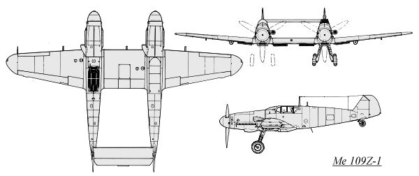