Upon its introduction before the outbreak of the Second World War, the German Me 109 emerged as one of the premier fighter designs globally. While it proved formidable during the conflict, rival aircraft gradually matched and even exceeded its performance in several key areas. In a bid to secure a successor for the Me 109 late in the war, Messerschmitt endeavored to develop the Me 209A, a highly modified design based on its predecessor. Despite demonstrating promising flight attributes, logistical constraints hindered its adoption for active service.
While the Germans acknowledged the effectiveness of the Me 109, it became evident that a new fighter design, or serious enhancements to the existing model, would be necessary. In early 1941, Messerschmitt began developing a successor to the Me 109. This exploration resulted in the creation of the Me 309. It was a brand-new fighter aircraft that incorporated a new fuselage design, larger wings, and a tricycle undercarriage. It was powered by a 1,750 hp DB 603A-1. A few different armament systems were to be tested including four 13 mm MG 131 (300 rounds), two 2 cm MG 151 (150 rounds), and two 30 mm MK 108 (65 rounds) cannons. Alternatively, it could be outfitted with two 15 mm MG 151 cannons and three 13 mm MG 131s.
By June 1942, the prototype underwent flight testing. Despite an initially promising design, testing revealed that the Me 309 did not offer significant improvements over the Me 109G, which was already in mass production. Consequently, recognizing the impracticality of further investment, the Me 309 project was ultimately terminated.
The Me 309 was one of the Messerschmitt failed attempts to develop a successor for the Me 109. Source: www.luftwaffephotos.com
As the development of the Me 309 proved fruitless, Messerschmitt continued to strive towards a suitable replacement for the Me 109. Fortunately for the company, the German Air Ministry (RLM) initiated the development of a new high-altitude fighter on April 23, 1943. In response, Messerschmitt introduced the Me 209. Interestingly, this name was recycled from an earlier project, the original Me 209, which had been crafted specifically to set world-breaking speed records. However, it was ill-suited for military purposes and the project was ultimately shelved having fulfilled its original purpose. Despite this, Messerschmitt endeavored to develop a viable fighter based on the Me 209 but met with little success. To avoid potential confusion, the new project, which bore no resemblance to the record-breaking aircraft, was designated as the Me 209A (also occasionally referred to as the Me 209-II).
The Me 209 which had been crafted specifically to set world-breaking speed records, proved to be unsuited for fighter adaptation. Source: ww2fighters.e-monsite.com
In order to expedite development and minimize costs, the design of this new fighter used many components from the Me 109. A powerful engine was essential for achieving optimal flight performance. Thus, the prototype, powered by a 1,750 PS DB 603A-1 engine, underwent completion and testing in early November 1943, with Fritz Wendel as the pilot. To avoid confusion, it was designated as the Me 209V-5 (SP-LJ), distinguishing it from the original Me 209 prototypes, V-1 to V-4.
The success of the first prototype led to the completion and testing of a second prototype by the end of 1943, both exhibiting impressive flight characteristics. Encouraged by this achievement, construction of another prototype commenced. However, due to shortages of the DB 603A-1 engine, the decision was made to utilize the 1,750 hp Jumo 213E instead. This third prototype underwent flight testing in May 1944, prompting a designation change to Me 209A. The prototypes, with their alternate engine configurations, were then distinguished with the suffixes A-0, A-1, and A-2 for the first, second, and third, respectively.
Technical characteristics
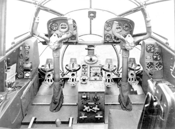
Unfortunately given the obscurity of this project, its overall technical specifications are somewhat ambiguous. What is known is that it incorporated some 65% of its construction from the Me 109G. The original Me 109 fuselage was a monocoque design that was divided into two halves. These halves would be placed together and connected using simple flush rivets, thus creating a simple base on which remaining components, like the engine, wings, and instruments would be installed.
In order to accommodate the retracting landing gear, Messerschmitt deliberately opted for a single wing spar positioned towards the rear of the wing. This spar needed to be robust enough to withstand the flight’s load forces. The wings were attached to the fuselage by four sturdy bolts, simplifying the overall wing construction and reducing production costs. The Me209A boasted a larger wingspan and area, consequently increasing wing loading by 25% compared to the original Me 109. Furthermore, alterations were made to the wings and tail to address the Me 109’s strong yaw forces on takeoff. Whether these adjustments successfully rectified the issue in the Me 209A remains unclear according to available sources.
Initially, it was powered by a 1,750 hp DB 603A-1 engine which was provided with an annular radiator and a three-blade propeller. With this engine, a maximum record speed achieved was 724 km/h 450 mph at an altitude of nearly 7 km (22,960 ft). The third prototype (A-2) received a new 1,750 hp Jumo 213E engine. It too was provided with an annular radiator. With it, a maximum speed of 660 km/h (410 mph) was achieved at an altitude of 6 km (19/680 ft)
The canopy was placed in the center of the fuselage. It was a fully enclosed compartment that was riveted to the fuselage.
The Me 109 boasted an unconventional landing gear arrangement, at least for German standards, with the landing gear primarily affixed to the lower center base of the fuselage. This configuration centralized the aircraft’s weight at this pivotal point, while the two landing gear struts extended outward toward the wings. In contrast, the Me 209 utilized a wide-track undercarriage unit, with the pivot points being out on the wings.
Various sources have proposed different armament configurations for the Me 209. One suggestion was the installation of two 3 cm MK 108 cannons, each equipped with 70 rounds of ammunition, alongside two 2 cm MG 151 cannons with 250 rounds per cannon, all to be housed within the aircraft’s wings. Alternatively, another proposal suggested the placement of four MK 108 cannons within the wings and two MG 151 cannons positioned above the engine compartment. However, it remains unclear whether any of these proposed armament configurations were ever implemented on the Me 209A.
The side view of the only photograph of the Me 209A first prototype. Source: http://www.luftwaffephotos.com/lme2091.htm
Fate
In 1944, further testing ensued, yet for Messerschmitt, the advent of the new Fw 190D posed a challenge. The Fw 190D, slowly making its way into production, boasted better performance, being faster in both high and low altitudes. What ultimately sealed the fate of the Me 209A project was the swiftness and cost-effectiveness with which the Fw 190D could be put into production. While the Me 209 incorporated many components from the Me 109, setting up its production would demand considerable time. A luxury in short supply for the Germans in 1944. Additionally, Messerschmitt’s focus at that time was squarely on the new Me 262 production, leaving scant resources to spare for yet another piston-powered fighter.
Despite these challenges, Messerschmitt made a final push to advance the Me 209 project with the construction and testing of the fourth prototype, designated Me 209H V-1, in June 1944. This iteration underwent several modifications, including enlarged wings and propulsion by a DB 603G engine. Unfortunately, the first prototype fell victim to an air raid on August 14, 1944, casting uncertainty over the fate of the remaining aircraft. Although there were intentions to export the Me 209A to Japan, these plans never materialized. It was also competing with the Ta 152H, which was easier to put into production while also having better performance, at least on paper.
Prototypes
Me 209A-0- First prototype powered by a 1,750 hp DB 603A-1 engine
Me 209A-1- Secon aircraft is essentially a copy of the first prototype
Me 209A-2- Third tested with a new 1,750 Jumo 213E engine
Me 209H V-1 – The fourth prototype powered by a DB 603G engine and received larger wings
Conclusion
The Me 209A project ultimately reached a dead end, not because it was a poorly designed aircraft, but simply because it didn’t offer significant enough improvements to justify production. The new Fw 109D, boasting similar flight performance, was already in the production phase. Introducing yet another new design without any notable advancements in this fighter category would have been illogical and a waste of already meager resources.
Me 209A-2 Specifications
Wingspans
10.95 m / 35 ft 11 in
Length
9.62 m / 31 ft 6 in
Height
3.65 m / 12 ft 2 in
Wing Area
17.15 m² / 184.53 ft²
Engine
1,750 hp Jumo 213E
Empty Weight
3,475kg / 7,662 lbs
Maximum Takeoff Weight
4,200 kg / 9,261 lbs
Maximum Speed
660 km/h / 410 mph
Cruising speed
490 km/h / 305 mph
Range
690 km / 430 miles
Maximum Service Ceiling
13,000 m / 42,650 ft
Crew
1 pilot
Armament
None
Illustration
Credits
Written by Marko P.
Edited by Henry H.
Illustrations by Oussama Mohamed “Godzilla”
Source:
D. Nesić (2008) Naoružanje Drugog Svetsko Rata-Nemačka. Beograd.
D. Monday (2006) The Hamlyn Concise Guide To Axis Aircraft OF World War II, Bounty Books.
J. R. Smith and A. L. Kay (1972) German Aircraft of the WW2, Putnam
D. Myhra (2000) Messerschmitt Me 209V1, Schiffer Military History
B. C.Wheeler, German Fighters of WWII, Aeroplane Special
R. Jackson (2005) Infamous Aircraft, Pen and Sword
M. Griehl () X-planes German Luftwaffe prototypes 1930-1940, Frontline Book
Italy (1932)
Experimental Aircraft – One Prototype Built
In the history of aviation, there have been many projects that on paper promised outstanding flight capabilities, or offered other technical advantages. The time before the Second World War saw aviation advance at a breakneck pace, and is well known for such experiments. The so-called Stipa-Caproni was one such project, being an intriguing, and somewhat bizarre, experimental aircraft designed by Italian aeronautical engineer Luigi Stipa, and built by Caproni during the interwar period. It was characterized by its tubular fuselage, hence earning it the nickname Flying Barrel.
The unique design Stripa-Caproni experimental aircraft. Source: Wiki
History
In 1927 a young Italian aircraft engineer Luigi Stipa began working on an unusual tube-shaped aircraft. Like many other aviation enthusiasts, Stipa was very interested in how aircraft could achieve better performance through exploring unorthodox construction methods. Thanks to his studies in thermodynamics, he was aware of the so-called Venturi effect, named after Italian physicist Giovanni Battista Venturi. In essence, this effect describes the reduction of fluid pressure and increasing velocity when it’s moving through a cylinder of decreased diameter. In theory, using this principle, a special type of aircraft could be created that could achieve significantly higher speeds than the conventional models of the time. Stipa theorized that for this purpose, such an aircraft would have to have a tube-shaped fuselage with the engine being positioned near the front. After finding it theoretically possible, he moved forward to test if the Venturi effect could be implemented in his airplane concept. For this purpose, he began a series of different tests inside a wing tunnel, carried out at the Aerodynamic Laboratory in Rome, from 1928 to 1931. The main focus of this testing period was to find the adequate shape, and leading edges, of the tube-shaped fuselage. This also included finding the right position of the engine, its position inside that tube, and the ideal propeller rotation speed. Following a series of wind tunnel tests, Stipa concluded that it was possible to build a full-scale prototype by using a single tube-shaped fuselage.
Luigi Stipa in his younger years. Source: Wiki
At the end of his research, he concluded that such a project was viable and set the task of building a working prototype. To gain interest in his project, he wrote about his work in the Rivista Aeronautica journal in 1931, and even built a small working replica. The next logical step was to write to the Italian Minister of Aviation, in the hope of getting approval for the realization of his project. Luckily for Stipa, his work came to the attention of General Luigi Crocco, the Air Ministry’s director. Stipa’s work was well received and the project received a green light. To test the concept, a working prototype had to be constructed. It is important to note, that both Stipa and the Italian Air Ministry were aware that this project was merely to test his theories, and would not entail any further development of the prototype. In addition, both were aware that Stipa’s proposed principle was only practical on larger aircraft types.
For this purpose, the prototype was to be powered by a small 120-hp engine. The reason behind this decision lay in the fact that this aircraft was primarily built for evaluation and academic purposes. The Italian Air Ministry was not quite willing to invest huge monetary resources in it, beyond those necessary for the construction of the working prototype.
To help build the test aircraft, the Caproni aircraft manufacturer from Milan Taliedo was chosen. It was designated as Stipa-Caproni (sometimes referred to as Caproni-Stipa) referring to its designer and constructor. The prototype was built quickly and was ready for testing in October 1932.
It is perhaps a little surprising that such an unusual design would receive the necessary support for its realization. However, the exploration of new and unorthodox ideas in aviation was very popular in pre-war Europe. During the 1930s, Italy led the way in this aspect, perhaps even more than other countries, testing many unorthodox designs. What’s more, the Italian Fascist regime even encouraged different and unusual projects like this one, although many of them did not produce any meaningful results.
The Stipa-Caproni prototype was used for testing during 1932 and 1933. Source: en.topwar.ru
Technical specification
The Stipa-Caproni was a two-seater, mixed-construction aircraft, designed to have the simplest and thus cheapest fuselage. Its fuselage consisted of a tube which internally consisted of two large wooden round-shaped rings at the nose, followed by a series of similar but smaller rings. All of them were then connected with horizontal ribs which in turn were covered in fabric. The outer wooden rings served as the foundation, on which the wing and the cockpit would be connected. The fuselage design was, in effect, a large tube shaped airfoil.
A close-up view of the Stipa-Caproni internal fuselage construction. The two larger wooden rings serve as a base to which wings and the cockpit would be attached. Source: www.thevintagenews.com
The wings were mounted centrally on each side of the fuselage. These had a simple wooden construction, and were covered in fabric. They were also connected to the fuselage through metal bracing wires, which as a consequence increased the aircraft’s drag.
To the rear, a fairly large tail assembly was placed. During the design work of this aircraft, Stipa intentionally placed the rear control surfaces as close to the slipstream as possible. He hoped that this arrangement would greatly improve the aircraft’s handling and maneuverability.
On top of the fuselage, an elevated two-seat cockpit was placed. These were top-open with a small windshield placed in front of each position. There were also a pair of small doors that opened on the left side to give access to the seats.
The 120-hp de Havilland Gypsy III engine was placed inside this fuselage. It was centrally positioned and suspended using several steel bars that held it strongly in place. This was necessary to do so, as a weaker mounting could potentially endanger the aircraft during flight. The engine propeller was the almost the same diameter as the tube-shaped fuselage.
Given its overall design, and the position of the propellers inside the fuselage, the landing wheels were small and quite close to the ground. It consisted of three fixed road wheels. Two larger on the front and one smaller on the rear. Initially, wheel fairings were used but at some point, and for unclear reasons, these were removed.
A front view of the unusual engine installation. The engine itself was held in place by several metal bars. Source: WikiIt was provided with a small and fixed three-wheel landing gear. Source: en.topwar.ru
Testing and Final Fate
With this project approved, a prototype was constructed and air tested in October 1932 at the experimental field at Monte Celio near Rome. Despite its odd design, the prototype was able to take to the sky without any major problems. Furthermore, it made several successful flights around Taliedo and Guidnia. It was even presented to the Italian Air Force for future test flights. During this period the aircraft was jokingly nicknamed Flying Barrel or Aereo Botte (Eng. Wooden wine barrel aircraft) or Aereo Barile (Eng. Fuel-Barrel aircraft).
The weight of the aircraft during these flights was 800 kg (1,874 lb), while the calculated wing loading was 44,73 kg/m² (9,16 lb sq.ft.). The maximum speed achieved was 133 km/h (83 mph), and it needed 40 minutes to climb at a height of 3, 000 m. It needed an 800 m long airfield to be able to take to the sky.
The Stipa-Caproni during one of many test flights. Source: www.historynet.com
Despite Stipa’s hopes that the position and shape of the tail control surfaces would improve its mobility, several problems were noted by the test pilots. Firstly the elevator worked very well, which ironically proved to be a major problem. Even with a slight movement of the command control stick by the pilots, the aircraft could prove very sensitive to elevator inputs. On the other hand, the rudder controls were quite stiff, as a consequence the pilot had to use considerable force in order to use it effectively. Analyzing this problem showed that the rudder’s large surface area was to blame for its stiff control. But besides the two problems, the aircraft was reported to be easy to fly when being used in a gliding flight. These defects were of a more or less technical nature, which were not necessarily irremediable through further development of the overall design.
The design of the rear tail assembly proved somewhat problematic. Specifically, the elevator control was overly sensitive while the rudder was quite the opposite. Source: en.topwar.ru
The final results of evaluation flights showed that the Stipa-Caproni does not have any particularly great advantages compared to other more standard aircraft designs. In addition, Stipa-Caproni’s overall aircraft shape offered limited space within the fuselage for passengers or payload.
As Stipa predicted from the start, his principles would not offer any major advantage over a standard smaller-dimension aircraft. The real application of the Stipa-Caproni design was only feasible on larger aircraft. Stipa hoped that his further research would enable him to construct large aircraft powered by two to three tube-shaped engine mounts. Unfortunately for him, after a series of test flights during 1932 and 1933 the interest in his work died out. It was briefly used in various Italian aviation propaganda publications before being scrapped in 1939.
Despite being in general an unimpressive design, the French showed interest in it. Particularly the company ANF Lex Maureaux, which went so far as to acquire a license for the design in 1935. According to initial plans, a two-engine variant was to be built for testing and evaluation. The project did not go beyond basic work was later canceled.
Lastly, an interesting fact is that many people considered Stipa-Caproni to design some sort of proto-jet engine. Whether this was the case or not, Stipa felt his work was overlooked, and according to some sources, he remained bitter throughout his life until he died in the early 1990s.
Stipa hoped that with more resources he would be able to test his principle on a much larger scale, but ultimately nothing came of it. Source: L. Stipa, Stipa Monoplane with Venturi Fuselage
Replica
In 1996, aviation enthusiast Guido Zuccoli began working on a smaller replica of this aircraft. However, the death of Zuccoli in a landing accident caused a delay in the replica’s final delivery. It was finally completed in 2001 when numerous small flights were achieved. The aircraft, powered by a 72 hp Simonini racing engine, managed to achieve a flight distance of 600 m (1,968 ft). After that, the aircraft replica was stored as an exhibit at the Zuccoli Collection at Toowoomba, in Australia.
A smaller-scale replica was built and flight-tested in 2001. Source: www.uasvison.com
Conclusion
The Stipa-Caproni represented an intended for the purpose of testing his new concepts in practice. While surely an interesting and unusual concept, Stipa-Caproni’s overall design was not that practical in reality, offering little improvement over a standard aircraft design of similar dimensions.
Stipa-Caproni Specifications
Wingspans
14.3 m / 46 ft 10 in
Length
6.04 m / 19 ft 10 in
Height
3.2 m / 10 ft 7 in
Wing Area
19 m² / 204 ft²
Engine
One 120 hp (89.5 kW) De Havilland Gipsy III
Empty Weight
595 kg / lbs
Maximum Take-off Weight
850 kg / 1,874 lbs
Maximum Speed
133 km/h / 83 mph
Landing Speed
68 km/h / 42 mph
Climbing speed to 3,000 m
40 min
Maximum Service Ceiling
3,700 m / ft
Crew
1 to 2 pilots
Armament
None
Illustration
Credits
Written by Marko P.
Edited by Henry H. & Ed J.
Illustration by Godzilla
Source:
J. Thompson (1963) Italian Civil and Military Aircraft 1930-1945, Aero Publisher
R. Giacomelli, (1933) The Stipa-Caproni Monoplane, Aircraft Engineering and Aerospace Technology, Vol. 5
D. Nesic (2008) Naoružanje Drugog Svetsko Rata-Italija
L. Salari, Caproni Storia della nascitadell’ industria aeronautica
M Taylor, The Wolrd Strangest Aircraft, Metro Books
O. E. Lancaster (1959) Jet Propulsion Engines, Princeton University Press
L. Stipa (1933) Stipa Monoplane with Venturi Fuselage, Technical Memorandums Nation Advisory Committee For Aeronautics No.753
USSR (1921)
Experimental Single-seat light aircraft – 1 Prototype Built
While the Russian Civil War was raging on, there were early attempts to rebuild its shattered aviation industry. Aviation engineers and enthusiasts attempted, despite the chaos around them, to build small experimental aircraft to test their ideas and concepts. One such young individual was Andrei Nikolayevich Tupolev. His ANT-1 was a specialized design to test the concept of using metal alloys in aircraft construction.
Tupolev began his career as an aircraft engineer in 1909, when he was admitted to the Moscow Higher Technical School. There he met Professor Nikolai Yagorovich who greatly influenced Tupolev’s interest in aviation. In the following years, he spent time developing and testing various glider designs. When the First World War broke out Tupolev managed to get a job at the Russian Dux Automotive factory in Moscow, which produced a variety of goods, including aircraft. There he gained valuable experience of aircraft manufacturing.
Andrei Nikolayevich Tupolev was one of the greatest Russian/Soviet aviation engineers and designers. Source: Wiki
In 1917, the October Revolution plunged the disintegrating Russian Empire into total chaos. The few aircraft manufacturing centers were either abandoned or destroyed. All work on the design and construction of new aircraft was essentially stopped. The Dux was one exception and continued to work at a limited capacity. It was renamed to Gosudarstvennyi aviatsionnyi zavod (Eng. State aircraft factory) or simply GAZ No.1. Given that he was one of few aviation engineers left, with most skilled either being killed or fled the country, Tupolev remained working for the GAZ No.1. He spent a few years working on various projects such as designs improving weapon mounts for older aircraft that were still in service.
In 1921, Tupolev was elected as the deputy of the Aviatsii i Gidrodinamiki AGO (Eng. Aviation and Hydrodynamics Department). This department was tasked with developing various aircraft designs but also including torpedo boats. In 1921 he and his team from AGO began working on a new aircraft design that was to test new concepts. Two new innovative features were that it should be a monoplane, and be built using mainly metal alloy. Its primary purpose was not to gain any production orders, but instead to serve as a test bed for new ideas and concepts. The aircraft was named ANT-1, where ANT stands for the initials of Andrei Nikolayevich Tupovlev. This designation should not be confused with a snowmobile developed by Tupolev, which shared its name.
During this period, Soviet aviation officials and the German Junkers company spent years negotiating the possibility of producing a Duralumin alloy that could be used for aviation construction. Junkers proved the validity of this concept on the J.I saw service during the First World War. The German company wanted to avoid sanctions on arms and aviation development imposed by the Allies, while the Soviets wanted the technology for themselves, not wanting to depend on the Germans entirely. The Soviet Union in 1922, managed to produce their own copy of Duralumin known as Kol’schugaluminiyem alloy. The name was related to a small village Kol’chugino where this factory was located. Limited production of this alloy began in 1923.
Due to problems with the production of the new alloy, Tupolev was forced to postpone the development of his new aircraft until 1922. At that time the alloy was not yet available, so Tupovlev decided to go on with a mix-construction design, but mostly using wood. The benefit of using wood was that it was an easily available material, with almost unlimited supply in Russia. It was cheap and there were plenty of skilled woodworkers. However, there were also numerous flaws in using wooden materials. The greatest issue was a generally short service life in harsh climates as in Russia, in addition, standardization of spare parts is almost impossible to do.
Tupolev himself preferred the new metal technology believing that it would offer many benefits to the aircraft industry, giving new aircraft a lighter and stronger overall construction. Tupolev eventually decided to go for a mixed-construction solution. His decision was based on a few factors, such as the general lack of this new material, and he wanted to be on the safe side as using metal in aircraft construction was still a new and not yet fully proven concept. In addition, he wanted to be sure about the Aluminum alloy material’s quality before proceeding to design a fully metal aircraft.
Once the choice for the construction material was solved the next step was to decide whether it was to be a single or two-seat configuration. The wing design was also greatly considered. After some time spent in calculations and small wind testing, the choice was made to proceed with a single engine and low-wing monoplane.
For the engine, three different types were proposed including 14hp and 18 hp Harley-Davidson and a 20 hp Blackburn Tomtit. Despite Tupovlev’s attempts, he failed to acquire any one of these three. It was not until early 1923 that he managed to get his hands on an old 35hp Anzani engine which was over 10 years old by that point. Despite its poor mechanical state, Tupovlev knowing that nothing else was available decided to try salvage it.
Testing and the Final Fate
The construction of this aircraft took over a year to complete. Given the general chaos at that time, this should not be surprising. It was finally completed in October 1923, and the first test flight was carried out on the 21st of October of the same year. Despite using the older engine, the flight proved successful. It was piloted by Yevgeni Pogosski.
The completed ANT-1 test aircraft. Source: www.globalsecurity.org
Following this, the ANT-1 was used mainly for various testing and evaluation. It would see service in this manner for the next two years. In 1925 the aging engine finally gave up, and this made the aircraft unflyable. Tupovlev tried to find a factory that could potentially refurbish it. He ultimately failed, as the engine was simply beyond repair by that point.
The aircraft was for some time stored at Factory No.156. The fate of this aircraft is not clear in the sources, however, there are few theories about what happened to it. After Tupovlev’s imprisonment by Josef Stalin, his plans and documentation were confiscated. The aircraft was believed to be also confiscated and scrapped in the late 1930s. Another possibility is that it was moved to another storage facility where it was eventually lost during the Axis Invasion of the Soviet Union in 1941.
Specification
The ANT-1 was designed as a cantilever low-wing monoplane aircraft of mixed construction. The fuselage consisted of four spruce longerons. The lower two were connected to the wing spars and were held in place with four bolts. The parts of the fuselage starting with the pilot cockpit to the engine were covered in the metal alloy. This alloy was also used to provide additional strength of some internal wooden components of the aircraft fuselage. The pilot Pilot cockpit was provided with a small windscreen. Inboard equipment was spartan consisting only of an rpm counter, oil pressure indicator, and ignition switch.
The cantilever wings were made of single pieces. At the end of the two tips (on each side of the wings) large wooden spars were installed. Some parts of the wing were built using metal parts such as the wing ribs, The rest of the wing was mainly covered in fabric. The tail unit was made of wood, its surfaces were covered with a metal-fabric cover.
The fixed landing gear consisted of two large wheels. These were connected to a metal frame which itself was connected to the aircraft fuselage. Small rubber bungees acted as primitive shock absorbers.
Given that nothing else was available, the ANT-1 was powered by an old, refurbished 35-hp strong Bristol Anzani engine.
A good view of the ANT-1 internal wing and fuselage construction. Source: www.globalsecurity.orgThe cantilever wings received on each side one large wooden spar. Source: WikiThe pilot cockpit received only a few basic instruments and a small windshield. Source:www.globalsecurity.org
Conclusion
The ANT-1 despite its simplicity, and being built a single, cobbled-together prototype, could be considered a great success for Tupolev. Through this experimental aircraft, Tupovlev gained valuable experience in designing an aircraft by using metal alloy. This success emboldened Tupovlev to go even further and design and build the Soviet first all-metal construction aircraft known as ANT-2. The ANT-1 was Tupovlev’s first stepping stone in a long and successful career as an aircraft designer in the following decades.
ANT-1 Specifications
Wingspans
7.2 m / 23ft 7 in
Length
5.4 m / 17 ft 8 in
Height
1.7 m / 5 ft 7 in
Wing Area
10 m² / 108 ft²
Engine
One 35 hp Bristol Anzani engine
Empty Weight
230 kg / 5,070 lb
Maximum Takeoff Weight
360 kg / 7,940 lb
Maximum Speed
125 km/h / 78 mp/h
Range
400 km / 250 miles
Maximum Service Ceiling
600 m / 1,970 ft
Maximum Theoretical Service Ceiling
4,000 m / 13,120 ft
Crew
1 pilot
Armament
None
Gallery
Credits
Article written by Marko P.
Edited by Henry H.
Illustration by Godzilla
Sources:
Duško N. (2008) Naoružanje Drugog Svetsko Rata-SSSR. Beograd.
Y. Gordon and V. Rigmant (2005) OKB Tupolev, Midland
P. Duffy and A. Kandalov (1996) Tupolev The Man and His Aircraft, SAE International
B. Gunston () Tupolev Aircraft Since 1922, Naval Institute press
In the later stages of the Second World War, it was becoming apparent to both the Luftwaffe (English German Air Force) and the German Government that the Allied air forces were gaining air superiority. This realization saw them turn to new and fantastical ideas in a desperate attempt to turn the tide of the war. Some of these represented new improvements to existing designs, the introduction of the newly developed turbojet engine, and even more esoteric and experimental methods. In many cases, these were pure fantasies, unrealistic or desperate designs with no hope of success. Few of them reached any significant development, and among them were the works of Alexander Martin Lippisch. While Lippisch helped develop the Me 163, the first rocket-powered interceptor, his other work remained mostly theoretical. One such project was the unusual P 13a, ramjet-powered aircraft that was to use coal as its main fuel source. While some work was carried out late in the war and soon faced insurmountable technical problems, thus nothing came of the project.
Artistic presentation of how the P 13a may have looked. Source: Luftwaffe Secret Jets of the Third Reich
History
Before the start of the Second World War, aviation enthusiast and engineer Alexander Martin Lippisch, was fascinated with tailless delta wing designs. Lippisch’s early work primarily involved the development of experimental gliders. Eventually, he made a breakthrough at the Deutsche Forschungsinstitut, where he worked as an engineer. His work at DFS would lead to the creation of the rocket-powered glider known as the DFS 194. As this design was a promising experiment in a new field, it was moved to Messerschmitt’s facility at Augsburg. After some time spent refining this design, it eventually led to the development of the Me 163 rocket-powered interceptor. While it was a relatively cheap aircraft, it could never be mass-produced, mostly due to difficulties associated with its highly volatile fuel. In 1942, Lippisch left Messerschmitt and ceased work on the Me 163 project. Instead, he joined the Luftfahrtforschungsanstalt Wien (English: Aeronautic Research Institute in Vienna) where he continued working on his delta-wing aircraft designs. In May 1943 he became director of this institution, and at that time the work on a supersonic aircraft was initiated.
In the later war years, among the many issues facing the Luftwaffe, was a chronic fuel shortage. Lippisch and his team wanted to overcome this problem by introducing alternative fuels for their aircraft. Luckily for his team, DFS was testing a new ramjet engine. They were designed to compress air which would be mixed with fuel to create thrust but without a mechanical compressor. While this is, at least in theory, much simpler to build than a standard jet engine, it can not function during take-off as it requires a high airflow through it to function. Thus, an auxiliary power plant was needed. It should, however, be noted that this was not new technology and had existed since 1913, when a French engineer by the name of Rene Lorin patented such an engine. Due to a lack of necessary materials, it was not possible to build a fully operational prototype at that time, and it would take decades before a proper ramjet could be completed. In Germany, work on such engines was mostly carried out by Hellmuth Walter during the 1930s. While his initial work was promising, he eventually gave up on its development and switched to a rocket engine instead. The first working prototype was built and tested by the German Research Center for Gliding in 1942. It was later tested by mounting the engine on a Dornier Do 17 and, later, a Dornier Do 217.
The Dornier Do 217 was equipped with experimental ramjets during trials. Source: tanks45.tripod.com
In October 1943, Lippisch won a contract to develop the experimental P 11 delta-wing aircraft. While developing this aircraft, Lippisch became interested in merging his new work with a ramjet engine. This would lead to the creation of a new project named the P 12. In the early stage of the project, Lippisch and his team were not completely sure what to use as fuel for their aircraft, but ramjets could be adapted to use other types of fuel beyond aviation gasoline.
Unfortunately for them, LFW’s facilities were heavily damaged in the Allied bombing raids in June 1944. In addition to the damage to the project itself, over 45 team members died during this raid. To further complicate matters, the scarcity of gasoline meant that Lippisch’s team was forced to seek other available resources, such as different forms of coal. This led to the creation of the slightly modified project named P 13. In contrast to the P 12, the cockpit was relocated from the fuselage into a large fin. This design provided better stability but also increased the aircraft’s aerodynamic properties. The overall designs of the P 12 and P 13 would change several times and were never fully finalized.
The P 12 and 13 small-scale models, in both configurations, were successfully tested at Spitzerberg Airfield near Vienna in May 1944. The project even received a green light from the Ministry of Armaments. In the early stages of the project, there were some concerns that the radical new design would require extensive retraining of pilots. However, the wind tunnel test showed that the design was aerodynamically feasible and that the aircraft controls had no major issues. Based on these tests, work on an experimental aircraft was ordered to begin as soon as possible.
A proposed P 12 aircraft. Its designs changed greatly over time, before being finally discarded in favor of the letter P 13. Source: The Delta Wing History and Development
The DM-1 Life Saver
While working on the P 12 and P 13, Lippish was approached with a request from a group of students from Darmstadt and Munich universities. They asked Lippisch to be somehow involved in the P 12 and 13 projects. Lippisch agreed to this and dispatched one of his assistants under the excuse that for his own project, a wooden glider was to be built and tested. The previously mentioned student’s and Lippisch’s assistant moved to a small warehouse in Prier and began working on the Darmstadt 33 (D 33) project. The name would be changed to DM 1 which stands for Darmstadt and Munich.
At this point of the war, all available manpower was recruited to serve the German war effort. For young people, this often meant mobilization into the Army. One way to avoid this was to be involved in some miracle project that offered the Army a potentially war-winning weapon. It is from this, that numerous aircraft designs with futuristic, and in most cases unrealistic, features were proposed. Many young engineers would go on to avoid military service by proposing projects that on paper offered extraordinary performance in combat.
The students and Lippisch managed to nearly complete their DM1 test glider when the war ended. Source: airandspace.si.edu
While it was under construction, preparations were made to prepare for its first test flight. As it was a glider it needed a towing aircraft that was to take it to the sky. A Sibel Si 204 twin-engine aircraft was chosen for the job. However, this was not to be done like any other glider, being towed behind the larger aircraft. Instead, the DM-1 was to be placed above the Si 201 in a frame, in a similar combination as the Mistel project. The estimated theoretical speeds that were to be reached were 560 km/h (350 mph).
Allegedly, there were four different proposals for the DM’s that were to be fully operational. The DM 2 version was estimated to be able to reach a speed of 800-1,200 km/h (500 – 745 mph). The DM 3’s theoretical maximum speed was to be 2,000 km/h (1,240 mph) while the fate of the DM 4 is unknown. Here it is important to note that these figures were purely theoretical, as there were no supersonic testing facilities to trial such a design. It is unclear in the sources if these additional DM projects even existed, even if in only written form. We must remember that the whole DM 1 glider idea was made to help the students avoid military conscription and that Lippisch himself never saw the DM 1 as any vital part of the P 13.
In any case, the glider was almost completed by the time the war ended and was later captured by the Western Allies. Under the US Army’s supervision, the glider was fully completed and sent to America for future evaluation. It would then be given to the Smithsonian Institution.
A DM 1 test glider being under construction. Source: hushkit.netThe Siebel Si 204 was to be used as a carrier for the DM 1 glider for the expected first-flight tests. Due to the end of the war, this was never achieved. Source: www.silverhawkauthor.com
Work on the P 13
As the work on the P 13 went on, the name was slightly changed. This was necessary as different variations of the P 13 were proposed. The original P 13 received the prefix ‘a’ while the later project’s designation continued alphabetically for example P 13b. After a brief period of examination of the best options, the P 12 project was discarded in favor of P 13. The decision was based on the fuel that the aircraft should use. What followed was a period of testing and evaluation of the most suitable forms of coal that could be used as fuel. Initial laboratory test runs were made using solid brown Bohemian coal in combination with oxygen to increase the burn rate. The fuel coal was tube-shaped, with an estimated weight of 1 kg, and encased in a mesh container through which the granulated coal could be ejected. The testing showed serious problems with this concept. While a fuel tube could provide a thrust that on average lasted 4 to 5 minutes, its output was totally unpredictable. During the testing, it was noted that due to the mineral inconsistency of the coal fuel, it was impossible to achieve even burning. Additionally, larger pieces of the coal fuel would be torn off and ejected into the jet stream. The final results of these tests are unknown but seem to have led nowhere, with the concept being abandoned. Given that Germany in the last few months of the war was in complete chaos, not much could be done regarding the Lippish projects including the P 13a.
As more alterations to the original design were proposed its name was charged to P 13a. Here is a drawing of a P 13b that was briefly considered but quickly discarded. Source: The Delta Wing History and Development
In May 1945, Lippish and his team had to flee toward the West to avoid being captured by the advancing Soviets. They went to Strobl in Western Austria, where they encountered the Western Allies. Lippisch was later transported to Paris in late May 1945 to be questioned about his delta wing designs. He was then moved to England, and then to America in 1946. The following year, American engineers tested the DM 1 glider at the wind tunnel facility of the Langley Field Aeronautical Laboratory. The test seems promising and it was suggested to begin preparation for a real flight. A redesign of the large rudder was requested. It was to be replaced with a much smaller one, where the cockpit would be separated from the fin and placed in the fuselage. Ironically Lippish was not mentioned in this report, as technically speaking he was not involved in the DM 1 project. Nevertheless, he was invited for further testing and evaluation of this glider. If this glider and the Lippish work had any real impact on the US designs is not quite clear.
Despite no aircraft being ever completed, one full-size replica of this unusual aircraft was built after the war. It was built by Holger Bull who is known for building other such aircraft. The replica can now be seen at the American Military Aviation Museum located in Virginia Beach.
An interesting full-size replica of the P 13 located at the American Military Aviation Museum. Source: Wiki
Technical characteristics
DM 1
The DM 1 glider was built using wooden materials. Given that it was constructed by a group of young students, its overall design was quite simple. It did not have a traditional fuselage, instead, its base consisted of a delta wing. On top, a large fin was placed. The cockpit was positioned in front of the aircraft within the large vertical stabilizer. To provide a better view of the lower parts of the nose, it was glazed. The landing gear consisted of three small landing wheels which retracted up into the wing fuselage. Given that it was to be used as a test glider, no operational engine was ever to be used on it.
The DM 1 side view. In contrast to the later P 13a design, the pilot’s cockpit position was placed above the wings. This was necessary as the engine was to be added. Source: airandspace.si.eduA DM 1 was captured by the Allies after the war. Its unique shape is quite evident in this photograph. Source: WikiA good example of DM 1 (to the right) and P 13a models that showed the difference between these two. The P 13a could be easily distinguished by its engine intake and the different position of the pilot cockpit. Source: Wiki
A good example of DM 1 (to the right) and P 13a models that showed the difference between these two. The P 13a could be easily distinguished by its engine intake and the different position of the pilot cockpit. Source: Wiki https://imgur.com/a/QW7XuO5
P 13a
The P 13 is visually similar but with some differences. The most obvious was the use of a ramjet. This means that the front, with its glazed nose, was replaced with an engine intake. Here, it is important to note, that much of the P 13a’s design is generally unknown, and much of the available information is sometimes wrongly portrayed in the sources. The P 13a never reached the prototype stage where an aircraft was fully completed. Even as the war ended, much of the aircraft’s design was still theoretical. Thus all the mentioned information and photographs may not fully represent how the P 13 may have looked or its precise characteristics, should it have been finished and built.
The exact ram engine type was never specified. It was positioned in the central fuselage with the air intake to the front and the exhaust to the back. As the main fuel, it was chosen to use small pieces of brown coal which were carried inside a cylindrical wire mesh container. The total fuel load was to be around 800 kg (1,760 lbs). Combustion was to be initiated by using small quintiles of liquid fuel or gas flames. The overall engine design was changed several times during the work on the P 13 without any real solution to the issues of output consistency. Given that the ramjets could not work without an air thrust, an auxiliary engine had to be used during take-off, though a more practical use would be to tow the P 13 until it could start its engine. A rocket takeoff ran the risk of the engine failing to ignite, leaving the pilot little time to search for a landing spot for his unpowered aircraft.
An illustration of the proposed P 13a engine interior. The use of coal as fuel may seem like a cheap alternative but given that this kind of technology was never employed may be an indication of its effectiveness. Source: theaviationgeekclub.com
The wing construction was to be quite robust and provided with deflectors that would prevent any potential damage to the rudders. The wing design also incorporated a sharp metal plate similar to those used for cutting enemy balloons cables. These proposed properties of the wings are another indicator that the P 13 was to be used as an aircraft rammer. Another plausible reason for this design was the fact that given it had no landing gear the aircraft design had to be robust enough as not to be torn apart during landing. The wings were swept back at an angle of 60 degrees. The precise construction method of the wings (and the whole P 13 a on that matter) are not much specified in the sources. Given the scarcity of resources in late 1944 it is likely that it would use a combination of metal and wood.
A drawing of the P 13a interior. Its overall construction was to be more or less standard in nature. This could not be said for the aircraft’s overall shape design. Source: D. Sharp Luftwaffe Secret Jets of the Third Reich
The fin had to be enlarged to provide good flight command characteristics. In addition, given that the position of the cockpit was in the fin, it had to be large. The fin was more or less a direct copy of one of the wings. So it is assumed that it too would share the overall design. The fin was connected to the aircraft by using four fittings.
The cockpit design was to be simple and cheap to build. The pilot was to have plenty of room inside the large fin. The cockpit was provided with a large glazed canopy that provided a good view of the front and sides. The seat and the instrument panel were bolted to the cockpit floor and walls. These could be easily detached for repairs. The instrument panel was to include an artificial horizon indicator, altimeter, compass, and radio equipment, Given that it was to operate at a high altitude oxygen tanks were to be provided too. Despite being intended to fly at high altitudes the cockpit was not to be pressurized. Another unusual fact was that initially the P 13 was to have a crew of two, but this was quickly discarded.
A possible example of how the inside of the pilot cockpit may have looked. Source: D. Sharp Luftwaffe Secret Jets of the Third Reich
Here it is important to note that the version of the P 13 with the large fin is often portrayed as the final version of this aircraft. However, Lippisch never fully decided whether he should go for this version or the second that used a smaller fin with the pilot cockpit placed above the engine intake. Depending on the proposed version they are drastically different from each other. Lippisch, for unknown reasons, presented the British intelligence officer with the version that used the smaller fin and the American with the second version.
During its development phase, many different alterations of the P 13 were proposed. Isource: D. Sharp Luftwaffe Secret Jets of the Third Reich
Landing operations were a bit unusual. To save weight no standard landing gear was to be used. Instead, Lippisch reused the Me 163 landing procedure. As the P 13 was immobile on its own, a small dolly would be used to move the aircraft. Once sufficient height was reached the dolly was to be jettisoned. In theory, this was an easy process, but in practice, this operation offered a good chance of failure and was much less safe than conventional landing gear. Sometimes the dolly either failed to eject or it bounced off the ground hitting the Me 163 in the process, with often fatal consequences.
The Me 163 which did not have traditional landing gear, had to be prior to the flight, transported to the airfield before launching into the sky. Source: warbirdphotographs.com
The aircraft was to land with the nose raised up from the ground. This limited the pilot’s view of the ground. In addition due to its small size and in order to save weight, nontraditional landing gear was provided, instead, it carried a landing blade skid. To help absorb the landing impact, additional torsion springs were to be used. This bar had to be activated prior to the landing, it would emerge from beneath the aircraft fuselage, with the rotation point located at the front. Once released it was to guide the aircraft toward the ground. After that, the torsion springs were to soften the landing. This whole contraption seems like a disaster just waiting to happen and it’s questionable how practical it would be.
A drawing that showed how the P 13a was to land using a guiding landing blade skid. Source: D. Sharp Luftwaffe Secret Jets of the Third Reich
One interesting feature of the P 13 was that it could be easily disassembled into smaller parts which would enable effortless transport. Another reason was that due to the engine’s position in order to make some repairs or replacement of the engine, the remaining parts of the wing and the large fin had to be removed.
Was it an aircraft rammer?
The precise purpose of the P 13a is not quite clear, even to this day. Despite being briefly considered for mass production, no official offensive armament is mentioned in the sources. So how would the P 13a engage the enemy? A possible solution was that it would be used as a ram aircraft that was supposed to hit enemy aircraft damaging them in the process. In an after-the-war interrogation by British officers, Lippisch was asked if the P 13 was to be used as an aerial ram aircraft. Lippisch responded the following “
“.. The possibilities of using the P.13 as a ramming aircraft had been considered but Dr Lippisch did not think that athodyd propulsion was very suitable for this purpose owing to the risk of pieces of the rammed aircraft entering the intake. This would be avoided with a rocket-propelled rammer…”
This statement contradicts the building description issued by the LFW issued in late 1944. In it was stated the following about this potential use. “…Due to tactical considerations, among other things, the speed difference of fighters and bombers, preferably when attacking from behind, though the thought was given to the installation of brakes .. and although ample room for weaponry is present, the task of ram fighter has been taken into account – so that the ramming attack will not lead to the loss of the aircraft, thanks to its shape and static structure.”
This meant that this concept may have been considered by Lippisch at some point of the project’s development. The P 13 overall shape resembles closely to aircraft that was intentionally designed for this role. That said, it does not necessarily mean that the P 13 was to ram enemy aircraft. The use of such tactics was considered but their use was discarded, as it was seen as a futile and flawed concept. The project itself never got far enough to have an armament decided for it.
The precise method of how to engage the enemy aircraft is not clear as the P13a was not provided with any armament. It is sometimes referred to in the sources as it was to be used as a ram aircraft. Source: theaviationgeekclub.com
Conclusion
The Lippisch P 13 is an unusual aircraft project in nearly all aspects. Starting from its shape, which proved, at least during wind tunnel tests, that the concept was feasible. On the other hand, its engine seems to have simply been abandoned after discouraging test results. It is unlikely that such a combination would have worked to the extent that the P 13 designer hoped it would. During the testing, they could not find a proper solution to providing a constant thrust with sufficient force to reach a speed that was expected of it. So the whole concept was likely to be doomed from the start.
The DM 1 however, while it was never seriously worked on by Lippisch himself, managed to save a group of young students who used the project to avoid being sent into combat.
DM-1 Specifications
Wingspans
5.92 m / 19 ft 5 in
Length
6.6 m / 21 ft 7 in
Height
3.18 m / 10 ft 5 in
Wing Area
20 m² / 215 ft²
Engine
None
Empty Weight
300 kg / 655 lbs
Maximum Takeoff Weight
460 kg / 1,015 lbs
Maximum Speed
560 km/h / 350 mph (gliding)
Landing speed
72 km/h / 45 mph
Release altitude
8,000 m (26,240 ft)
Crew
1 pilot
Armament
None
Theoretical Estimated Lippisch P 13 Specifications
Wingspans
5.92 m / 19 ft 5 in
Length
6.7 m / 21 ft 11 in
Height
3.18 m / 10 ft 5 in
Wing Area
20 m² / 215 ft²
Engine
Unspecified ramjet
Maximum Takeoff Weight
2,300 kg / 5,070 lbs
Maximum Speed
1,650 km/h / 1,025 mph
Flight endurance
45 minutes
Fuel load
800 kg / 1,760 lb
Crew
1 pilot
Armament
None mentioned
Illustrations
The Lippisch DM-1, unnecessary to the overall project, it none the less allowed a group of students to escape military service.
A possible silhouette of the P13.
Credits
Article written by Marko P.
Edited by Henry H.
Ported by Marko P.
Illustrated By Medicman11
Source:
A. Lippisch (1981) The Delta Wing History and Development, Iowa State University Press
D. Nesić (2008) Naoružanje Drugog Svetsko Rata-Nemačka. Beograd.
D. Monday (2006) The Hamlyn Concise Guide To Axis Aircraft OF World War II, Bounty Books.
J. R. Smith and A. L. Kay (1972) German Aircraft of the WW2, Putham
B. Rose (2010) Secret Projects Flying Wings and Tailless Aircraft, Midland
D. Sharp (2015) Luftwaffe Secret Jets of the Third Reich, Mortons
Kingdom of Hungary (1939)
Fighter Aircraft – One prototype
In their search for a new fighter, the Magyar Királyi Honvéd Légierő MKHL (English: Royal Hungarian Home Defence Air Force), approached the Germans for help. Initially, a deal was made with the German Heinkel company for the delivery of new He 112 fighters and a production license. However, nothing came of this deal, which led to the Hungarians attempting to develop their own fighter, partially based on the He 112.
In the late 1930s, the Hungarian Air Force was slowly in the process of rebuilding its combat strength by the acquisition of new aircraft. For a modern air force, they needed better fighter designs, which they were then seriously lacking. Luckily for them, they began to improve their relations with Germany, so it was possible to acquire new equipment from them. In June 1938, a Hungarian delegation was sent to the Heinkel company, and the pilots that accompanied this delegation had a chance to fly the He 112 fighter. This aircraft was Heinkel’s response to the Reichsluftfahrtministerium’s (English: German Ministry of Aviation) request for a new fighter. While generally a good design, it ultimately lost to Messerschmitt Bf 109. While the He 112 project was canceled by the RLM, to compensate for the huge investment in resources and time to it, Heinkel was permitted to export this aircraft to foreign buyers. Several countries such as Austria, Japan, Romania, and Finland showed interest, but only a few actually managed to procure this aircraft, and even then, only in limited numbers.
He 112 the unsuccessful competitor of the Bf 109. Source: www.luftwaffephotos.com
The Hungarians were impressed with the He 112 and placed an order for 36 such aircraft. For a number of logistical and political reasons, the decision to sell these aircraft to Hungary was delayed. A single He 112 was given to Hungary in February for evaluation but was lost on its first flight. Realizing that the Germans would not deliver the promised aircraft, the Hungarians instead decided to ask for a license. This was granted and Heinkel also delivered two more He 112 B-1s. When the license arrived in Hungary in May 1939, a production order for the 12 first aircraft was given to Weiss Manfréd aircraft manufacturer.
The first He 112 to reach Hungary, it was lost in an accident during its maiden test flight. Source: D. Bernard Heinkel He 112 in Action
A New Fighter
Despite the best Hungarian attempts to put the He 112 in production, this was prevented by the war between Poland and Germany. At the start of the Second World War, RLM officially prohibited the export of any German aircraft engines and equipment. This meant that the vital Jumo 210 and DB 601 engines would not be available. Based on this fact, all work on the Hungarian He 112 had to be canceled.
The Hungarian Air Force only operated a few He 112, which saw limited service before being reused as training aircraft. Source: www.destinationsjourney.com
As the Hungarians had the license for the He 112, some parts could still be domestically produced. In essence, this offered the Hungarians the chance to develop a new fighter, based on the He 112 blueprints. Not wanting to waste this opportunity, the Hungarian Ministry of War Affairs issued a directive to commence developing a new domestic fighter by reusing some components from the He 112. The whole project was undertaken by WM’s own chief designer Bela Samu, who began development in early 1939. To speed up development, the He 112 wing design was copied, but given the comparatively underdeveloped Hungarian aircraft industry, the wing was to be built of wooden materials instead of metal, as it was on the He 112. Other differences included using an oval-section fuselage, different armament, a new engine, and a cockpit redesign.
The first prototype was completed quickly by the end of 1939. In its prototype stage, the aircraft was painted in a light gray livery, earning it the nickname Ezüst Nyíl (English: Silver arrow) from the personnel that worked on it. Once it was issued to the Air Force for testing, it received the standard Hungarian camouflage scheme, and the designation V/501 was also allocated to it. The maiden test flight was undertaken close to Budapest on the 23rd of February 1940. The flight proved successful and a maximum speed of 530 km/h (330 mph) at a height of 5 km (16.400 ft) was achieved. Some issues were detected, the most problematic proved to be the strong vibration caused by the exhaust system. Despite this, the project development pressed on.
The WM 23, possibly at an early stage of development. It was powered by a 1,030 hp WM K-14B engine which gave it comparable power to the He 112. Source: www.destinationsjourney.com
Short Service Life
Despite the time and effort put into the project, it all went for nothing as the prototype was lost in an accident in February, or April, depending on the source, 1942. During a test flight at high speeds, one of the ailerons simply broke off. The pilot lost control of the aircraft and had to bail out. The uncontrolled plane hit the ground and was utterly destroyed, and with it, the whole project was canceled.
Beyond this major setback, another reason why this project was canceled was the start of the license production of the German Bf 109G fighter. It was much easier, and faster, to commence production of this aircraft, thanks to German technical support, than to completely develop new tooling and equipment for the WM 23.
Technical Characteristics
The WM 23 was a mixed-construction single-engine fighter heavily inspired by the German He 112. Given its somewhat obscure nature, not much is mentioned in the sources about its overall construction. Given the urgency of the project, instead of the monocoque fuselage, the Hungarian engineers decided to use a simpler oval-section fuselage which consisted of welded steel tubes and then covered with plywood. The wings, as mentioned, were taken from the He 112, but had one huge difference, being made of wood, including its control surfaces.
The landing gear was another part more or less taken directly from the He 112. They consisted of two larger landing wheels that retracted into the wings, and one semi-retractable tail wheel. But based on the photographic evidence, their overall design changed during the prototype’s development. On the prototype, possibly at an early stage, a V-shaped front landing gear strut was used. This was later replaced by a large single-leg landing gear. The cockpit was equipped with a sliding canopy that slid to the rear.
The WM 23 was powered by a 1,030 hp WM K-14B (sometimes marked as 14/B) engine. This engine was developed based on the license of the French Gnome and Rhone 14K engine, a fourteen-cylinder radial engine equipped with a single-stage, single-speed supercharger. As mentioned, during the fifth test maximum achieved speed was 530 km/h (330 mph).
While the prototype was never fitted with an offensive armament, the Hungarians had plans for a potential armament In the wing, two 8 mm (0.33 in) machine guns were to be installed. In addition, two 12.7 mm (0.5 in) heavy machine guns were to be added atop the engine compartment. Lastly it was to have a payload of two 20 kg bombs (44 lbs).
There are very few surviving photographs of the WM 23. While showing promising performance, the destruction of the only prototype and the commencement of the Bf 109G’s production in Hungary ultimately lead to the cancelation of this project. Source: D. Bernard Heinkel He 112 in Action
Conclusion
The WM 23 was an interesting Hungarian attempt to domestically develop and build a fighter aircraft that was greatly influenced by the He 112. It showed to be a promising design, with the prospect of entering serial production. However, the loss of the single prototype put an end to this project. By 1942, the Hungarians simply did not have the time to start over again with the WM 23, so they abandoned it in favor of the license production of the German Bf 109G.
WM 23 prototype Specifications
Wingspans
31 ft 5 in / 9.6 m
Length
29 ft 10 in / 9.1 m
Height
10 ft 9 in / 3.3 m
Wing Area
199 ft² / 18.5 m²
Engine
One 1,030 hp strong WM K-14B
Empty Weight
4,850 lbs / 2,200 kg
Maximum Take-off Weight
5,733 lbs / 2,600 kg
Maximum Speed
330 mph / 530 km/h
Crew
1 pilot
Proposed Armament
Two 12.7 mm (0.5 in) heavy machine guns and two machine guns 8 mm (0.33 in) machine guns plus a bomb load of 20 kg (44 lbs)
Credits
Article written by Marko P.
Edited by Henry H.
Ported by Marko P.
Illustrated By Carpaticus
Illustrations
The WM-23’s factory test colorsWM-23 with Hungarian Airforce livery
Source:
D. Monday (2006) The Hamlyn Concise Guide To Axis Aircraft OF World War II, Bounty Books
D. Bernard (1996) Heinkel He 112 in Action, Signal Publication
G. Punka, Hungarian Air Force, Signal Publication
R.S. Hirsch, U, Feist and H. J. Nowarra (1967) Heinkel 100, 112, Aero Publisher
C. Chants (2007) Aircraft of World War II, Grange Books
J. R. Smith and A. L. Kay (1990) German Aircraft of the Second World War, Putnam
Side view of the Boulton Paul P.105C. This was the single-seat fighter version of the aircraft, armed with four 20mm cannons. (Boulton Paul Archive Photos)
The Boulton Paul P.105 was a concept for a multi-purpose, single-engine aircraft that was designed to fill a number of carrier based roles. To do so, the P.105 would utilize a unique and innovative method that would use interchangeable fuselage sections and cockpit modules that would allow the aircraft to perform different missions. These modules could be changed quickly to fill a needed role aboard carriers or airbases. The aircraft would not be chosen for production, and The P.105 would be developed further into the P.107, a land-based escort version. The P.107 would have a rear-facing turret and a twin boom tail design to allow greater traverse of the gun. This design wouldn’t be adopted either, and the program would conclude before the war’s end.
History
Late in the Second World War, the Royal Naval Air Arm began seeking out a new aircraft design that would be able to fill both the fighter and bomber roles aboard their carriers. Having one aircraft perform multiple roles would eliminate the need for specialized carrier-borne aircraft to fill the fighter, dive bomber, and torpedo bomber roles that were currently in operation. No official requirements were ever put out to build such an aircraft, but several companies had begun developing aircraft that would fit this role, which had become known as the “Strike Fighter”. Westland, Blackburn, Fairey and Boulton Paul would all develop designs that correspond to the strike fighter role. Boulton Paul’s aircraft design would be known as the P.105.
After the production of their Defiant turret fighter was finished, Boulton Paul began producing the Fairey Barracuda carrier bomber under license. After working extensively with a naval aircraft of this type, lead aircraft designer of Boulton Paul, John North, began to show interest in developing new aircraft to serve the Royal Navy’s carriers. The timing for this interest was beneficial too, as the Royal Air Arm began showing interest in new aircraft that were to be used in the Pacific Theater. He would first design a single engine fighter, dubbed the P.103 which would compete for the Navy’s Specification N.7/43 aircraft project. The P.103 was a heavily reworked Defiant with the turret removed and the design heavily cleaned up to make for a more effective fighter. Two designs existed for the P.103; the A and B, with the A using a Rolls Royce Griffon engine and the B using a Bristol Centaurus engine. The P.103 would utilize a number of innovative features, such as contra-rotating propellers, a low drag wing, specialized landing gear that became shorter when stowed, and elevators with automatic trim tabs. In addition, a more radical design was also submitted, the P.104, which was a twin-boom pusher. Despite both the P.103 and P.104 satisfying the specification, the Navy ultimately would find that a Hawker Tempest variant that was to be produced could easily be adapted to this role. This aircraft would become the Hawker Fury, and naval-ized into the Sea Fury.
While the P.103 wouldn’t be built, there were plans to test many of its design features on an existing aircraft. A Defiant was chosen to be extensively modified with most of the features found on the P.103, including the contra-rotating “dive-brake” propellers driven by a Centaurus engine, electric trim tabs, specialized shortening landing gear, and automatically closing landing gear doors. This aircraft, known as the Special Features Defiant, would also go unbuilt, with only a Defiant being modified with the elevator trim tabs. Boulton Paul wouldn’t yield any aircraft from this specification, but a new design would soon come from John North, who would continue working on Naval aircraft projects, looking to create an aircraft that would replace the Fairey Barracuda. Using design aspects intended for the P.103, and newer features found on the Special Features Defiant, he would design the P.105.
Static model of the standard P.105A. (British Secret Projects 1935-1950)
The P.105 was a small, high-performing aircraft that was meant to perform a number of duties aboard carriers. To achieve this the P.105 would have a unique design feature. To fill the variety of carrier-borne roles, the P.105 would have modular cockpit and bomb bay sections. Each of these modules would pertain to a particular role and would include necessary equipment to operate for the given task. The interchangeable modules included a two-seat torpedo-bomber with the necessary modifications to carry a torpedo (P.105A), a two-seat reconnaissance aircraft with an extended cockpit with changes to improve visibility (P.105B), a single-seat fighter armed with four 20mm cannons (P.105C) and a dive-bomber (P.105D). All aircraft aside from the C would be armed with four 12.7mm machine guns. With this system, it was thought more P.105 airframes could be stored inside hangars and carriers, while the unused modules could easily be stored and would take up less space, compared to having a number of different aircraft specified for specific roles, in theory, increasing the combat capacity of the carrier the P.105 would be stationed on. Boulton Paul expected the aircraft to be very high performance, and the P.105C fighter version, would be thought to serve as an excellent penetration fighter. Like its predecessors, the P.105 was originally going to utilize a Griffon 61 engine, but before performance predictions were done on the design, it would change to a Centaurus with counter-rotating propellers. The brochure on the details of the aircraft was submitted to the RNAA, but no order for production came about.While no particular reason was given for the design not being chosen, the modularity concept may have been less convenient in practice then on paper. Another reason could be that current aircraft at the time were deemed to have been performing adequately and didn’t need such an extensive replacement.
A side view plan drawing showing the layout of the Boulton Paul P.107. (Boulton Paul Archive Photos)
Although the P.105 wasn’t granted production, the design was further reworked into the Boulton Paul P.107. The P.107 was a return to basics for Boulton Paul, being a single-engine two-seat fighter with a turret. It can be assumed the P.107 began development during or shortly after the P.105 had been created. John North expressed many concerns with aircraft meant to operate in the Pacific War, with the biggest issue being the extreme range an aircraft would need in order to operate efficiently in this conflict. While details are sparse on its development, the P.107 extended range escort fighter appears to be his own attempt to create an aircraft meant to amend this issue. Overall, the P.107 shared many aspects of the P.105C, continuing to use the same overall design, Centaurus engine with contra-rotating propellers, and the same armament of four 20mm cannons. However, the P.107 wasn’t meant to operate from carriers, instead being designed as a land-based aircraft. Changes done to the design for this reason include the lack of folding wings and the removal of the torpedo blister. The aircraft would also benefit with the addition of a turret housing two 12.7mm machine guns. To improve the firing efficiency of the turret, the single fin of the P.105 was changed in favor of a twin fin design, which improved the firing range of the guns. The P.107 could also be configured for different roles, such as a dive bomber and for reconnaissance, but it is unknown if it used the same modular system the P.105 used. As was the case with his earlier designs, the P.107 wasn’t selected for production either.
Design
3-Way drawing of the P.105B. This was the reconnaissance version. (British Secret Projects 1935-1950)
The Boulton Paul P.105 had a conventional monoplane fighter layout. In the front, it would utilize a 6-bladed contra-rotating propeller that had reversible pitch. Originally, the design would have mounted a Griffon 61 V-12 inline engine but was changed in favor of the Centaurus 18-cylinder radial CE.12.SM engine instead. The wings on the P.105 were inverted gull wings, much like those on the Vought F4U Corsair or Junkers Ju 87 Stuka, which allowed the mounting of a larger propeller. To allow for easy storage aboard carriers, the wings were able to fold inwards. The fuselage had the most interesting aspect of the design overall, and that was its interchangeable cockpit and lower fuselage modules. Each variant of the P.105 would use different modules that would pertain to the intended role it served. The P.105A was a torpedo bomber and would use the torpedo blister present under the tail, and provisions for carrying another crewmember. The P.105B was a reconnaissance aircraft, and its cockpit would be lengthened to sit a pilot and observer. It would use a glass hull beneath the observer to assist in spotting. The P.105C was an escort fighter and would be a one-man aircraft. The last was a dive-bomber version, which only has very sparse details available. The dive bomber would carry up to two 1,000 lb (450 kg) bombs, most likely in an internal bomb bay module. The tail of the aircraft would be a conventional single rudder and tailplane arrangement. The armament of the P.105 was a standard two to four 12.7mm machine-guns in the wings of the aircraft, with the only deviation being the P.105C, which would use four 20mm cannons instead.
3-Way view of the P.107. Notice the turret and twin tail. (British Secret Projects 1935-1950)
The P.107 borrowed many aspects of the P.105 design, but changed some details to better fit its role. The engine and front sections would stay the same, keeping the contra-rotating propellers and Centaurus engine. Reference materials refer to the aircraft as being able to convert from an escort fighter to either a fighter-bomber, or photo reconnaissance aircraft. However, whether it was a conventional conversion, or via the module system the P.105 used is unknown, the latter being most likely. The wing design would stay the same, with the inverted gull wing style. Given its land-based nature, the wings no longer needed to be folded to conserve space, and the torpedo blister under the tail was removed. Behind the pilot, a gunner would sit and remotely control two 12.7mm machine guns. The machine-guns would be housed within the aircraft, with only the ends of the barrel protruding out. To give the gunner a better firing arc, the single tailfin was switched to a double tailfin. The turret and twin tail design are the most obvious differences between the P.107 and P.105. The aircraft’s fuel would be stored in a main tank beneath the crew members and two smaller drop tanks. The fuel amount was expected to give the aircraft a 3,000 mi (4,827 km) range, with up to 30 minutes of combat. The drop tanks could be switched for 2,000 Ib (900 Kg) of bombs. For offensive armament, the P.107 would use four 20m cannons mounted in the wings.
Conclusion
While no P.105 or P.107 would be constructed, the designs do attempt to amend issues that were present at the time. The Strike Fighter designation would eventually become a standard type of aircraft aboard carriers, and aircraft meant to fulfill multiple roles would also eventually be developed, but none would ever use such a unique system as the interchangeable fuselage of the P.105. It is interesting to note that the P.105 and P.107 appear to be the last military propeller aircraft that Boulton Paul would design before their switch to trainers and jet powered research aircraft, the aircraft themselves being distantly related to their Defiant fighter that they became known for during the war.
Variants
Boulton Paul P.105A– Two-seat torpedo bomber version of the P.105.
Boulton Paul P.105B– Two-seat reconnaissance version of the P.105. This version would have a glazed hull for the observer.
Boulton Paul P.105C– Single-seat Fighter version of the P.105.
Boulton Paul P.105 Dive bomber– Dive bomber version of the P.105. No designation was given to this design. (P.105D?)
Boulton Paul P.107– Land-based escort fighter derived from the P.105. The P.107 shared many design aspects with the P.105 but would remove features that would be needed for carrier use, such as the lack of folding wings. The P.107 would also have a turret and the tailplane would be switched to a double rudder design to accommodate the turret’s firing arc. Photo reconnaissance and fighter bomber versions of the P.107 are also mentioned.
Operators
Great Britain – Had they been built, the P.105 and P.107 would have been used by the Royal Fleet Air Arm, with a focus of being used in the Pacific Theatre aboard carriers and from land.
Nazi Germany (1940)
Light Transport and Trainer – Number built: 1,175
While often seen as less exciting than their combat counterparts, transport and auxiliary aircraft provided vital services in moving cargo, and training new pilots. Light transports which could combine both duties were thus extremely desirable during the war as theaters stretched across continents and pilot attrition was high. Luckily for the Luftwaffe, the Siebel company provided them with a simple but effective aircraft that could easily fulfill both roles. This was the Si 204, which saw wide-scale use both during, and after, the conflict.
The Si 204. Source: www.airwar.ru/
Siebel company history
The story of Siebel began back in 1936 when Hans Klemm opened a new aircraft factory the, Flugzeugbau Halle GmbH. This company would go on to produce license-built aircraft, including the Focke-Wulf Fw 44, and Heinkel He 46. Between 1936 and 1937, a new project led by Hans Klemm was initiated. This was a light twin-engined transport aircraft designated as Fh 104. While the work was going on, Klemm decided to hand over the factory to well-known aircraft enthusiast Fritz W. Siebel. The same year the name was changed to Siebel Flugzeugwerke Halle GmbH. Under new management, the work on the renamed Siebel Fh 104 continued. The Siebel Fh 104 would prove to be a solid design and was pressed into Luftwaffe service as a communication and liaison aircraft. In 1942 the production of this aircraft was terminated, by which time only some 46 were built. The Siebel factory would survive the war and even produce a few new aircraft designs. It would continue to exist up to 1968 when it was merged with Messerschmitt-Bolkow GmbH.
The first aircraft to come out of the o Siebel Flugzeugwerke production was the Siebel Fh 104 Source: hwww.armedconflicts.com
The Siebel 204
Following the success of the Fh 104, Siebel received a request from the Luftwaffe officials in 1939 to design and build a new twin-engine, 8-passenger transport aircraft. So Siebel and his team of engineers began working on such a design. While they may have used the experience gained while working on the Fh 104, their next project was a completely new design. The first prototype Si 204 V1 (D-AEFR) was completed in early 1940, and was flight tested on the 25th of May the same year. Sources disagree about the year when the maiden flight was made. For example, D. Nešić and M. Fratzke mentioned that it happened in 1941 while M. Griel placed it in 1940. The test flight proceeded without any major issues, so the development of this aircraft carried on. In October 1940 the Si 204 V2 (D-IMCH) was flight tested. Both of these would serve as bases for the pre-production A-0 series which were to be operated by the German Lufthansa airline. The first prototype was scrapped in 1942 while the second remained in use up to early 1944 when it was lost in an accident.
Following its successful testing, the first production version known as Si 204A was built. It was powered by two 360 hp, or 465 hp depending on the source, Argus As 410 engines. The Si 204A-0 and A-1 were put into production in 1941, the precise numbers are not clear but were likely limited. As the war dragged on these were mainly used for crew training, a role to which they proved well suited.
The Luftwaffe was generally satisfied with the Si 204A’s performance as a trainer but requested that a new version of it be built. This version was dedicated to various crew training tasks including; radio navigation, instrument flying, bombing, and communication. Other requests were made regarding its front canopy design and stronger power units. For this reason, the engines were replaced with two 600-hp Argus As 411 12-cylinder engines. Additionally, the original stepped canopy was replaced with a fully glazed canopy.
The new version was to be designated Si 204D. The fate of the skipped B and C versions is unclear, but these were likely only paper projects. The Si 204V3 and V4 served as bases for the Si 204D aircraft. Both were flight tested in early 1941, withhe V3 being lost in an accident during mid-1942 while the fate of the V4 is not known.
Technical characteristics
The Si 204 was designed as a low-wing, twin-engine, all-metal transport, and training aircraft. Its fuselage was made of round-shaped formers each connected with a series of metal bars. These were covered with sheet metal plating. On the fuselage sides, there were four rectangular windows.
The wings and tail units were also of an all-metal construction. The wings were built using only a single spar. The dihedral tailplane was divided into two fins and rudders, which were located on their tips.
In the last months of the war, due to shortages of resources, Siebel attempted to replace some metal components using wooden materials. The end of the war prevented any of these wooden components from ever being used.
The pilot and his assistant were positioned in the front. As many German bombers had a fully glazed canopy, to help with the training and adaptation of new pilots, the Si 204 was also equipped with such a designed canopy. It largely resembled the one used on the He 111. Thanks to it the pilot had an excellent view during the flight.
As mentioned earlier, Si 204D was powered by two 600 hp Argus As 411 12-cylinder engines, these used two variable pitch blade propellers. The maximum speed achieved with these engines was around 364 km/h. With a fuel load of 1.090 liters, the maximum operational range was around 1.800 km.
The landing gear was more or less a standard design. It consisted of three wheels. The landing gear retracted back into the engine nacelles. These were not fully enclosed and part of the wheels was exposed. The tail wheel was not retractable.
While initially designed as a passenger transport aircraft, the Si 204 would be primarily used for crew training. For this reason, its interior compartment could be equipped with different training equipment depending on the need. Including radio, radar, or navigation equipment.
The Siebel 204D side view. Its overall design is quite similar to the German he 111 bombers. Source: www.airwar.ruSiebel pilot cockpit interior. The pilot and his assistant had an excellent view of the surrounding thank to the large glazed cockpit. Source: www.airwar.ruThe Siebel 204D had standard landing gear. The two front wheels retracted back into the engine nacelles. These were not fully enclosed and part of the wheels was exposed. Source: www.airwar.ru
Production
Despite being Siebel’s own design, the factory itself lacked production capabilities as it was already heavily involved in the manufacturing of other designs including the Ju 88. The actual production was redistributed to two occupied foreign factories. The first were the SNCAC factories located in Fourchambault and Bourges in France, which came under German control after the successful end of the Western Campaign in 1940. The second production center was located at the Czechoslovakian Aero factory, which was also occupied by the Germans even before the war started. Other companies like BMM and Walter were also involved in the production of this aircraft.
The production numbers were initially low, for example, the SNCAC only managed to build five aircraft per month during 1942. From 1942 to 1944 this company produced some 150 Si 204D aircraft. Czechoslovakian production capabilities proved to be better, managing to manufacture some 1007 such aircraft by the end of the war. The total production of all versions during the war is around 1.175 aircraft according to H. A. Skaarup. This number, as is the case with many German production numbers, may be different in other sources.
Service
As mentioned earlier the Si 204 was mainly used for crew training for various roles, transportation, and glider towing. While there is quite limited information on their precise service life, it appears to be quite a successful design and was praised by the Luftwaffe pilots. By the end of the war, some were even equipped with various radar equipment including FuG 217R and FuG 218V2R tail warning radars to train night fighter pilots. Interestingly the Si 204 was employed for the training of further Me 262 pilots.
It is often mentioned that the Si 204 was the last Luftwaffe aircraft to be shot down. Near Rodach in Bavaria, just a day before the Germans capitulated to the Allies. That kill is accredited to Lieutenant K. L. Smith, a pilot of a P-38 Lightning from the 474th Fighter Group. How valid this claim is difficult to know precisely due to the general chaotic state in Germany at that time.
During its service life, the Si 204 proved to be an effective aircraft, completely suited for its designated role. Source:www.airwar.ru
Combat adaptation attempts
For fighting against Partisan movements in occupied Europe, older or modified aircraft were often reused, preserving the more modern aircraft for the front line use. The Si 204 was seen as tempting for such a modification, so the Siebel engineers tried to develop a fully armed combat version of this aircraft. To fulfill this role some extensive modifications were needed.
Inside its front fuselage, two 13 mm MG 131 heavy machine guns were placed. Each was supplied with 500 rounds of ammunition, stored in a metal ammunition bin. These were to be operated by the pilot. For this reason, he was provided with a Revi 16A-type gun sight. For protection against enemy aircraft, on top of the fuselage, a fully glazed turret armed with one 13 mm MG 131 was added. The turret movement was electrically controlled. Elevation was -10 to +80 while it could achieve a full 360 rotation.
The interior of the Si 204 received a bombing bay that could carry 12 70 kg bombs. External bomb racks with a capacity ranging from 50 to 500 kg were added. The pilot seat received armor plates for his protection from enemy fire on the Si 204E. Due to its relatively slow speed, using this aircraft against a well equipped enemy was dangerous, so it was to be restricted to night bombing action only.
In 1944 two prototypes were completed and tested. Besides these two, the number of Si 204E’s built is unknown. Given its experimental nature, possibly only a few prototypes were ever completed. Allegedly these saw limited action fighting the Belarusian Partisans. The extent to which they were used in this role if used at all, remains unknown.
The Siebel 204E could be easily distinguished by its glazed turret, located on the fuselage top. This version is somewhat obscure as it is not known how many were built and if they ever saw action in combat. Source: www.silverhawkauthor.com
Carrier proposal
With the Allies slowly getting the upper hand in the air over Europe, the Luftwaffe became ever more desperate to find a solution to this problem. Mass production of cheap fighters was seen as a possible solution. One such project was proposed by Professor Alexander Lippisch, best known for designing a series of glider fly-wing designs. He was also involved in designing various bizarre aircraft projects, including the unusual P 13a aircraft.
A drawing of Professor Alexander Lippisch P 13a fighter. Source: D. Sharp Luftwaffe Secret Jets of the Third Reich
While working on the P 13, Lippish was approached with a request from a group of students from Darmstadt and Munich universities who wanted to avoid conscription to join his work. Lippisch agreed to this and dispatched one of his assistants under the excuse that for his own project, a wooden glider was to be built and tested. They together managed to build an experimental DM-1 glider.. However, this aircraft was not to be towed like any other glider. Instead, the DM-1 was to be placed above the Si 201 on brackets and carried. However, nothing came of this project, and no such attempt at deploying the glider was made as the war ended.
Professor Alexander Lippisch’s work involved designing unusual and unorthodox aircraft designs including the Li DM 1. Source: Professor Alexander Lippisch’s work involved designing unusual and unorthodox aircraft designs including the Li DM 1. Source: www.fiddlersgreen.net
After the war
When the war ended, the Si 204 would see more service in the hands of many other nations. The advancing Allies managed to capture a number of fully operational aircraft. These were immediately put to use either as transport, liaison, and evaluation purposes. At least one Si 204D was extensively used by the British pilot Captain Eric Brown, who was the chief test pilot of the Royal Aircraft Establishment at Farnborough. He was involved in a British project tasked with taking over German war research installations and interrogating technical personnel after the war.
He was generally impressed with the Si 204D’s overall performance, performing many flights on it. He later wrote about its performance. “The Si 204D was really a viceless airplane to handle, with inherently good stability about all three axes and good harmony of control. It was very well equipped for its tasks, and the later model I flew had an autopilot fitted. Like all German aircraft of that era, it was a mass of electrics, with extensive circuit breaker panels, and all very reliable. However, the one thing the Germans never got right was wheel brakes, and the Sievel was no exception..”
A group of six or more Si 204 was captured by the Allies. Source: www.asisbiz.com
The Siebels that were moved to Farnborough were extensively used during 1945 for various roles, like communication, providing navigational guidance, and transporting pilots to various captured Luftwaffe airfields. The last operational flight of the Si 204D at this base was recorded at the start of 1946.
After the war, the Si 204 saw the most common use in French and Czechoslovakia, which actually continued to produce this aircraft. In French service, these were known t as NC 700, powered with As 411 engines, NC 701 ‘Martinet’, powered by two Renault 12S engines, and NC 702, a modified version of the Si 204A. In total the French constructed over 300 aircraft of this type. Some would see service in French Asian and African colonies. The last operational flight was carried out in 1964. Two NC 702’s would be given to Maroko in 1960, but their use and fate is unknown.
After the war, the French sold 7 NC 701 to Poland. They were used mainly for mapping photography. These were operated until the mid-1950s’ before being put out of service.
By mid-1960 some 5 French-built Siebels were given to the Swedish National Geographic Institut. These were mainly used for taking meteorological photographs.
The second country that produced the Si 204 was Czechoslovakia. They were built in two versions, the C-3 for the army and C-103 for civilian use. Both were mainly operated in their original transport roles. From 1945 to 1950 some 179 would be built.
The Soviets also managed to capture an unknown number of operational Si 204. These were briefly pressed into service before being replaced by domestic-built designs.
Switzerland also operated at least one Si 204D. This aircraft and its crew escaped from Germany on the 7th of May 1945 and landed at Belp near Bern. The Si 204D would remain in Switz use under the B-3 designation.
Soviets operated an unknown number of Si 204. Their use was brief as it was replaced with new Soviet-built designs. Source: www.armedconflicts.comDuring late 1945 and early 1946 the Si 204 were used by the Western Allies for transport and evaluation. Source: www.airwar.ru
Production Versions
Si 204 – Prototype series
Si 204A – Transport and training version built in small numbers
Si 204B and C – Unknown fate, but likely paper projects only
Si 204D – Model with a new glazed cockpit and powered with a stronger engine
204E – Experimental modification for combat operational use
Flying carrier – One Si 204 was to be modified as a carrier for the Doctor Alexander Lippisch experimental all-wing fighter, but was never fully implemented
Operators
Germany – Most produced planes were used by the Luftwaffe primarily used for crew training
Czechoslovakia – Produced some 179 additional aircraft for military and civilian use
France – Over 300 modified aircraft (with French engines) were produced in France and saw wide service up to 1964.
Soviet Union –Operated some captured Si 204
Poland – Brought 7 NC.701 from France after the war
Macoro – Operated two French NC 702
Sweden – Operated five French-built Siebels
Switzerland – Used at least one Si 204 under the designation B-3
American and Great Britain – Both briefly operated a number of captured Si 204 after the war
Surviving aircraft
Today there are a number of partially or wholly survived aircraft Si 204. For example, the French Aviation Museum in Paris had one Si 204A and another located in the Escadrille du Souvenir close to Paris. One Si 204 is located at Sweden Lygvapen Museum.
Conclusion
While Germany in the Second World is better known for designing and producing a series of combat aircraft, their auxiliary aircraft are often overlooked. The Si 204 was one such case, despite its successful design, it is rather poorly documented in the sources. Its design was a success which can be seen in its after-war use, most notably by the French up to the mid-1960.
Si 204 D Specifications
Wingspans
21.33 m / 70 ft
Length
12 m / 39 ft 3 in
Height
4.25 m / 14 ft
Wing Area
46 m² / 495 ft²
Engines
Two Argus As 411 engines
Empty Weight
1.500 kg / 3.300 lbs
Maximum Takeoff Weight
3950 kg / 8,710 lbs
Climb Rate to 1 km
In 3 minute 30 seconds
Maximum Speed
364 km/h / 226 mph
Cruising speed
340 km/h / 210 mph
Range
1,800 km / 1,120 miles
Maximum Service Ceiling
7,500 m / 24,600 ft
Crew
Pilot and his assistants plus eight-passenger
Armament
None
Illustrations
Si-204DSi-204E
Credits
Article written by Marko P.
Edited by Henry H. & Stan L.
Ported by Marko P.
Illustrated By Ed Jackson
Sources
D. Nešić (2008), Naoružanje Drugog Svetskog Rata Nemačka Beograd
H. A. Skaarup (2012) Axis Warplane Survivors
D. Mondey (2006). The Hamlyn Concise Guide To Axis Aircraft OF World War II, Bounty Books.
D. Donald (1998) German Aircraft Of World War II, Blitz Publisher
J. R Smith and A. L. Kay (1972) German Aircraft of the Second World War, Putnam
Jean-Denis G.G. Lepage (2009), Aircraft Of The Luftwaffe 1935-1945, McFarland & Company Inc
Captain E. ‘Winkle’ Brown (2010) Wings of the Luftwaffe, Hikoki Publication
M. Griehl (2012) X-Planes German Luftwaffe Prototypes 1930-1945, Frontline books
T. H. Hitchcock (1998) Jet Planes Of The Reich The Secret projects, Monogram Aviation Publication
Model 299G as it appeared in a microfilm document from a private collection on the B-17C. Note this is a recreation. (Bill Stanczak)
Introduction
There are very few planes in military and aviation history that have garnered as much attention or popularity as the Boeing B-17 “Flying Fortress”. The aircraft has been called by some “the best bomber of the Second World War”, although there are other contenders for that title. Opinions aside, one cannot dismiss the impact of the B-17 on military history and the evolution of strategic bombing. The development of the B-17 initially started with Boeing Model 299, often incorrectly called the Boeing XB-17 in various sources. Surprisingly, the B-17 was initially not selected for production, as the Model 299 prototype was destroyed in an accident and the US Army Air Corps’ limited budget did not allow for the purchase of the more expensive bomber. As this is such a popular aircraft, one would assume that quite a good portion of what there is to know about the plane and its development has already been researched, and documented. However, as is often the case, there are always discoveries waiting to be found, such as one particular obscure variant of the B-17, the Boeing Model 299G
To say that there is little to no information on this Model 299G would be quite an understatement as, aside from a few drawings, there is nothing that indicates why this aircraft was designed and what its exact purpose was. However, after studying the documents as well as consulting with several well-known aviation experts, it has become somewhat clear that what the Model 299G represents is not just an attempt to create a new and more effective variant of the B-17 based on the already in-production B-17B but, in fact, was a design concept that proved extremely influential in the design of the B-29 “Superfortress”.
Boeing: The American giant and a leader in aircraft design
The Boeing Company exemplifies the idea of rising from small beginnings. It was founded in 1916 on the shores of Lake Washington by a young timber baron by the name of William Boeing, who had an interest in aircraft. The first Boeing aircraft, a seaplane, took off from the shores of Lake Washington in January 1916. However, the company did not really take off until the 1920s and 30s, when Boeing achieved many great and public feats, including designing and building the first all-steel tube fuselage with its then-innovative arc welding process and even becoming one of the first companies to build dedicated mail aircraft. It was also during this time that Boeing would design and build some of its most legendary aircraft, such as the P-26 Peashooter, which, when introduced, was considered to be one of the fastest fighter aircraft in existence.
The company would gain even more fame and recognition with its construction of the Boeing Model 247 in the early 1930s, which allowed Boeing to dominate the early modern airliner market until the introduction of the Douglas DC-2 and the later Douglas DC-3. The Model 247 was considered to be extremely technologically advanced for the time and represented Boeing’s shift to all-metal aircraft construction. Boeing received even greater fame with its development and construction of the Boeing Model 299, which later became the B-17 Flying Fortress, an aircraft that was very well-liked by the top staff of the US Army Air Corps. The B-17 design would also later allow Boeing to create several other highly influential and popular designs based on the Model 299. These designs included civilian aircraft, such as the Boeing Model 307 Starliner and the famed Boeing Model 314 Clipper, which saw great fame while flying for Pan-American Airways in the late 1930s and even saw service as a Presidential transport aircraft for Franklin Delano Roosevelt. The Model 314, while externally quite different, used the same wing structure and design as the Model 299. The Model 299 design also brought forth various military variants which would see various uses, including transport aircraft in the case of the C-108 and VB-17. The Model 299’s development would ultimately culminate with the so-called “ultimate B-17”, the B-17G, which went on to become one of the most popular and well-known variants.
The Birth of Boeing’s big bombers
The development of the Boeing B-17 began in February of 1934, with a US Army Air Corps request for proposals for a new bomber with a range of 5000 miles (8046 kilometers) and a bomb load of at least 2000 pounds (907 kilograms). This request, designated “Project A”, was only a feasibility study for a production aircraft to these requirements. Even with it being a proposal, there was a chance the aircraft would be built, and Boeing put its best designers and engineers on the project and was clearly interested in developing the design. These designers and engineers soon found success, as they were able to successfully design and later build a very good aircraft. Initially, Boeing submitted the XBLR-1 (Experimental Bomber Long Range) for this program, which was later re-designated XB-15 upon its construction. Their competitor, Martin, also submitted a project, the XB-16, but that was later canceled before it actually left the drawing board, nor was a final design for it completed. Because of this, the XB-15 would remain the only bomber built in the XBLR program and was the largest until the Douglas XB-19 was built. The XB-15, while never serving as a bomber as intended, would eventually see service as a transport under the designation XC-105 and would serve until its retirement in 1944. Following its retirement, the aircraft would be partially dismantled and dumped in the so-called “Diabalo Dump”, where it remains to this day.
The Boeing Model 299 and the B-17
Boeing Model 299, often incorrectly called XB-17. (National Museum of the USAF)
In May of 1934, the US Army Air Corps announced a second competition, this time for a multi-engine bomber capable of carrying a ton of bombs, having a range of 2000 miles (3219 kilometers), and capable of flying at over 200 miles per hour (173 knots or 321 km/h). Unlike the previous competition, however, this aircraft would be built and brought into limited service, with a potential for full production. For this competition, Boeing decided to design and build what, in essence, was a scaled-down Model 294 (XB-15) under the designation Model B-299. The Model B-299 took many of the base features of the Model 294 and improved on them while scaling down the aircraft. In this regard, it was much like the 294, a twin-wing monoplane with four engines, but it also combined elements of Boeing’s successful Model 247 passenger aircraft. The prototype Model 299 first flew on 28 July 1935 and was very quick to impress the US Army Air Corps as well as the assembled press, with one reporter describing it as a “Flying Fortress”, and the US War Department describing it as an “Aerial Battle Cruiser”. On August 20, the Model 299 was flown to Wright Field, where it would spend the next two months being tested against the Martin 146 and the Douglas DB-1 (B-18 Bolo), where it eventually performed above and beyond the base requirements. The 299 would eventually get the US Army’s stamp of approval as well as an order for 65 YB-17s. However, on 30 October 1935, disaster struck and the Model 299 crashed and burned on takeoff. While the official cause was deemed to be a pilot error, as the pilot had forgotten, due to the lack of a checklist, to unlock the control surfaces (it was this accident that introduced checklists as standard equipment on aircraft), the US Army would cut the order to only 13 planes, designated Y1B-17, and instead ordered the production of 133 Douglas B-18 Bolos. The reason for this decision was twofold. While the destruction of the Model 299 did impact this decision, it was ultimately the US Army’s limited budget and their lack of funding that led them to ultimately choose the B-18 Bolo, as it was the only aircraft they could really afford a large number of. Despite this setback, the US Army was still enthusiastic about the design and allowed Boeing to submit another prototype for evaluation, which they did in the form of a modified Y1B-17 with more powerful engines and a crew of 6 instead of 7.
Boeing Model 299, note the distinctive nose with a small turret. (National Museum of the USAF).
The Boeing Y1B-17 did not differ too much from the original Model 299, however, some improvements were made, including switching the engines to the more powerful Pratt and Whitney R-1820s and changing the design of the landing gear arms. It was this prototype that ultimately won Boeing the contract and would go on into production as the Boeing B-17B.
The Model 299G: A modified B-17 or Something More?
When looking at the B-17’s lineage, one will notice that the very first mass-produced variant of the bomber was the Boeing B-17B or, as the Boeing Company knew it, the Model 299E (later changed to 299M). The B-17B followed a long line of prior limited or prototype variants, including the base Model 299, later Y1B-17, and Y1B-17A. The production run of the B-17B only ran for a total of 39 aircraft before it was switched to the B-17C (Model 299H). According to the documentation and the drawings found, the Model 299G was considered to be a very heavily modified B-17B which was re-engined with the Pratt and Whitney R-2180 Twin Hornets instead of the Pratt and Whitney R-1820-51 Cyclone. Beyond this, unfortunately, the drawings give very little information on this aircraft or really what exactly it was supposed to be. However, according to historians such as Mike Lavelle, this variant may be a link in the greater chain of designs that led to the Model 345, better known as the B-29 Superfortress.
The Design of the Model 299G
Boeing model 322 study, this one lacking the forward gun position but otherwise closely related to the 299G. (Lavell)
The Model 299G is unique compared to other B-17 variants and designs based on the B-17. It shares very little similarity with the Model 299 and Model 299M (B-17B) designs it is based on. Outside of the tail section and some other components, such as the general design of the wings, the rest of the aircraft is almost a completely different design from the B-17B on which it is based. Among the interesting features is the tricycle landing gear arrangement (one wheelset in the front, two on the wings). The aircraft also features a cockpit section very similar to that of the Boeing Model 307, completely eliminating the turtle deck. It shares a similar fuselage to the Stratoliner as well, as it was designed to test the feasibility of pressurization for use in bombers. Another major aspect that stands out about the aircraft is that it appears to have been both wider and longer than the B-17, with a slightly larger wingspan. Also featured were 4 defensive weapon blisters that almost seem like a cross of those on the early B-17s and those featured on the later PB4Y-2 “Privateer”. These were situated on the dorsal and ventral sections of the waist, with the ventral one just behind the wings and the dorsal one farther aft and closer to the tail.
Boeing Model 307 Stratoliner on display at the National Air and Space Museum Udvar Hazy Center. This is the sole preserved complete example. (Smithsonian)
The Model 299G also did not feature an astrodome. Rather, it featured what appears to have been a dedicated observation area above the cockpit. Perhaps the only major similarity it shared with the B-17 was that the 299G was a monoplane and, the wheels still receded into the engine nacelles. The design, as such, does not really seem to have been that of a B-17, bearing the most similarity to Boeing’s Model 307 Stratoliner, which was later adopted into US Army Air Force service as the C-75 Stratoliner. It also more clearly resembles Boeing’s later bomber designs, such as the Model 322, which eventually led to the development of the Model 345, better known as the B-29 Superfortress.
Conclusion
Boeing Model 316, a later design study possibly derived from the Model 299G. These two, and several others would go on to influence the further development of the B-17 and B-29. (Lavell)
While, ultimately, the Model 299G never left the drawing board, it certainly represents an interesting insight into the developmental history of Boeing’s large bomber projects. Based on conversations with several Aviation historians, it has been presented as a possibility that this Model 299G could also have been a very early attempt to design a sort of “Superbomber” that members of the so-called “Bomber Mafia”, including Jimmy Doolittle and General Hap Arnold, had been searching for. This conclusion would indeed make sense, as many of the features of the Model 299G do seem to correspond with later Boeing bomber designs. It has also been suggested that the Model 299G might have been a link in the greater developmental chain of the Boeing Model 345, which eventually saw service as the B-29 Superfortess. Some, however, have also suggested that this aircraft instead represented a link between Boeing Airliner development and their Military Aviation development. However, as of this writing, there is no concrete information or documentation that directly links the Model 299G to the Model 345, though it and other projects were part of the B-29 program’s design studies. Aside from general appearance, there is also really nothing concrete to link the 299G to airliner development either. What is undeniable though is that Model 299G does offer deeper insight into the continued development of the B-17 Flying Fortress and the influence, if indirect, it had on future projects.
Variants
Model 299G – The Boeing Model 299G was designed by Boeing and based on the Boeing B-17B. It never went past the design stage and was not selected for production.
Operators (Projected)
United States of America
US Army Air Corps (Presumed) – The Model 299G was designed by Boeing but never made it past the design stage.
Illustration
Credits
Article written by J. Manuel
Edited by Henry H. & Stan L.
Ported by Henry H.
Illustrated by Ed Jackson
Sources
Baugher, J. (1999, July 25). Retrieved from http://www.joebaugher.com/usaf_bombers/b17_1.html
The Boeing Company (2020, December 20). Retrieved from
http://www.boeing.com/history/#/legacy
Harris, S. M., & Angelucci, E. (1983). The Rand McNally Encyclopedia of military aircraft: 1914-1980. New York: Military Press.
Model 299 Crash. (2009, June 25). Retrieved from https://www.nationalmuseum.af.mil/Visit/Museum-Exhibits/Fact-Sheets/Display/Article/610002/model-299-crash/
Model 299 Press Release. (2009, June 25). Retrieved from https://www.nationalmuseum.af.mil/Visit/Museum-Exhibits/Fact-Sheets/Display/Article/610003/AFmuseum/
Lavelle, Mike. War on the Home Front: Building the B-29 Superfortress. Chester River Press, 2011.
Lavelle, Mike, and Matzelle, Liz. “Fwd Boeing 299G.” Received by Jonathan Manuel, 21 Nov. 2021
Simons, Graham M. The Boeing B-29 Superfortress: The Giant Bomber of World War Two and Korea. Pen Et Sword Aviation, 2012.
In the years prior to the Second World War, in Europe, there was significant interest in the development of aircraft intended to be used for breaking various world records. International competitions and exhibitions of new aircraft technology were quite common in this period. While at first glance this may seem like a hobby or sports event, in reality, these were often used for propaganda purposes to glorify a nation’s own aviation industry as superior to those of other countries. Achieving the greatest possible speed was often regarded as a clear measure of engineering supremacy over other countries. Germany was one of these, which took up the task in the late 1930s to achieve the greatest possible speed. They successfully achieved with the Me 209, an excellent record-setter, but completely unsuited for military use.
History of the Me 209
Due to restrictions imposed by the Western Allies, the Germans were partially limited from researching certain aircraft technologies. This did not stop them, however, as German aviation enthusiasts and aircraft manufacturers found numerous ways to bypass these restrictions. In the early 1930s the German aircraft industry worked at full capacity in order to increase the production of ever-needed new aircraft designs, but also introduced a series of new technologies. When the Nazis came to power in 1933, huge investments were made in order to build one of the most modern air forces in the world. Thanks to these resources, the Germans introduced a series of excellent aircraft designs that would dominate the skies over Europe in the first years of the war.
Some of these aircraft were specially modified so that they could be reused as propaganda tools. Their purpose was to achieve as many world records as possible. On the other hand, these were never actually accepted for service. One aircraft developed by Heinkel, the He 100, managed to achieve great success by reaching a speed of 764 km/h. However, this was not enough in the minds of the leading officials of the Reichsluftfahrtministerium – RLM ( German Air Ministry) who wanted something more imposing to show to the world. Adolf Hitler himself wanted to show off the superiority of the German aviation industry. So to win worldwide prestige in aviation, in 1937 Messerschmitt was instructed by the RLM to begin developing an experimental aircraft that set the world speed record. Given its specialized nature as a high-speed record-breaker, Messerschmitt received production orders for three prototype aircraft.
Willy Messerschmitt and his team of engineers began working on such a project, codenamed P.1059 in the early stage of development, soon after the requisite was made and the first working prototype was now under the designation Me 209 V1 (D-INJR).
The Me 209 mock-up in its early development stage. Most evident is the unusually rear-positioned pilot cockpit. Source: ww2fighters.e-monsite.com
The Prototype Development
The Me 209V1 prototype made its maiden flight at the start of August 1938. This flight was rather short at only 7 minutes. It was flown by the Messerschmitt chief engineer J. H. Wurster who was also a pilot. It was initially planned to use the experimental DB 601ARJ engine. As it was not yet available, a more orthodox 1,100 hp DB 601A engine was used instead. Almost from the start, the Me 209V1 was shown to be a troublesome design. Numerous issues were detected during flight testing. Some of these included the aircraft’s tendency to abruptly dive in mid-flight, the controls being heavy and hard to work with either in the air or on the ground, cockpit ventilation was poor, engine overheating problems were evident due to insufficient cooling, and cockpit visibility was quite limited. During landings, the Me 209 showed that it had a high sinking rate which usually led to a harsh landing, potentially causing damage to the landing gear. Despite all of this, which would in other circumstances lead to a sure cancellation of the project, the RLM officials urged that the Me 209 development should go on.
The side view of the Me 209V1 prototype. Interestingly the Messerschmitt workers did not even border apply any paint job to it. The natural aluminum color is quite evident in this photograph.
The second prototype Me 209 V2 (D-IWAH) was completed in early 1939. It was flight-tested for the first time on the 8th of February 1939. At that time Wurster gave up his position as the Messerschmitt test pilot to Fritz Wendel. On the 4th of April, there was an accident where this aircraft would be lost. After a short flight, the pilot Fritz Wendel was preparing for a landing approach on Haunstetten airfield. Suddenly, and without warning, the engine stopped working and the aircraft rapidly lost altitude. In another version of this event, the engine stopped working shortly after take-off. Regardless of which event was true, the aircraft was lost but surprisingly the pilot Fritz Wendel survived the forced landing without injury.
The Me 209V2 aircraft during its construction. While it was to be used for breaking the world record, its early demise meant the V1 had to be used instead. Source: ww2fighters.e-monsite.com
In the meantime, with the loss of the V2 aircraft, the testing continued using the first prototype which was finally equipped with the DB 601ARJ engine. This engine was rated for 1800 PS on take-off, with its emergency power setting reaching 2,465 PS.
A New World Record
As the V2 was lost and the other two prototypes were still under construction, it was devised to use the V1 aircraft for the anticipated world record flight. On the 26th of April 1939, while piloted by Fritz Wendel, the Me 209V1 reached a phenomenal speed of 755 km/h. It would take nearly 30 years before the record was beaten by a modified American Grumman F8F-2 in 1969.
German Minister of Propaganda Joseph Goebbels was quick to exploit this successful flight. Goebbels propaganda machine soon published this news as a great success of the German aviation industry. To hide the experimental nature of the Me 209, in propaganda news it was renamed Bf 109R. This was also done to deceive the general foreign public that this was an actual operational fighter. Shortly after that, all further work on beating the speed record was strictly forbidden. Following this success, Me 209 V3 (D-IVFP) was completed and flight-tested in May 1939. Its flight career would end shortly as its frame was mostly used for various testing and experimentation duties.
Technical Characteristics
The Me 209 was a low-wing, all-metal, single-seat, experimental record-breaking aircraft. Unfortunately due to its experimental nature, not much is mentioned about its precise construction in the sources.
The fuselage and the wings were made of a metal frame covered in aluminum sheets. The rear tail unit had an unusual design with the rudder being greatly enlarged. This was done to help the aircraft design cope with propeller torque.
The Me 209 landing gear consisted of two landing gear units that retracted outward towards the wings. The Me 209 used a more common type of landing gear that retracted inward to the wings. To the rear, a sliding skid was placed at the bottom part of the large tail fin. The skid was connected with a spring to the tail unit and could be completely retracted to reduce the drag.
The cockpit was placed quite to the rear of the aircraft fuselage. This design had a huge flaw, as it severely restricted the pilot’s front view. The canopy of this cockpit opens outwards to the right. It was likely taken directly from Messerschmitt’s early design of the Bf 109. In an emergency, the canopy could be jettisoned.
The Me 209 was to be powered by the DB 601ARJ engine, a twelve-cylinder, liquid-cooled V-12 engine. This engine used a Messerschmitt P8 three-bladed propeller. The engine cooling system was rather unusual. As the Messerschmitt engineer wanted to avoid using a standard radiator to avoid unnecessary drag, they came up with a new design. The engine was cooled with water, which was nothing unusual, but the way the water itself was cooled was quite a new and complicated process. The hot water steam from the engine was redistributed to the wings through pipes. Once in the wings, through a series of specially designed openings, the hot water stream would be condensed back to a liquid state. The cooled water would then be brought back to the engine, where the process would be repeated again and again. The negative side of this system was the constant loss of water due to evaporation, which depending on the conditions like speed may differ widely from 4 to 7 liters per minute. Due to this huge loss in a short amount of time, the aircraft had to be equipped with a 200 (or 450) liter water container. With this water load capacity, the Me 209 had an endurance time of only 35 minutes.
The Me 209 cockpit canopy opens outwards to the right. This design had a flaw as it could not be left open during takeoff or landing. In an emergency, the canopy could be jettisoned. Source: ww2fighters.e-monsite.comThe Me 209 was to be powered DB 601ARJ engine which used a Messerschmitt P8 three-bladed propeller Source: aviadejavu.ruThe rear view of the Me 209V1, where the enlarged vertical stabilizer could be seen. Its purpose was to help the aircraft cope with propeller torque. Source: ww2fighters.e-monsite.com
Attempt To Develop a Combat Version of Me 209
In May 1939 the Me 209 V4 (D-IRND) was flight tested. While the previous prototypes were to be used for beating international world records, the V4 was an attempt to adopt the Me 209 for potential military use. It was not requested by the RLM but instead a Messerschmitt private venture.
This prototype would receive a military code CE-BW in 1940. Its design was modified to include new and enlarged wings. The racing engine was replaced with a military model, the 1,100 hp DB 601. Due to the limitations of the wing-mounted cooling system, it had to be replaced with conventional radiators, which were changed several times in the Me209 V4’s development. The wing design was also changed as it was somewhat larger and longer than that used on the original Me 209. These were also provided with an automatic leading-edge slat.
In addition to its new purpose, it was to be equipped with offensive armament. The sources disagree on its precise armament. According to, D. Myhra (Messerschmitt Me 209V1) it consisted of two 7.92 mm MG 17 machine guns placed above the engine, a 2 cm cannon that would fire through the propeller shaft, and two 3 cm Mk 108 cannons to be installed in the wings. The potential use of this wing-mounted armament is quite questionable for a few reasons. The installation of such a cannon would not be possible given the limited room inside the wings. In addition, the MK 108 would be introduced to service in the later stages of the war, years after the Me 209 V4 was tested.
Authors J. R. Smith and A. L. Kay (German Aircraft of the WW2) on the other hand mentioned that the wing armament was to consist of two MG 17 machine guns, but this had to be abandoned as there was no room in the wings for them.
During testing of the much modified Me 209V4 it was shown to have weaker general flight performance than the already produced Bf 109. Attempts to further improve it by installing a stronger engine failed, as the Me 209 was still underpowered as its airframe was designed around a phenomenally powerful engine. Despite all this work the Me 209V4 was simply not suited for use as a fighter and thus the project had to be abandoned.
The Me 209V4 was a failed attempt to introduce to service a new and improved fighter aircraft that would potentially replace the Bf 109. It was not requested by the RLM but was instead Messerschmitt’s own private venture. Source: www.luftwaffephotos.com
The Fate of the Me 209 prototypes
Following the completion of its original goal, the Me 209V1 aircraft was given to the Berlin Air Museum in April 1940. While initially the Messerschmitt workers simply kept the natural aluminum color for the Me 209. This was not appropriate for an exhibit; it would be repainted in dark blue with its code painted to its fuselage sides. Interestingly during its brief service, the Me 209 was often nicknamed by its crew as Fliegend Eber (Eng. flight boar).
The Me 209V1 just prior to being allocated to the Berlin Air Museum in April 1940. The pilot is Fritz Wendler, and next to him it is Willy Messerschmitt. Source: ww2fighters.e-monsite.coml
In 1943 the Berlin Air Museum was hit during an Allied bombing raid and many aircraft were lost. The Me 209V1 was damaged but its fuselage was left relatively intact. It and other exhibits were moved to Poland for safekeeping, where it was simply forgotten. It was not until 1967 that Norman Wiltshire from the International Association of Aviation Historians actually discovered its remains during his visit to the Polish Air Museum in Krakow. The preserved Me 209V1 fuselage is still located at the Polish Museum, despite many attempts by the Germans to buy it back. The Me 209V3 was completely destroyed in one of many Allied bombing raids of Germany, while the V4 was scrapped at the end of 1943.
Me 209 fuselage at the Polish Aviation museum in Krakow, Poland Source: www.wikiwand.com
Japanese Interest
Despite being obvious from the start that the Me 209 would not enter production, a Japanese attaché showed interest in the project. In 1943 he approached the RLM officials with a request for technical data and that one aircraft to be shipped to Japan. In the end, it appears that nothing came of this and no Me 209 was ever sent to Japan.
An Me 209 but not a Me 209
As the war progressed, Messerschmitt engineers were trying to design a new piston-powered aircraft that would replace the Bf 109. That would initially lead to the creation of the Me 309 which proved to be a failure, and in 1943 a new project was initiated named Me 209. This project, besides having the same name, had nothing to do with the original Me 209 record holding aircraft. The first prototype of this new design was designated Me 209V5 in order to avoid confusion with the previous Me 209 aircraft design. It used many components of the already existing Bf 109G and had a fairly sound design. The few prototypes built would receive the designation Me 209A (sometimes referred to as Me 209II) designation. Despite their improved performance over the Bf 109G, the Luftwaffe opted for the Fw 190D instead, which proved to be a better use of the Junkers Jumo 213 engine.
The Me 209A, besides the name, had nothing in common with the first Me 209 aircraft. Source: www.luftwaffephotos.com
Production
Production of the Me 209 was carried out by Messerschmitt at Ausburg. The RLM ordered three prototypes to be built which were completed by 1938. The fourth prototype was Messerschmitt’s own project which ultimately proved to be a failure.
Production Versions
Me 209 V1 – First prototype was successfully managed to break the world speed record.
Me 209 V2 – Lost in a landing accident
Me 209 V3 – Third prototype that did see limited use
Me 209 V4 – This prototype was intended to serve as a base for a new fighter, but due to its poor performance, this project was canceled.
Conclusion
Despite its problematic design, it managed to reach an extraordinary speed of 755 km/h and thus set a record that would take decades to be beaten. For this alone, the Me 209 held a great place in aviation development and achievement history. That same could not be said for its attempt to be modified and used as a fighter aircraft. Despite a series of modifications and improvements, it was simply unfit to be used in this role.
Me 209V1 Specifications
Wingspans
7.8 m / 25 ft 6 in
Length
7.3 m / 23 ft 8 in
Wing Area
10.6 m² / 115 ft²
Engine (early rating)
1,800 hp DB 601ARJ
Maximum Takeoff Weight
2,512 kg / 5,545 lbs
Maximum Speed
755 km/h / 470 mph
Flight duration
35 minutes
Crew
1 pilot
Armament
None
Me 209V4 Specifications
Wingspans
10 m / 32 ft 11 in
Length
7.24 m / 23 ft 9 in
Wing Area
11.14 m² / 120 ft²
Engine
1,100 hp DB 601A
Maximum Takeoff Weight
2,800 kg / 6.174 lbs
Maximum Speed
600km/h / 373 mph
Cruising speed
500 km/h / 311 mph
Climb rate per minute
1,125 m / 3,690 ft
Maximum Service Ceiling
11,000 m / 36.080 ft
Crew
1 pilot
Armament
One 2 cm cannon and two 7.92 mm MG17 machine guns with additional weapons that were to be installed in the wing
Gallery
Me 209 v1Me 209 v4
Credits
Article written by Marko P.
Edited by Henry H. and Ed
Ported by Henry H.
Illustrated by Ed
Source:
D. Nesić (2008) Naoružanje Drugog Svetsko Rata-Nemačka. Beograd.
R. Jackson (2015) Messerschmitt Bf 109 A-D series, Osprey Publishing
J. R. Smith and A. L. Kay (1972) German Aircraft of the WW2, Putham
D. Myhra (2000) Messerschmitt Me 209V1, Schiffer Military History
M. Griehl () X-planes German Luftwaffe prototypes 1930-1940, Frontline Book
E. M. Dyer (2009) Japanese Secret Projects Experimental Aircraft of the IJA and IJN 1939-1945, Midland
The airliner Hansa prepares to depart from Potsdam. (stampcircuit)
Intro:
While the age of the airship has long since passed, these aircraft were involved in a nearly 30 year battle for aerial supremacy with the airplane. This competition would lay the foundations for modern air travel and, as the railway once did, change humanity’s conceptions of space. The Zeppelins of the DELAG airline earned the honor of being the first aircraft to regularly fly passengers, and to be the first to offer transatlantic air service from Europe to the Americas. While the destruction of the Hindenburg, operated by the DZR, spelled the end for passenger airship travel, DELAG’s airships had defined modern air travel with a near spotless safety record.
The Count
Count Ferdinand von Zeppelin was born in the Grand Duchy of Baden in 1838 as the second of three brothers to a fairly unremarkable aristocratic family. His father was an aristocratic native of the region and his mother being of French-Swiss descent. As a child, Ferdinand was educated by a tutor hired by his family before joining the Army at age 15 in 1858. He saw no action in the Franco-Austrian war in 1859, and in the peace before the Kingdom was embroiled in the wars of German unification, Zeppelin would continue his education. He took courses at the Stuttgart Polytechnic institute, the University of Tubingen, and the Royal War College. Zeppelin was an odd character, traditional, curious, fascinated with machines, and equal parts ambitious and stubborn.
He was far more adept in terms of his technical knowledge than other aristocrats, with engineering typically being reserved for young men of the middle class. Zeppelin, however, could not be considered a true engineer owing to the broadness of his studies. His formal education would end in 1861 when he began to travel Europe at the behest of the Army, observing the armies of foreign nations. He would travel to Austria, Italy, and France before finally making his way to the Americas, then embroiled in civil war.
Count Zeppelin during his time with the Union Army, pictured center. (wikiwand)
This journey, however, was a personal venture, the young Lieutenant Zeppelin having taken leave to see the conflict. He would arrive in Washington DC in 1863 where he acquired permission to travel with the Union Army after a meeting with President Lincoln. Zeppelin soon found himself in the headquarters of the Army of the Potomac in May, and was disappointed soon after. In short, apart from an impromptu escape from a Confederate cavalry patrol in Ashley Gap, Virginia, his experiences with the Union army were dull and uninformative. He felt that their ways of fighting were clumsy and dated, and that the openness and frankness of officers with their superiors was unprofessional and unwarranted. It seemed the entirety of the trip seemed a loss, militarily he found no new lessons or methods to be found with the Army of the Potomac. This was until he encountered Professor John Steiner, an aeronaut who formerly flew as a balloon observer in the service of the Union army.
By this time, the balloon had become a valuable, though uncommon, tool of the Union army, and a ride for thrill seekers. Steiner flew his balloon the ‘Hercules’ for the public after serving with the Union’s balloon corps. The Bavarian born aeronaut met Zeppelin in Saint Louis during the former’s diversion to see the Great Lakes. The two had very little in common apart from their first language and an interest in technology, which quickly sparked a long conversation over balloons and their operation. They spoke of the difficulties and limitations of the existing spherical balloon, which had to be tethered, lest it be carried off by the wind, and was almost impossible to keep them oriented in anything but the most mild weather.
With the end of their conversation, Zeppelin was eager to set off in the balloon. So eager in fact, that he purchased much of Saint Louis’ supply of coal gas to ensure his fight, to the annoyance of its residents. The two took to the sky on August 19, 1863, rising to around 55 meters. In the air, Zeppelin was not amazed or awestruck by the feeling of flight, in fact he never would be, but he saw in it both an immense promise and a series of problems to be solved. To the aerial observer, every detail of the landscape was revealed, and to a military man like Zeppelin, its value was evident and extraordinary. However, it wasn’t without its drawbacks. To his frustration, the balloon had to remain tethered, as uncertain winds could take the balloon any number of directions and Steiner didn’t believe they had enough coal gas for a long flight. The two would part ways after the flight; Steiner would later design and build his own portable hydrogen generator, and Zeppelin would return to Württemberg to resume his service with the army.
Zeppelin wouldn’t fly again for forty years and by the time he had returned home, he had largely thought the issues surrounding balloon flight were yet unsolvable. The Lieutenant would return to his homeland facing the Prussians, who were then seeking to establish their hegemony over their neighbors in a new central German state. Zeppelin was promoted to Captain and an aide-de-camp to the King in 1866. He would see no action, and witnessed the loss of the Austrian led coalition. Zeppelin remained in the army after the loss and was later married to baroness Isabella von Wolff.
With the start of the Franco-Prussian war, Captain Zeppelin was once again called into service, and with some good fortune, placed back on the path to aeronautics. Zeppelin would see action in this war, in the form of a daring, if brutal cavalry mission which saw everyone in his unit except him, killed or captured. He was subsequently honored by his homeland of Württemberg, and met with a decidedly cold reception by the Prussians, with whom he had developed a growing antipathy towards. However, Zeppelin’s key moment of the war came at the outskirts of Paris.
The Neptune was the first balloon to fly out of Paris, photographed here on 23 September 1870. (wikimedia)
When the war had been decidedly lost for the French, the capital remained a brave, but doomed, holdout. As Zeppelin waited on the outskirts of the city with the rest of the Prussian-led coalition, he noted the many balloons that departed the city. Numerous French aeronauts made flights out of the city, carrying news and letters out with them. Zeppelin once again saw the drawbacks of the balloons, the wind drew them in random directions, though most landed in friendly territory. He would still regard the balloon as questionable at best, and though he would take note of their ability to drift over the blockade safely, he lamented that they were totally unnavigable.
After the war Zeppelin remained with the army, being given command of the 15th Schleswig-Holstein Uhlans. For many years, he expected that this would be the end to the most exciting chapters of his life and prepared himself for a relaxing, if uneventful retirement. In all likelihood this would have happened, had it not been for a riding accident on March 18, 1874 (Robinson 9-13, Rose 3-12).
The Dream
After a particularly violent fall from his horse, Zeppelin was placed on several weeks of sick leave. During his recovery a fellow staff officer had come to deliver his well wishes, and some reading material, which included a pamphlet from the head of the new Imperial Post Office entitled World Postal Services and Airship Travel. The pamphlet, and a subsequent lecture Zeppelin attended, would set his imagination running. Soon he would begin accumulating basic airship concepts, though these early ideas proved very crude. Such was the case for a large airship which controlled its altitude solely through dynamic lift, and no ballast. However, from this early point he would also conceptualize the use of a rigid hull formed from rings and longitudinal beams which would contain a number of individual gas cells. Several features, like propulsion, were simply omitted as they had not yet been developed. It is curious that Zeppelin conceived of his first vessels without a way to move them, but in a period of such rapid technological development as the late 19th century, it was not an unreasonable assumption that the problem would be solved soon enough (Robinson 14). In Zeppelin’s case, the ‘suitable prime mover’ that his first concept used, materialized in less than a decade when Daimler produced the first series of reliable gasoline internal combustion engines.
Perhaps most crucially of all, Zeppelin understood the airship would operate as a series of independent components which could be developed, and improved upon separately. Its hull structure, gas cells, control systems, and propulsion could and would be developed in turn.
These developments, however, would be stalled for some years following the birth of his daughter, Hella, and his return to military service. This hiatus would only end with the end of the Count’s military career. By this time, the German Empire had only existed for some few years, and its second sovereign, Wilhelm II, was defined mostly by his insecurities and petulence. His greatest irritation were those in the Empire who still held to their regional identities and allegiances to their local Kingdoms and Duchies, over the Prussian dominated Empire. In this way Zeppelin found himself labeled a ‘peculiarist’ by the Emperor after he submitted a report in which he wished that the Army of Wurttemberg would retain a degree of autonomy and that its King not simply become a rubber stamp for the governing of the Empire. These sentiments instantly made him an enemy of the Emperor, and despite a glowing review from General Von Heuduck after the Imperial War Games of 1890, he was dressed down by the Prussian General Von Kleist in front of his fellow officers (Rose 19). At fifty two, his career was over and in its place was a desire to restore his name and all the time he needed to pursue what he’d set aside years ago, building airships.
Following his forced retirement, Zeppelin soon confined himself to private study on pursuing the airship. However, beyond his desire for restoring his name, he also worked against what he saw was the newest and greatest threat to Germany, French airships. Having previously written to the king of Wurttemberg over the success of the airship La France in 1887, he was now focused on designing an aerial warship to combat it. With his declaration of ‘help me build the airship for Germany’s defense and security!’ he established his own airship development firm in 1891 (Robinson 15).
La France was an impressive airship of its day, and inspired a panic in certain military circles. (wikimedia)
Zeppelin’s firm rapidly sent out requests for engineers, manufacturers, and workers to begin his work. Additionally, he also began a correspondence with General Alfred von Schlieffen, who directed him to the Prussian Aeronautic Battalion, the best hope for getting military interest in the airship. Zeppelin’s contact with Capt. Rudolf von Tschudi of the PAB was cordial, but to found he would need to provide an approved design before funding would be forthcoming for the project (Robinson 15). Zeppelin’s first major design was led by Theodore Kober, a twenty-four year old engineer formerly employed by the Riedinger balloon factory. It was almost entirely unworkable, with the two being far too inexperienced to carry out the project successfully. The airship was designed with a layout akin to a train, with a locomotive section at its front, being 117 m in diameter, 5.5 m in length, and with a volume of 9514 cubic meters. When the design was reviewed on March 10, 1894, Cpt. Hans Gross and Maj. Stephan von Neiber of the PAB, and Muller-Breslau of the technical college at Charlottenburg, would point out the design was unworkable for countless reasons. Zeppelin refused to accept the verdict and railed against his critics, only abating when Muller-Breslau agreed to consult with him on improving the design. The resultant airship presented a length of 134 m with a 13 m diameter, its hull was cigar shaped, and its hemispherical ends were replaced with tapering ones. Despite being at first very grateful for Muller-Breslau’s much needed assistance, Zeppelin never openly credited him for his work. Zeppelin would prove a difficult man to work with, and for Breslau, this was likely a better outcome as the count often took criticism very personally and rarely, if ever, forgave a slight. Zeppelin would harbor an intense and abiding hatred in the aforementioned Capt., later major, Hans Gross, who among other things, openly supported an unsubstantiated rumor that Zeppelin had appropriated the work of the then deceased aviator, David Schwartz. A duel between the two men was only stopped by the Emperor’s intervention (Robinson 22 Rose 50).
With the shape of the airship decided, what lay ahead were the no less important practical duties of building the firm’s manufacturing base, and finances. In short, Zeppelin’s airship was to be paid for mostly by his own fundraising efforts, with his joint stock company being established in 1898, to which he paid 300,000 of the 800,000 raised. The airship’s engines were among the first major steps forward for the program, with the Count having been in contact with the up and coming Wilhelm Maybach of DMG. The correspondence between the two would result in Zeppelin’s access to the new Phoenix engine, a two cylinder engine which included a spray-nozzle carburetor and a camshaft for controlling the exhaust valves. The lightweight engine was among the most advanced internal combustion engines in the world at the time, and by 1900 it would produce 16 horsepower. The engine however, was not so much as chosen for the project, as to boost the confidence in the effort overall, as the final design would use a different model. The design team was also shaken up with Kober’s departure after the airship’s redesign, Zeppelin was fond of the optimistic young engineer, but recognized that his inexperience made it impossible to head the project. In his place came Ludwig Dürr, a solitary, humorless, 22 year old engineer. Dürr was initially derided for his eccentricities, but his talents soon revealed themselves and he outshone everyone at the firm. Such were his abilities that he became the only employee to openly disagree with Zeppelin (Rose 54). In this first project however, his tasks were focused on the fabrication and construction of the airship, most of which had already been designed when he arrived at the firm.
Possessing the best power plants available, a workable design proposal, and a very capable engineer to head the project, Zeppelin prepared to begin the work itself. The site of construction and testing was to be Manzell, Baden-Württemberg, which sat on the Bodensee, a serene lake whose shores were spread between Austria, Germany, and Switzerland. The final construction and housing of the airship was to be done within a floating hangar on the lake. Zeppelin believed water landings were much safer, and the hangar, which was to be anchored at only one end, would be able to turn with the wind, which was a considerable safety feature. At the time, the hangar was the largest wooden building in the world, which amusingly enough, was secured only by a chain which anchored it to a 41 ton concrete slab at the bottom of the lake. Construction began on June 17, 1898 with components arriving from across Germany. The airship’s aluminum frame was supplied by the Berg factory in Ludenscheid, its gas cells came from the August Riedinger balloon factory in Augsburg, the engines were shipped in from the Daimler works at Carnstatt, its gas storage tanks came from the Rhine Metal works, and its hydrogen came from the Griesheim-Elektron chemical company from the city which was its namesake (Robinson 23, Rose 54).
Humble Beginnings
Zeppelin’s airships were first assembled ashore before being delivered and reassembled in the floating hangar. (wikimedia)
The construction of Luftschiff Zeppelin 1 was an arduous task which took almost two years. Zeppelin himself was involved in ensuring nearly every part of the vessel matched its specifications and that the components he was shipped were of acceptable quality. Safety was a top priority, one that kept the 62 year old count at the firm ten hours a day for nearly the entire duration of the construction process. When completed, the airship measured 128 m and 11.7 m in diameter, its hull was composed of 24 longitudinal beams connecting 16 rings, each composed of 24 beams which were bolted together and supported by bracing cables. This hull framework was made of aluminum, which easily made it the most expensive component, as the mass production of aluminum was not yet economical. Its lift and altitude control was achieved by means of 17 cylindrical hydrogen cells with a combined volume of 11298 cubic meters, in combination with water ballast. To propel it, the airship carried a pair of Daimler 4 cylinder gasoline engines which each produced 14.2 horsepower, and were connected to two pairs of two bladed propellers through a set of bevel gears and shafts. These engines were carried in a pair of aluminum control cars in which the crew sat, with the forward car equipped with controls for the gas cells and the airship’s few control surfaces.
Controlling the airship was done through two pairs of small rudders, placed fore and aft along the sides of the airship. To control its pitch, there was a weight placed along the narrow walkway between the control cars, which was manually winched between the two to achieve the desired pitch. Climbing was achieved entirely through dumping ballast and some small degree of dynamic lift as the airship was being propelled forward (Robinson 24, Curtis).
“It was an exciting moment. When the first command to let go the cable sounded from the raft, and the airship, which, up until then, had been held by the hands of the firemen, laborers, and soldiers, rose slowly into the air, and suddenly, at the height of 25 meters was released and soared upward” -Captain-Lieutenant D. Von Bethge, steamship inspector. (Curtis 9) (wikimedia)
The long awaited flight was primed for July, 1900, with the airship being floated at the end of June. Given that only a handful of aviators worldwide had any experience in controlled flight, Zeppelin himself would take the controls. When conditions were prime on July 2nd, the airship was withdrawn from its hangar before the waiting shoreline crowd and a number of onlookers who had arrived in their boats. Along with the more casual onlookers was the head of the PAB, Bart von Sigsfeld. Before all of them, Zeppelin took off his hat and led the crowd in a short prayer before he took a boat to the airship.
Zeppelin was joined in the front car by one of his company’s own mechanics, Eisele, and a personal friend and physicist, Baron Maximillian von Bassus. The rear car would seat the journalist and world traveler Eugene Wolff along with Gross, a Zeppelin company mechanic. The airship was untethered at around 8 in the morning where it was soon trimmed to level flight. The entire flight lasted some 18 minutes, and was cut short by the trimming weight becoming jammed, and the failure of an engine, though neither proved dangerous as level trim could be maintained by venting hydrogen, and the second engine provided enough power for the remainder of the flight. From the floating hangar, the airship traveled to Immenstaad under favorable conditions, with the entire flight spanning around 5 and a half kilometers. Even with these impediments, Zeppelin was able to bring the ship in gently on the surface of the lake before returning to its hangar.
While the crowds were thrilled by the exhibition, the PAB’s response was mixed. While Sigsfeld was thrilled by the demonstration, the other two representatives had understood that while the airship was safe and capable of navigation, its low speed, reportedly between 13-26 kilometers per hour by journalist Hugo Eckener, left it unable to travel in anything by the most placid weather (Robinson 26, Eckener 1). Perhaps of greater concern was the structural damage the airship had sustained during its flight.
The aluminum beams which comprised LZ 1’s hull had warped during its flight, and likely made worse when the wind had pushed the airship ashore after it landed. Unfortunately, the girders had been laid in a manner similar to the first airship concept, and provided little strength against torsional forces and seemed unable to adequately support the weight of the motor-carrying control cars. The airship’s hull was bent upwards at both ends, and was clearly operating on borrowed time. It was reinforced and sent airborne again on September 24, where it flew for an hour and a half, and again for one last time on October 17, where it reached a top speed of 27.3 kilometers an hour and maneuvered well against the wind. These flights, however, failed to convince the military that LZ 1 was much more than a clumsy experiment.
Unable to sell the airship to the army, or even fly his prototype again, Zeppelin dismantled the company, sold its assets, and laid off his staff, save for a handful of specialists. However, to the stubborn Count, this represented a short hurdle to be overcome, and soon he would begin new appeals for funds and resources while the diligent Ludwig Dürr began to design the next airship (Robinson 28).
LZ-2
Even with its limited test flights, LZ 1 had much to teach Zeppelin’s firm on airship construction. Dürr would revise its hull, using triangular section girders that could resist warping in all planes, and they would be built with a zinc-copper-aluminum alloy, instead of soft aluminum. He also reduced the number of sides to each ring section and shortened the overall length of the airship. LZ 2 would be far simpler, and stronger than the first design.
The flimsy and unreliable lead trim weight would also be removed, with pitch control being achieved by added elevators. The small rudders of the first design were also improved, using several parallel sets in a ‘venetian blind arrangement’. Its engines too were massively improved, with Zeppelin having access to Daimler’s new 85 hp motors, which now drove three bladed propellers. Redesigning the airship would prove a surprisingly straightforward process, with each component, the hull, the motors, and the control systems being addressed and improved upon in turn (Robinson 28, 29; Rose 73, 74).
What would not prove as straightforward, was fundraising. While the first airship found a number of financiers, few shared Zeppelin’s stubborn optimism in working toward his second aircraft. The previously reliable Union of German Engineers had become outright hostile towards the Count after the LZ 1 failed to find buyers, and the public was mostly indifferent to the project. The private appeals, which bore a good deal of capital for the first airship began to fail too, bringing in only 8000 marks.
However, the Count would end up finding the money he needed. His prime supporter, King Wilhelm of Wurttemberg, once again came through and authorized a state lottery which brought in 124,000 marks. Surprisingly enough, the Emperor too gave support to the project, after the Kingdom of Prussia initially denied Zeppelin a lottery. He subsequently provided an additional 50,000 marks and instructed the War Ministry to rent hydrogen storage equipment to Zeppelin at low cost. Much in character for WiIlhelm II, his support came not from any generosity or personal interest in the Count, but out of a desire not to be outdone, and thus be under threat, from the new French Lebaudy airships.
The French airship program continued to worry and motivate Zeppelin, here, the LeBaudy brother’s airship, Le Jaune, glides by the Eiffel Tower in 1903. (air and space mag)
The remainder of the sum, amounting to about 400,000 marks, was acquired through a mortgage of his family’s properties in Livonia. Along with material assistance from some of his past clients, principally Daimler and Berg, the airship would be built. In all, funding the airship would prove a far greater challenge than designing and building it. While the design work began after LZ 1’s dismantling in 1900, construction would not begin until 1905 (Robinson 29, 30 ; Rose 75).
Zeppelin’s firm began building LZ-2 in April, 1905 at the same wooden shed that housed the first, though it had since been brought to the shoreline. It would be completed in seven months, though a towing accident would see its nose dip into the water, which resulted in damage that wouldn’t see it fly until the beginning of next year. It would seem rather peculiar that Zeppelin would launch the airship during the windiest, and thus most dangerous time of year, but his hand had been forced by world events. The Russian Empire, where his mortgaged estates were located, was crumbling, and the properties held as collateral were destroyed during the 1905 revolution. Zeppelin needed results, and so he raced to launch his airship.
LZ 2 presented a series of major improvements to all of the former airship’s major components. (Wikimedia)
LZ 2 first took flight on January 17, 1906, with the Count once again at the controls, and accompanied by experienced balloonist Hauptman von Krogh, along with five mechanics. Wolff was prohibited from attending after criticizing the performance of the first airship. The flight was conducted extremely early in the morning, and with so little notice, one engineer, Hans Gassau, arrived wearing his slippers. While the weather was permissible, the flight got off to a rough start, as the crew dropped too much ballast water and the airship rose to some 450 m. After some ballast work, the crew achieved equilibrium and leveled off allowing the flight to begin in earnest. Almost immediately the airship demonstrated massive improvements as to its speed and controllability, with the craft reaching an estimated 40 kilometers an hour and demonstrating the ability to navigate in stiff winds.
However, in the midst of this promising flight, a serious problem arose. The airship proved longitudinally unstable, with its nose pitching up and down as it traveled at speed. This motion flooded the Daimler engines, stalling them, and to make matters even worse, the rudders jammed when resisting a harsh crosswind. LZ 2 was soon adrift over the lake, and it would be several agonizing minutes before they were overland and the airship’s drag anchor could be used. As the airship cleared the shore and drifted towards the Allgau mountain range, Zeppelin ordered the anchor dropped. The anchor found purchase in the frozen earth and the momentum of the ship drove it downwards as it resisted the anchor’s hold, bouncing against the ground and slowing it as it passed two local farms. Eventually it halted over nearby marshland, sustaining considerable damage from the ordeal. The crew dismounted the ship, tethered it at both ends, and left to return in the morning. Upon their arrival the following day, they found the ship had been torn to shreds in the night during a windstorm. Being tethered at both ends, the ship remained fixed and unable to turn with the winds, the forces warping the aluminum struts and tearing off wide sections of fabric (Robinson 30-33; Rose 77).
The stricken LZ-2, despite the violence of the crash and the exposure to high winds, its rubberized-cotton hydrogen cells were almost entirely intact. (Wikimedia)
Journalist Hugo Eckener recounted that the old Count was utterly heartbroken, and beside the wreck of his airship claimed it was the end. He ordered LZ 2 dismantled. Eckener naturally thought this the conclusion to his story, which he would continue to believe until some days later, when Count Zeppelin came to visit him. While the Count often detested most of the journalists who covered his experiments, he saw Eckener’s work, which was mostly concerned with engineering, as honest and constructive. He offered to confer with Eckener directly on future projects, and invited him to dinner several days later. Eckener rightly surmised that Zeppelin was prepared to reveal something greater at their next meeting, and he was proved correct. The Count was preparing to develop a new airship to compete with the Prussian Airship Battalion’s semi-rigid design for a new military project (Eckener 12, 13). Eckener readily joined the project both as both a publicist and a consultant, with his position to encompass more of the airship project in the coming years.
While LZ 2 can’t be regarded as more than a cumbersome and tragic project, Zeppelin wasted little time in gathering up the resources to capitalize on the intense military interest that had arisen around the airship.
The Winner
Practically undaunted from the loss of LZ 2, Zeppelin raced to produce a new airship for the army. One might think that the partial success of LZ 1 and the solo-ill fated flight of LZ 2 would have disqualified him, but at this early stage in aviation, Zeppelin was a leading pioneer in airship design. Disqualifying Zeppelin was not an option, and so, he joined the competition alongside August von Perseval, and the Count’s old rival, Gross of the Prussian Airship Battalion. His competitors produced a non-rigid, and a semi rigid airship respectively. However, by the time the Military Airship commision began, Zeppelin was the only aspirant to have already built and flown their design. In this way, he held a considerable advantage ahead of his opponents, despite the military commision being biased towards semi-rigid airships. In many ways, Zeppelin had already won the competition before it had even begun, as his immense technical advantage was cemented by his military background. With his foot in the door, Zeppelin soon received a gift of 100,000 marks from the Emperor, gained 250,000 marks from a Prussian state lottery, and a Government interest-free loan of 100,000 marks (Robinson 31; Rose 90).
LZ-3 included a series of new control surfaces, seen here in its late configuration (Wikimedia)
Zeppelin’s only real competition was the Gross-Bassenach, a fairly uninspired semi-rigid airship, as while Perseval’s blimp was fairly practical, it had very little room for further development. With Eckener’s appeals in the press adding to his credibility, all Zeppelin had to do was cross the finish line before his rivals. The race to build LZ-3 was on, and to save time it would use the same hull as its predecessor, even reusing the propellers from the wrecked airship. While the airship would be built on the same lines as LZ 2, it carried with it serious improvements in regards to propulsion, maneuverability, and its hydrogen capacity. Dürr would increase its capacity to 11428 cubic meters and fit the new ship with a set of triple box rudders, two pairs of vertical stabilizers, and two pairs of elevators. These modifications were refined at the engineer’s own homemade wind tunnel and would greatly improve the stability and maneuverability of the ship. However, the airship still lacked a set of vertical stabilizers, mostly as a result of the dated aerodynamic theories the Count still stubbornly clung to. Regardless, the new airship flew spectacularly.
On its first flight on October 9, 1906, LZ-3 traveled some 111 kilometers for two hours and seventeen minutes. It too proved fast, with a rated top speed of 39 kilometers an hour, with a highest claimed, and likely overly optimistic, speed of 53. Though perhaps more than anything, it carried eleven people aboard and possessed a maximum useful load of 2812 kilograms (Robinson 32). LZ-3 not only proved that Zeppelin’s airships were capable of navigation in windy conditions, but that they could do so when loaded with cargo. Many within the government were impressed with Zeppelin’s results, including Major Gross who, in spite of their rivalry, recommended that the Count receive additional resources for his experiments. This wave of support led Zeppelin to offer LZ 3 to the Military with a promise to build them two more airships. He also followed this deal with a series of claims so optimistic and absurd, only his finance man, Alfred Colsman, would repeat them. One such claim was that he would soon build an airship capable of transporting 500 soldiers and use heated air in place of hydrogen (Robinson 33).
The military would decline the offer, and the Interior Minister would state that the government would purchase no airship incapable of making a 24 hour long endurance flight. However the Count still had an excellent position. Zeppelin had practically beaten out his competitors and now had a good deal of confidence in military circles. Even the Emperor himself was pushing airship development both to ensure the German military stayed ahead of the French and draw attention away from a series of scandals in his court. In more practical terms, they extended him a payment of 500,000 marks to pay for a new, expanded hangar, to be dubbed the ‘Reichshalle’ (Rose92).
Seeking the military contract, Zeppelin would have LZ-3 improved with the goal of reaching the 24 hour endurance threshold. Its easily damaged forward elevators would be moved higher up to the sides of the hull, and its rudders would be placed between the horizontal stabilizers. The latter were made more effective, and enabled the airship to take off heavier thanks to dynamic lift, and the former less effective, and less responsive at lower speeds. Stability was further improved by extending the triangular keel forward and aft of the control cars.
After the move to the Reichshalle, the airship was refloated in September of 1907. Its next flight was on September 24, where it spent 4 hours and seventeen minutes over the lake. Several more flights were conducted with a number of guests including Dr. Eckener, the count’s daughter Hella von Zeppelin, Major Gross of the PAB, a Naval Representative Fregattenkapitan Mischke, and the Crown Prince. Its most impressive flight was during Mischke’s visit, when LZ 3, then piloted by Dürr and Hacker, conducted an overland flight lasting seven hours and 54 minutes, turning back when their fuel ran low. It was a notably more challenging flight, as the inconsistent air currents overland and the up and down drafts caused some concern. This was to say nothing of the 152 m altitude they flew at. In spite of the challenge, they flew some 354 km over Lake Constance followed by the Ravensburg countryside. Despite their success, they did not reach the threshold, and by the end of the year the airship was in need of new gas cells, and their supply of hydrogen, which the PAB had provided, had been fully expended. Things were not helped by a winter storm which pulled the floating hangar from its moorings and pushed it ashore, damaging LZ 3 in the process (Robinson 34-36).
LZ-3 over the Bodensee during an early point in its career (Zeppelin)
While LZ-3 did not reach the Interior Minister’s goal, it drew international attention. Despite this, the acclaim it won abroad was nothing compared to the excitement it generated across Germany. The turn of the century was a period dominated by immense technological and industrial development, where countries sought to distinguish themselves through cutting edge developments. Where Britain had its gargantuan high speed ocean liners, America, its skyscrapers, and France its groundbreaking film industry, Germany would have Zeppelin’s airships. Amateur aeronauts and students formed clubs to travel to see the airships as they glided over the Bodensee, and among the upper classes there was likewise excitement as balls were held in honor of Zeppelin’s achievement, and there was even talk of events to be held over a 300 meters in the air (Rose 96). While LZ-3 failed to meet military standards, the funds for LZ-4 would come as a matter of course. Its success was taken as inevitable, and with this in mind, LZ-3 was placed in long term storage as work on the next airship began.
LZ-4
LZ 4 at the floating hangar (Library of Congress)
Zeppelin’s next airship was once again an incremental improvement on the previous design, this new model being built to meet the 24 hour endurance requirement. Its production began shortly after LZ 3 completed its last flights for the year, with the skeletal hull of the new airship being assembled in the old floating hangar at Manzell in November 1907. Construction was finished on June 17, 1908, after it had traded places with the damaged LZ-3 in the restored Reichshalle. LZ 4 was designed to increase the endurance of its forebearer, and improve its mobility and maneuverability. It was lengthened to 136 m to accommodate a 17th hydrogen cell, increasing the total volume to 15008 cubic meters, and it received a large rudder at the nose, but this was removed after test flights revealed the arrangement to be inadequate. The gondolas too were enlarged to fit a larger 110hp Daimler motor (Zeppelin 15). A small cabin was also added along the keel, which was connected to a rooftop platform for navigation.
LZ 4 first flew on the twentieth of June, during which the airship turned so poorly that it soon made its return to the hangar, after which the aforementioned fore rudder was replaced by a large, semicircular aft rudder. The succeeding trial flights on the 23 and 29th would prove well as to convince the Count to embark on his most ambitious journey yet. Zeppelin would take his new airship over the Bodensee and across the Alps to Lucerne, Switzerland on July 1st. It proved exceptionally well, making the 386 km journey in 12 hours, setting records for both distance traveled and time spent in the air. Zeppelin’s airship traversed the picturesque, but dangerously windy Alps, and was met by crowds in the Alpine city. After a set of maneuvers to impress the crowd at the lake, LZ 4 departed for home. This was made all the more impressive as the airship traveled into a headwind on its return flight to Manzell through Zurich. Only one problem arose, this being that once the fuel in the main fuel tanks for each engine ran low, the engines had to be shut off while they were refueled from cans, leaving the airship at half power for several minutes. It would, however, prove only a minor inconvenience in the greater scope of the journey. Dr. Eckener wasted no time in working the press to promote this newest achievement, ensuring generous articles in Germany’s leading, and competing, newspapers Die Woche and the BerlinerIllustrirte Zeitung. Word soon reached France, Britain, and America, though it would only be an echo of the attention Zeppelin received within Germany. A week after his return, he received over a thousand telegrams for his seventieth birthday and King Wilhelm II of Wurttemberg, his longest and steadfast supporter, awarded him the Kingdom’s gold medal for the arts and sciences (Robinson 36 Rose 102).
LZ-4 lifts off (Loc)
The Swiss voyage would prove an immense success both in proving the airship a robust means of travel over otherwise rough terrain, and as a symbol of technological accomplishment which propelled the Count and his creation onto the world stage. As one might expect, the Count was now confident enough to attempt the 24 hour endurance flight which would ensure military interest, and allow him to sell his two airships. On July 13, 1908, LZ 4 was outfitted for the long trip and departed the next day, only to have to return after a fan blade broke on the forward motor. Further delays were caused when the airship collided with the hangar, resulting in damage to its hull and hydrogen cells. The next journey to Mainz was pushed back until August 4th, where it departed with incredible fanfare.
LZ 4 left with a crew of eight, which included Dürr, its designer, the Count’s old friend Baron von Bassus, and three veteran engineers, Karl Schwarz, Wilhelm Kast, and Kamil Eduard Luburda. They departed before an immense crowd, the largest share of which came from a nearby resort. Zeppelin, rather uncharacteristically, eschewed the typical maneuvers over the lake, and instead ordered the ship to its next destination at its best speed. LZ 4 would overfly several towns to the delight of crowds who were gathered by telegraph reports and special newspaper editions. In spite of the fanfare, trouble began in the evening when the engines began to run rough around 5:24 PM. After setting down at a quiet spot near Rhine at Oppenheim, they set off again, only for a more dire failure to crop up at 1:27 the following morning. Its front engine was shot and the rear motor was sputtering and smoking, having expelled what little remaining oil was aboard. With Stuttgart tantalizingly close, Zeppelin brought the ship down outside Echterdingen, around ten and a half kilometers outside their final destination. While they waited for a team from a nearby Daimler workshop, a crowd grew.
News of the grounded airship spread fast, and soon tens of thousands had begun to move. Thousands poured through the small town on bikes, carriages, wagons, and cars with the hope of seeing the airship. In all, some fifty-five thousand would assemble to see the Count’s airship, with some even being recruited by Schwarz to set up a make-shift anchor out of a carriage to hold the airship in place. The rest of the crowd was kept to a safe distance by what policemen and soldiers could be mustered. At around noon, concerns arose as the sounds of a thunderstorm made themselves clear. These concerns were soon justified as gusts of wind soon followed and began to pull the airship away from its moorings. The gale pulled the airship around the clearing as soldiers desperately worked the mooring ropes and the Daimler mechanic became worried enough as to leap from the front engine car. Schwarz worked his way through the catwalk and began to release hydrogen to prevent the airship from being carried high and away by the storm. He succeeded, but was unable to stop the winds from carrying the airship across the field into a stand of trees. Gas cells were shredded, the framework twisted, and in an instant the ship was alight. Schwarz lept, and in a terrifying moment on the ground, found himself covered in burning net and cloth. Miraculously, the mechanic cast off the debris and crawled through the burning wreck and, in his own words, ‘ran like hell’. Apart from Schwarz, a soldier, and his fellow mechanic, Laburda had also escaped the airship. The latter was merely singed, and the former left unconscious. Fortunately, there were no fatalities and those injured received prompt medical attention (Rose 108, 109).
The aluminum from LZ-4 being carted off from the site of the accident. (Wikimedia)
The crowd was horrified and left utterly dumbstruck having witnessed the destruction, and forlornly surveyed the wreckage. Zeppelin and the rest of the crew were similarly dismayed, having returned to the site from their hotel in Echterdingen and finding the warped aluminum frame of the airship across a charred stretch of Earth. The future British PM David Lloyd George was among those gathered, and having traveled hoping to see the airship would only find its remains. He would state “Of course we were disappointed, but disappointment was a totally inadequate word for the agony of grief and dismay which swept over the massed Germans who witnessed the catastrophe. There was no loss of life to account for it. Hopes and ambitions far wider than those concerned with scientific and mechanical success appeared to have shared the wreck of the dirigible. Then the crowd swung into the chanting of Deutschland uber Alles with a fantastic fervor of patriotism.” (Rose 110,111).
Dejected, the Count and crew returned to their offices in Friedrichshafen. They could have hardly expected what was waiting for them there.
The Miracle
While the accident had largely reinforced the skeptics in official circles, the public was not willing to let Zeppelin’s work come to an end. In the aftermath of the tragedy, thousands began organizing donations. What had begun with an off the cuff speech by a Stuttgart merchant Manfred Franck, to rouse the public to help build Zeppelin’s next airship, had become a national phenomenon. Soon the press echoed his words and were raising thousands of marks a day, and they were not to be outdone by public and private associations who alike, sent hundreds of thousands of marks to Zeppelin AG. Those who hadn’t the money, sent clothes, food, and liquor of varying quality, and had done so in such amounts that the resort town’s post office was incapable of sorting it. Following Zeppelin’s return to his offices in Friedrichafen, he had received some 6,096,555 Marks from the public (~$25-30 Million USD 2020).
Perhaps even more bizarrely, came the Government’s response. Despite Zeppelin’s inability to perform the 24 hour flight, they were interested in purchasing the rebuilt LZ 3 and commissioning a new airship of the same design as LZ 4, to be accepted into service under the designation Z-2. The Emperor himself would soon visit the Reichshalle hangar to inspect LZ 3 and award Zeppelin with the Order of the Black Eagle, the highest order the Kingdom of Prussia could bestow. In a further and ironic twist, he was also invited to the Imperial War Games, or Kaisermanover, where he accompanied the Crown Prince (Robinson 41-43, Rose 113, 114).
LZ-3 was the first airship to be sold to the German Military, where it spent many years in service. (Wikimedia)
Almost impossibly, Zeppelin had been propelled far further by his greatest disaster than he had his greatest success. Zeppelin had both the love of the public and a powerful presence in the halls of Government, and with his gifted fortune, he set off to expand the horizons of what was once a personal project. On September 3, 1908 the Count founded Luftschiffbau Zeppelin Gmbh, or Zeppelin Airshipworks Inc. What was once a small, dedicated team running out of a handful of facilities along the Bodensee, was transformed almost overnight into an industrial powerhouse. In the following years and under Colman’s direction, he founded a number of new enterprises under the parent company which would include the Maybach Motor Company in 1909, Ballon-Hullen-Gesellschaft of Berlin Tempelhof in 1912, to build hydrogen cells, Zeppelin Hallenbau of Berlin in 1913, to construct hangars, and Zahnrad-Fabrik in 1915, to build gear and drive shafts (Robinson 41, 42). At the center of all of this sat Friedrichshaven, which became the hub for all of these projects, and by 1914 the small resort town would grow to become the wealthiest city in Wurttemberg. As the headquarters for the new company, it would boast new homes for the workers, along with schools, groceries, a pub, and a performance hall. On top of all of this was a generous company life insurance policy, and free room and board for the families of workers who found themselves struggling.
In the months following the new founding of Zeppelin Airship Factory in 1908, the newly christened Z I (formerly LZ 3) was delivered to the army, where it served until 1913, along with the newly built Z II, its company designation being LZ 5. Z II was completed in May 1909 and was identical to its ill fated predecessor save for the omission of the ventral fin along the gangway, the cabin, and the installation of additional fuel tanks. Before it was delivered to the army, Zeppelin wished to demonstrate its capabilities with a 36 hour flight to Berlin. The flight began in earnest after two aborts, on May 29, 1909, and the airship proceeded through a dark and squally night on the way to Ulm. From there they once again met frenzied crowds as they traveled around Augsburg, Nuremberg, and Leipzig before having to turn back as the fuel supply was inadequate, with the flight being terminated at 21 hours. It was not, however, insufficient enough to prevent them from flying around and circling Bitterfield, the headquarters of their rival firm, Parseval. Apart from the airship receiving damage from landing on the only pear tree in a field during a night landing, which punctured the forward gas cells, they returned home with little else to remark upon. Following repairs, it was ready again on June 2, though it would not attempt a second flight before the army came to accept it on July 24. In service Z II would see no true military duties, but it would be a considerable tool for generating notoriety for the service. Its high point was a demonstration at the International Aviation Exposition held in Frankfurt am Main, in September and October of that year. Generally, the army did not consider any of the airships they were provided with suitable for general service and would not procure any more until new models were built. They would largely be proven right when Z II was shredded while grounded during a storm, with Zeppelin’s outburst over the army’s carelessness bringing his relations with them to a new low (Robinson 47, 58).
Regardless, Zeppelin sought to renew military interest with LZ 6. Once again, this airship was derived from LZ 4, though the heavy lateral driveshaft gears connecting the engines and propellers were swapped with a steel band drive to save weight, it used more powerful 115 hp engines, included passenger accommodations in the cabin, and lacked vertical stabilizing fins. A short fabric ‘rain skirt’ was also installed around the hull to prevent rain water from dripping on the occupants of the gondolas, but it was removed as the crew felt it unduly lowered the airship’s top speed (Robinson 49). Its similarities to the three previous airships was likely an influencing factor in it receiving no trial flight. Instead, Zeppelin would fly the airship straight to Berlin on its first outing for the Whitsunday holidays. Unlike his attempted flight in LZ 5, he would not be able to turn back, as he was expected to arrive at Tempelhof Field where the Emperor awaited him. He was firmly reminded of this in a series of demanding telegrams from the Emperor, something the Count would have to heed now that he was in the graces of the court.
Count Zeppelin with his airship during the Berlin trip. (Bundesarchiv)
The airship departed August 24th at the command of Dürr, the Count having recently undergone surgery and unable to make the flight until after the airship stopped to refuel at Bitterfield. Trouble arose several hours after departure, as the lighter steel band drives immediately showed themselves to be less durable than the bevel gears. A former navy man, Helmsman Hacker was able to repair the drive, but several hours later a cylinder crack stopped one of the engines. The airship stopped at Nuremberg, awaiting a mechanic from Daimler, this detour leaving them unable to depart until the 28th. Similar problems persisted with the drive bands, but the airship would make it to Berlin on the 29th, though not in the best state (Robinson 50). However, the crowds assembled there took no notice and upon landing at Tempelhof, Zeppelin shook hands with the Emperor as the crowd cheered. The Count would also meet Oliver Wright, famed American aviator and co-inventor of the airplane, though the two would see very little promise in each other’s work (Rose 120,122). The Count and LZ 6 would remain on the public tour for some weeks, and it required a good deal of work to get the airship running well again. They went so far as to borrow the propellers from the army airship Z II. After giving the first aerial tours of the city to members of the Reichstag and public officials around the country, LZ-6 would return again to the hangar at Manzell before being presented at the 1909 International Aviation Exposition at Frankfurt in September. From a temporary shed built on the grounds, the airship gave passenger flights up and down the Rhine. These flights attracted little military interest but captivated the public, and to them, it seemed that the long awaited dream of air travel had been made a reality.
LZ 6 from bellow. (Wikimedia)
LZ 6’s return would see it sent to a new tent shed at Friedrichshafen, with the former floating hangars to be dismantled. With its publicity tour over, Zeppelin sought to rebuild the airship in the hopes of selling it to the military. A third engine, a Maybach 150 hp model, was added in the former passenger cabin which was geared to a pair of hull mounted propellers, allowing it to make a new top speed of 58 km/h. This was later removed for some time after it was believed to be a fire hazard, being mounted so close to the ship’s hydrogen cells. LZ-6 would also temporarily receive an experimental radio set, though the sum of these modifications would be altered again in the spring when the ship was dismantled and rebuilt. It was lengthened by eight meters, the third engine was reintroduced in the rear engine car, and the stabilizers were reworked. The biplane stabilizers at the back were combined into a single, large stabilizer, from which the elevators and rudders hung. The aft ‘barndoor’ rudder was also removed, with a fixed, vertical stabilizing fin taking its place. In all, the ship could now make 56 mk/h and was far more stable in flight. This however, was not enough to convince the army to purchase it.
With the failure to sell more airships to the military, Zeppelin was in a bind. While the extremely generous public donations could keep him afloat for the time being, he would need to find a means of consistent income for the company. Colsman, the corporation’s finance chief, had a brilliant solution. Given the public’s incredible enthusiasm for the airships, naturally they would prove the ideal customer base, and thus he proposed the Deutsche Luftschiffahrts-Aktien-Gesselschaft (DELAG), or German Airship Transport Company. In other words, the world’s first airline.
The First Airline
Zeppelin detested the idea, as he considered his airships the weapon to make the German army unparalleled in field and to boost the prestige of the country by carrying the flag, just as the expanding German navy did. While he had once considered civilian applications for the airship in the 1890’s, years in the limelight and his rehabilitation in military circles had firmly shifted his view, to him, the airship was first and foremost a weapon. However, Zeppelin Gmbh. was not the small outfit driven by one unshakable nobleman like that which preceded it. The decision went before the board of directors, who decided in favor of the airline. DELAG was founded on November 9, 1909 with the hope of beginning operations in the summer of the following year.
The shrewd and energetic Colsman proved right, and it wasn’t long until he had amassed the three million mark starting capital and the backing of the famous Hamburg-America shipping line, who would be the primary means of ticket sales and advertisement. Many larger cities soon sent requests to be included, with the mayors of Frankfurt, Cologne, Dusseldor, Baden-Baden, Munich, Leipzig, Dresden, and Hamburg soon joining the airline’s board of directors, and with several seeing to it that airship sheds were assembled in their respective cities (Robinson 52, Eckener 15). While orders for commercial airships were placed, they proceeded to organize the first operations using LZ 6 and the newly completed LZ 7 ‘Deutschland’.
Deutschland was built along the same lines as the modified LZ-6, and was the first to carry passengers for the airline. It was a stretched design some 148 meters long with a capacity for 19,340 cubic meters of hydrogen and a useful lift of 4,990 kilograms, with up to 1,496 kilograms of that being fuel. However, its real innovations were found in the once austere sightseeing cabin. The former canvas box was now a comfortable sitting and viewing room, which was of high layer plywood construction covered in mahogany sheets with mother of pearl inlays on its pillars and ceiling beams. The carpeting and comfortable wicker furniture added to the finery, and given the length of the flights, a small galley with matching aluminum cutlery was also wisely included. Lastly, it was the first to carry a lavatory, it also being aluminum to save weight. Behind all of this were a series of aluminum struts and cables which anchored it firmly to the hull (Robinson 55, Rose 134).
The Deutschland was still very much a derivative of LZ-3, which while versatile, was dated. (Wikimedia)
It was captained by former Prussian Airship Battalion Captain Kahlenhberg, as despite the several airships flown over the years, there was no sizable pool of experienced aviators to recruit from. The foremost of these were Zeppelin himself, who could not be convinced, and Dürr, who was otherwise occupied in his role as head designer for the firm. The first flight would be to Dusseldorf, the city which managed to complete their hangar first. It was scheduled for June 28 with a passenger list of 23, mostly journalists who had been invited by Colsman. The expectation was a flight of three hours, which began after a breakfast of caviar and champagne. Unfortunately, the crew had departed without a weather report. After the failure of an engine, the ship was left floundering in higher than expected winds. Deutschland struggled for hours through turbulence, violent gusts, and rain with one officer making the mistake of telling a concerned passenger ‘we do not know what will happen.’ Captain Kahlenburg was unable to prevent the underpowered, unbalanced airship from making a crash landing in the Teutoburg forest. Thus ending the short stopover flight that became a nine hour endurance test for everyone aboard. Apart from a crewmember who made a dramatic leap from the rear gondola, and fractured his leg, there were no injuries. Understandably, the journalists’ impressions were quite poor and the airship was disassembled and shipped back to Friedrichshafen where it would be rebuilt (Robinson 56 Rose 136).
Kahlenburg was laid off, and in his place Dr. Eckener became both a pilot and head of flight operations for DELAG. His first action was to familiarize himself with airship piloting on LZ 6, making some 34 flights, though this airship was soon damaged beyond repair after a fire in its hangar. With this accident, hopes were placed on the up and coming LZ 8 Deutschland II, made mostly from the reclaimed material of the previous ship. LZ 8 was identical to its ill-fated predecessor, and was likewise as ill-fated. With Eckener at the helm on its first passenger outing, he allowed himself to be pressured by the crowd to bring out the airship in a dangerous crosswind. Deutchsland II was subsequently knocked alongside the hangar and bent out of shape. Eckener claimed this cured him of all recklessness thereafter, and he subsequently went to completely reform flight operations at DELAG (Eckener 16).
The rebuilt Deutschland was met with an end that was as embarrassing as it was avoidable, but it thankfully motivated such a strict safety regimen that DELAG never suffered such an accident again. (Wikimedia)
Dr. Eckener isolated the causes of accidents that had plagued operations thus far, and focused on ensuring that DELAG airships would be crewed by veteran airmen who would have the benefit of extensive weather reports and more reliable equipment. The board was willing to give it another try, and authorized the construction of a new, modern airship. This new ship was LZ 8 Schwaben, which was shorter, more maneuverable, had a useful capacity of 6486 kilogram, and used new 145hp Maybach engines which would prove far more reliable. It made its first, and very promising, trial flight on June 26, 1911 where it made for 75 kilometers an hour (Robinson 59). Many of these advancements came as a result of Dürr accepting a variety of new concepts from junior designers, key among these was in rejecting the continuous lengthening of airships to boost their lift, and placing a greater focus on theoretical testing and problem solving, rather than building a ship and continuously modifying it as difficulties arose.
Schwaben was the first Zeppelin to have all its control surfaces at the rear, where they would remain on all future Zeppelin airships. (SFO Museum)
Along with the new airship came a series of reforms to DELAG’s flight guidelines. Crew training was standardized and captains in particular were required to have a thorough understanding of their vessels and to have participated in 150 flights before they would be allowed to command an airliner. The training program would be so successful that the military would send their crews to train with DELAG during their off season. Some would even fly passengers during the airline’s regular service (Rose 138). These procedural improvements were to extend to the ground crews, both to improve the tricky process of moving an airship in and out of its shed, and to avoid the kinds of accidents such as the one which claimed LZ-6. In that case an unmarked can of gasoline was thrown over a fire in the hopes of dousing it. Facilities were thus overhauled and staffed with thoroughly trained professionals. Perhaps most importantly of all were the stations for meteorological reporting. Unlike Kahlenberg, future DELAG captains would benefit from near nationwide weather reports from the series of meteorological stations which captains could contact at any time over the radio. Even without the radio they would have access to wind maps which charted the typical currents over Germany and allowed captains to safely determine new courses should their first choice be unavailable. Should all else have failed, emergency depots were established along common routes where airships could stop for repairs and fuel.
In order to avoid accidents while departing the hangar in a cross wind, the airships were tethered to trolleys called Laufen Katzen, or running cats after being likened to cats running across the top of a fence. (SFO Museum)
With these improvements, Schwaben was well equipped when it began passenger service in the summer of 1911. With all the methods worked out and potential dangers addressed, passenger flights went off without a hitch. A typical flight saw passengers assemble early in the morning, when winds were at their weakest, and allowed them to see the airship as it was serviced and brought out. When they departed the airship was almost impossibly smooth as it pulled away from the ground and began its journey. While the passengers traveled to a variety of locations and took in the view they were provided with a series of refreshments. The meager provisions aboard Deutschland paled in comparison to what Schwaben’s passengers enjoyed. Along with a considerable wine list that boasted a selection of Rhine, Moselle, and Bordeaux along with champagne, passengers were served a selection of cold dishes such as caviar, Strasbourg pate de foie gras, and Westphalian ham (Robinson 59). All of this was enjoyed in relative silence as the canvas skin and hydrogen cells dampened the sound from the propellers.
The main attraction beyond all of this was the view of the country from the air, as while this was a passenger service, its lack of fixed schedules could mean a wait of several days as weather cleared or repairs were made. Tickets too were steeply priced, owing to the limited number of seats aboard and high operating costs. A ticket could cost between 100 to 600 marks depending on the destination, though many passengers didn’t pay for their own seats as they were invited to garner publicity for the service. It was very common for periodicals and newspapers to send their own aboard to gather material. Along with journalists were VIPs, such as notable public figures, and foreign dignitaries the state wanted to impress. Those unable to purchase a ticket had the option of watching one of the many films made aboard the airliners or visiting one of the many DELAG airports located across Germany.
In the several weeks following its entrance to service, Schwaben was a hit. After the miserable year of 1910, it seemed as if the airline had not only been improved, but practically perfected.
The Golden Years
Viktoria Luise would introduce a number of notable improvements, chief of which was a larger passenger compartment. (Wikimedia)
As Schwaben was refitted following its stowage in the previous winter, it was joined by a slightly larger airship, LZ 11 Viktoria Luise. Named for the Emperor’s daughter, its design and performance were nearly identical to the Schwaben, save for its redesigned elevators and rudders. The year would start well, though an accident would leave Schwaben burned on June 28. It was traced to a static discharge caused by the rubberised fabric which formed its hydrogen cells. No one was aboard the grounded airship, though the public was momentarily disquieted. To allay fears, the Dusseldorf maintenance team took the blame while Colsman quietly shifted to the use of cells made of cotton and goldbeater’s skin. This material was a finely woven cotton fabric laminated with chemically treated sheets of cow intestine, which while unpleasant to produce, was lighter than the rubberized fabric while remaining just as durable, and removed any chance of static discharges (Chollet 6). Apart from the loss of Schwaben, operations continued without trouble for the remainder of the year.
Operations were expanded by a new airship, LZ 13 Hansa, named for the medieval Hanseatic league of merchants which spanned the Baltic. Identical to the Viktoria Luise, it was completed July 30 and took Schwaben’s place. For the remainder of the year Viktoria Luise and Hansa operated out of the double hangar built in Hamburg, where at the end of autumn, they were used to train the first Naval air crews. At the end of this training period, Hansa was flown over the High Seas Fleet Parade and the naval maneuvers that followed it. Ironically, Zeppelin’s civilian operation had managed to capture the military’s interest more so than any direct appeal.
Passengers sightseeing aboard Hansa. (Ryan Smith)
By the start of the 1913 season, DELAG was an international sensation, and in Germany, a technological achievement of immense pride. Shortly after Hansa and Viktoria Luise had entered service, they were joined by LZ-17 Sachsen. This ship, named for the region it would service, was slightly shorter than its contemporaries though built with a wider diameter, and held the highest lifting capabilities of the three . It was completed on May 3, 1913 and was sent to a shed at Leipzig where it operated from thereafter (Robinson 333). During the summer season all three ships were in service, and each operated out of its own region. Hansa left Hamburg for Potsdam, to service Berlin, and Viktoria Luise was sent to Frankfurt.
Hansa comes in to land. (Wikimedia)
These regional flights would ensure the airships were seen over and around most of Germany’s largest cities. What was once a curiosity that rarely strayed from the Bodensee was now a common sight for millions of Germans, one that stirred both patriotic fervor, and a curiosity and optimism for what the future held. While a relatively small proportion of Germans would ever fly aboard these airships, they drew massive crowds around the cities they visited and at the sheds where they were stored. Sadly, the entire enterprise was cut short by the beginning of the Great War, and the airships were turned over to the military during the period of general mobilization. Practically overnight, DELAG had ceased to exist, and in the end, it’s difficult to know how successfully DELAG would have been had it continued to operate its three airships. When its airships were pressed into military service, the company was still operating in the red, though its operating costs were plummeting and the proportion of paying versus invited passengers had climbed steadily. Regardless of its financial forecast, DELAG’s technical achievements would not be rivaled again for over twenty years. Its airships carried a total of 34,208 passengers over a distance of 1,172,529 kilometers, nearly five times the Earth’s circumference (Rose153).
The Zeppelin at War
Despite the Count’s enthusiasm that his airships would prove a decisive weapon in any war to come, this would not prove to be the case. In the years DELAG was operating, the German military had received a number of airships, though they never effectively developed their offensive capabilities. Both the Army and the Navy possessed a small fleet of Zeppelin airships, each with very different missions in mind, with the Army placing an emphasis on bombing, and the Navy on reconnaissance. In contrast with the well coordinated and professional civilian operation, both the Army and the Navy would suffer numerous accidents, the worst of which befalling the Navy’s L.2. The ship burned as a result of design choices from the Naval representative, Felix Pietsker, who was at Friedrichshafen to oversee its construction. He demanded the airship’s keel be placed within the hull to streamline it and bring the engines in closer to the hull, both choices being strongly criticized by Dürr as being unsafe. During a test flight, the inner keel collected leaking hydrogen, which otherwise would have exited through the top of the airship, and was subsequently set alight by the heat of the engines. All 28 aboard would be the first to die on a burning airship, and with the war on the horizon, they would not be the last (Rose 151).
Most surprisingly, no specialized weapons were developed for the airships, which as bombers first carried 15 and 21cm artillery shells which were ejected from the airship over the target. These were used by the Army’s Zeppelins in the opening weeks of the war, but it soon became clear that these low flying airships were too vulnerable to ground fire to be of any real use (Robinson 86). This realization would push airship design evolution faster than any previous motivator. Among the first major new additions were the cruciform tail sections added to the M-Class airships. This feature had been pioneered by the rival Schuttz-Lanz airship company, and would markedly improve the handling and aerodynamics of the airship. Previously, Zeppelin’s had blunt tail sections, which were initially believed to be aerodynamically superior, but the taper on the newer models allowed for far better stability at speed. Enclosed gondolas were also added, being more or less essential for long patrols over the sea. Perhaps the most important of all was the introduction of duralumin on LZ 26 which enabled the construction of larger and stronger airship hulls (Robinson 89). The first airships to combine all of these features were the P-Class ships, which were very capable maritime patrol aircraft and were used on the first raids on London.
L12, a P-Class airship, the class would prove to be excellent naval patrol vessels and far more comfortable for their crews over the older, open gondola ships. (IWM)
As strategic bombers, the Zeppelins were ineffective. While at first they were surprisingly resilient to bullets and artillery splinters, the introduction of better training for anti aircraft crews and special phosphorus-core bullets for aircraft would see them fight a losing battle that would only end weeks before the war itself did. Zeppelins were built to fly ever higher to try and avoid these threats, and they flew their raids at night to try and avoid detection and artillery spotters. They would fail, but they would produce much more robust and versatile airships which remained very capable maritime patrol aircraft. The prime of these being the R-Class.
These ships entered service in 1916 with a host of new improvements. The new class did away with the long, inefficient cylindrical sections in favor of a teardrop shape which both reduced drag and vastly increased internal capacity. They were also the first to carry six engines, these being Maybach HSLu motors capable of producing 240Hp which gave them a trial speed of roughly 60 kilometers an hour. The hydrogen controls too were improved, with a responsive electric control system allowing for more precise and sensitive inputs, which were necessary when the airship operated at or above its maximum loaded ceiling of 3962 meters. In all, virtually every aspect of these ships had been improved (Robinson 120. Stahl 84-89). Unbeknownst to the German Navy, who were looking for better bombers to wage their ineffectual nightly war, Zeppelin had built a truly exceptional intercontinental aircraft.
The R-Class possessed a revolutionary teardrop hull shape, which vastly improved its aerodynamic qualities over the previous cylindrical forms. (Hauptkull)
On the night of July 26, 1917, Captain Ernst Lehmann set out on the longest patrol of the war thus far. With the standard R-Class airship, LZ 120, he patrolled the Baltic Sea for 101 hours. This ‘experiment’ was conducted with a considerable load of 1202 kilograms of bombs, 16918 kilograms of fuel, and with a crew of 29. With his men divided into three watches, and running only three engines at a time, LZ 120 endured poor weather and successfully enacted engine repairs, all while dodging thunderstorms. When they returned to their base at Seerappen, the airship remained in good condition with enough fuel in its tanks for 14 more hours (Robinson 251, Stahl 89). As astounding as this feat was, it would soon be outdone.
In light of Lehmann’s record setting patrol, the German army now looked to the Zeppelin to undertake a truly groundbreaking mission. It seemed to all that General Lettow-Vorbeck’s troops, alone in Africa and low on supplies, were fighting on borrowed time. It was clear that the only way to reach them, and deliver vital supplies, was by airship. Thus a specially modified R-Class airship was prepared, L-59, which was lengthened and lightened to carry out the special mission. The 750 foot airship was to fly from Jamboli, Bulgaria, to the beleaguered general some 7000 kilometers away. It carried approximately 16,238 kilograms of cargo, and would be disassembled, with its aluminum and fabric repurposed into radio towers and bandages. KorvettenKapitan Ludwig Bockholt set off from Jamboli on November 21, 1917 under strict radio silence. They passed through thunderstorms over the Mediterranean before crossing into North Africa, which would prove even more treacherous due to the updrafts which threw the ship about over the deserts. The heat too caused excessive hydrogen loss which had to be offset by dumping large amounts of ballast. They would cross the desert and receive a signal from Berlin, advising them to turn back as Lettow-Vorbeck’s forces had been defeated. In reality, the guerrilla general had pressed on into Portuguese Mozambique, where he had gathered the supplies he needed. Bockholt ordered the ship back with some arguments among the crew, and was back in Jamboli on November 25. In all his ship had been airborne for 95 hours and had traveled some 6760 kilometers, and upon its return still carried enough fuel for 64 hours more (Robinson 253-255, Stahl 90-91). Theoretically, L59 could have traveled to Chicago one way from Friedrichshafen, or potentially to New York and back.
The lengthened L59. (Hauptkull)
The rapid advancements in airship design during the war were incredible, though their use against civilians would leave a black mark which they could never truly wash away. England in particular bore deep scars as a result of the ‘baby-killers’, and as if to mark the end of an era, Zeppelin had passed away in March of 1917 at the age of 78. Despite the dark turn his invention had taken, many still viewed the count favorably, and in a May 1917 edition of the New York times he was placed as an equal alongside the Wright Brothers and praised for the years of dedication and disappointment he had spent honing his creation (Rose177). In the end, the war would cripple airship production and design in Germany, as the state was subsequently banned from operating large airships, and many of its Zeppelins were turned over to the Allies or destroyed by their crews. Many airship veterans, and even historians, would continue to state decades after the war, that the raids over England held down ‘a million men’ from being deployed to the continent. In reality, by June of 1918, Britain had exactly 6,136 men devoted to home air defense, and the total wartime damages from strategic bombing amounted to 1.5 million GBP. This compares rather poorly to the equivalent of 13.25 million GBP spent on airship construction, to say nothing of the hundreds of Gotha and Zeppelin Staaken biplane bombers built (Rose 173).
The Crossroads
Without their primary customer, and more or less totally banned from building their main product, the Zeppelin company was seemingly at the end of the line. Colsman, seeking to rapidly increase revenue, attempted to pivot the enterprise away from airships towards cars and consumer goods, regardless of the anger from the true believers in the firm. However, the economic crises that emerged in Germany after the war rendered the plan hopeless; there would one day be a market for luxury Maybach cars, but it was very far off.
A brief power struggle in the company ensued with Dr. Eckener becoming its head over the firebrand Captain Lehmann, who had taken part in destroying several Navy airships which were to be turned over to the Allies. Dr. Eckener found a loophole in the treaty which threatened to destroy the company; while Germany wasn’t allowed to possess an airship, the Versailles treaty did not explicitly prevent any private enterprise from building or operating airships of their own (Rose 194). With this in mind, Eckener approached Dürr and his engineers to design a new airship, one which could in no way be used for military purposes. Thus it seemed that DELAG was poised to return almost as suddenly as it had vanished back in 1914. Initially, there were plans for a trans-atlantic airliner based on a massive wartime X-class airship, but its proximity to a military design was too problematic, not to mention expensive. They accordingly settled on a small design with regional ambitions.
A model of LZ 120 is prepared for wind tunnel tests. (Wikimedia)
The design work for LZ-120 Bodensee, named for the lake from which the first Zeppelin’s flew, was completed on March 10, 1919 and first flew that August. Its design was the most efficient of any airship built up to that point, as despite being considerably shorter than the airliners that preceded it, at around 120 meters, it possessed an incredible useful lift of 44,678 kilograms and had a trial speed of 132 km/h, thanks to its four 245hp Maybach IVa motors. Perhaps most impressively of all, it could fly in all but the worst weather (Eckener 201). When fitted out for service, it was laid out in a manner similar to a passenger train within the combined cabin and control car. It possessed five compartments seating four, and one VIP cabin in the front who paid double fare. Six more seats could be fitted if the partitions were removed. As with the previous airliners the cabin was well furnished with a fine wood paneling over the structural elements and specially made aluminum and leather chairs for the passengers. At the rear of the gondola were the washroom and buffet (Robinson 258 Rose 196).
The small but quick Bodensee. (George Grantham)
When DELAG resumed service in the fall they began operating on fixed scheduling, which was made possible owing to Bodensee’s reliability and ability to fly through rain and wind. The sightseeing flights were done away with and replaced with a regular passenger route which ran from Friedrichshafen to Berlin with a stop in Munich. The lax margins for luggage that existed in the pre-war DELAG were also done away with fees being added after 13 kilograms. On one occasion, a woman wearing extravagant furs brought nearly a dozen trunks aboard and tried to protest the fees which greatly exceeded the price of the original ticket. In order to make up for slack during slow periods, mail was carried in place of passengers. Overall, Bodensee proved very effective, earning 500,000 marks in its first month, placing it on the road for long term profitability (Rose 196). Typical passengers were state officials, Zeppelin company personnel, and foreign visitors who could not depend on the rail network, which had been racked by strikes, coal shortages, and damaged infrastructure during the revolutions of that year.
Likely owing to tastes tempered by wartime hardships, Bodensee’s decor was subdued and looked to serve a more professional class, rather than the pleasure seekers of the Pre-war DELAG airships. (Bundesarchiv)
Eckener saw these routes as only the beginning and traveled with the airship to Stockholm in October. There he received an enthusiastic reception where he sold tickets for flights on the yet-to-be completed LZ 121 Nordstern. This was to be just the start, for the real destination for his airline was Spain. In the long term, however, his hope was in crossing the Atlantic. The Zeppelin’s long haul capabilities were well proven and shorter flights could be serviced by more modern planes, which by the mid 20’s could be flown with some semblance of safety and comfort. With long term plans seeming coming to fruition, DELAG completed the season’s operations in December, having flown on 88 out of 98 days for 532 hours, over 51,981 kilometers, and servicing 4,050 passengers. LZ 120 was placed in maintenance to be lengthened and have its control surfaces altered to compensate for its oversensitive yaw characteristics (Eckener 200, 201 Rose 198). However, these plans were not to be, as the loophole that allowed these operations was closed.
1919 was a chaotic year for most of Europe. In Germany, mass strikes of workers, and mutineers from the Army and Navy, launched a short-lived revolution in Germany after the Emperor fled and his government collapsed. (National Archives)
The Allied commission had ruled in January of 1920 that DELAG was not authorized to fly airships under the Versailles treaty, and they were instructed to turn their two airships over to France and Italy, who were to have received Navy Zeppelins that had been destroyed by their crews. Dr. Eckener would claim this was a protectionist ruling, given that the Allied commissioner, Air Commodore Masterman, was also in charge of Britain’s own flagging airship program. In any case, LZ 121 was christened Mediterranee in French service, and subsequently dismantled in roughly a year. Bodensee however, would spend many years in Italian service as the Esperia. While it never returned to regular passenger service, it made flights from time to time at numerous civil and military events from its shed in Ciampino near Rome. Most notably it accompanied the polar exploration airship N1 as it traveled to Barcelona, Spain, flew from Rome to Tripoli and back in 24 hours, and was shown to Japanese Crown Prince Hirohito during his visit in 1921. While most reparation airships were neglected and dismantled in the years following the Great War, Esperia seems to have been well maintained until it was decommissioned on July 18, 1928 (Robinson 350).
Esperia a few weeks before its decommissioning after nearly ten years of service. (Bundesarchiv)
With Bodensee and Nordstern out of their hands, Zeppelin seemed to be running on borrowed time once again.
The Zeppelin, Banned
Zeppelin was in trouble, but there would soon be an opportunity for them to get back on their feet. While the British airship program was largely dysfunctional, it had managed to garner interest in the technology. Their own R.34, which was largely a reverse engineered R-Class Zeppelin, had managed to cross the Atlantic, though with worrying slim margins for fuel. For the time being, the British built on this achievement with the pending sale of R.38 to the US, which subsequently was renamed ZR 2. Given American interest in the technology, Dr. Eckener offered to build the United States an airship to compensate them for the one which was promised to them under the Versailles treaty, but which its crews destroyed. The US Navy jumped at the offer and offered to pay 3.56 million gold marks for the airship, though they were stopped by Air Commodore Masterman who refused to allow the construction of the airship in Germany. This block would remain until the US Navy was preparing to receive the ZR 2.
While the British were able to replicate German airship technology, they understood it exceedingly poorly. R.38/ZR-2 was based on a high altitude airship design with a hull that was designed to be maneuvered only at high altitudes, as its beams were made thin to reduce weight. While ZR-2 was proceeding with its final trial flight, its hull shattered during a low altitude turn at 99 kilometers an hour and it exploded. Of its 42 crew and passengers, only 5 survived. The US Navy was outraged. They directly accused the British of protectionism with the intent to force them to purchase their dangerous aircraft, and in the maelstrom of backlash, the German airship ban was lifted. The US Navy and Dr. Eckener soon agreed to an airship specified to be only used for civilian purposes, and that Zeppelin would shift production to consumer goods after it would be completed. All involved knew that neither clause would be observed, but Masterman was forced to accept their terms regardless (Rose 221, 222).
The US Navy soon sent representatives to Friedrichshafen to oversee the design and production of LZ 126/ZR-3. The partnership between Zeppelin and the US Navy proved amicable in 1922, and eventually it was agreed to establish a US based entity for airship production, Goodyear-Zeppelin, the following year. Work on the new airship progressed as smoothly as one could have hoped during such difficult times.
LZ-6 is brought into the Lakehurst hangar for the first time. It was soon to be rechristened as the USS Los Angeles. (Wikimedia)
ZR-3 was launched in 1924, the large airship looking akin to a much larger, and stretched LZ 120. The airship was not merely a means of keeping the company afloat but to test the new technologies that could very well make trans-Atlantic air travel safe and reliable. Eckener himself flew ZR-3 out of Friedrichshafen on October 12, 1924, and despite some concerns about the airship’s maximum range, ZR-3 made the flight from Germany to the U.S. handily, despite running into a storm and encountering a headwind which slowed the ship down to 48 kilometers an hour. The airship flew over New York for several hours before proceeding to its shed at Lakehurst, New Jersey where it was met by a tremendous crowd. The ship would soon become the USS Los Angeles, and its success did more than save the company, it proved intercontinental air travel was more than achievable, it could be done safely and comfortably (eckener 27, 28).
The USS Los Angeles on parade over New York, joined by two US navy blimps, including the aluminum clad ZMC-2. (imgur)
ZR-3 also proved to be somewhat of a political litmus test. In the early Weimar period, its politics were especially volatile and Eckener had to brave these winds in order to accomplish anything. Whereas Count Zeppelin played the Imperial Court, Eckener faced liberals, conservatives, and political extremists of almost every variety. He did exceedingly well. The Zeppelin itself, a symbol of ‘the good old days’, played well with conservatives, liberals were satisfied with his ability to reinvent and grow the company in hard times, and the company’s large industrial workforce and generous benefits saw him receive congratulations from socialists and some communists. In terms of the far-right, he ranged from disinterest to outright hostility. Among the Nazis there was little interest in airships in general. Herman Goering, one of the movement’s leaders and former ace fighter pilot, saw airships as quaint and dated, with most in the party sharing his sentiments. Some members of even more extremist organizations claimed Eckener and Zeppelin had sold Germany out by giving ZR-3 to the US. Ultranationalists would go on to accuse the company of being controlled by a Jewish cabal and Eckener himself was the target of a young man with a rifle who had sworn to kill him, who was subsequently arrested (Rose 232). Eventually, some nationalists would be satisfied by Zeppelin’s all German operation and the ZR3 “controversy” would be left in the past. Despite this, the work at Zeppelin would proceed apace, especially as the German economy stabilized in the mid 20’s and many of the most dangerous fringe political groups had burnt out or had fallen out of public view, if only for the time being.
With a more or less stable political footing, and as the US Navy began to work their new airship into service, Dr. Eckener planned the next major step for Zeppelin.
The Graf
Eckener wanted an airship to build on the promise ZR-3 showed in its cross Atlantic outing. However, a roadblock appeared between Eckener and his new airliner, he hadn’t the money. The start-up capital to build and operate a new airship amounted to some 7 million marks, and to try and reach this figure he would attempt to repeat the miracle of Echterdingen. The press campaign began in July of 1925, and through donations and the sale of memorabilia, he was only able to amass 2.5 million marks, suitable enough for only the ship’s construction and nothing more. In short, the average German was far less secure in their finances, while the affluent noble class, once patrons of the old count, were gone (Rose 249). To make matters worse, airplanes had made significant strides in both safety and passenger capacity. Gone were the temperamental and fragile canvas and wooden biplanes, now in their place were solid plywood marvels like the Fokker F.VII and the all metal Junkers F.13, which rapidly took over intercity air travel during the mid 20’s.
Graf Zeppelin undergoing skinning in the Friedrichshafen hangar. (Zeppelin GMBH)
Regardless, Eckener pressed on, and between 1925 and 26 he gave nearly a hundred lectures on a press circuit which bolstered fundraising efforts. Once it was clear appeals to the public had reached their limit, he would make a personal request to President Paul Hindenburg, which brought a state contribution of 2 million more marks. The last of the money was found in selling assets from Zeppelin’s subsidiary companies (Eckener30, Rose 287). With the funds in hand, the design work was finalized with the new airship being what was, more or less, a larger derivative of LZ 126 with some cutting edge features. However, the new LZ 127 would not be the largest and most efficient airship the company was capable of building, but rather it was a proof of concept that would show that commercial, oceanic air travel was possible. While they had the funds for a new airship, they were still restricted by the size of their hangar at Friedrichshafen, which would prevent them from building airships much larger than the wartime X-Class for years to come.
Graf Zeppelin’s lounge prepared for dining service. (Yurigagarin-flickr)
By early 1927, LZ 127’s design work had been completed, and while built along the same lines as ZR3, it was fully furnished for passenger comfort. The combined gondola would contain the control and navigation facilities, along with the passengers rooms and amenities. The fore section contained the control room, a radio room, and a navigation room for use for the crew, and behind it was the kitchen, dining room and lounge, and passenger quarters. At the rear of the gondola were the stairs which led to the main crew quarters which contained mostly the same amenities, though with none of the fineries which existed below. The style of the passenger quarters evoked that of the famous and luxurious American Pullman railcars, though with some clever features. The passenger berths served dual purposes, by day they were lounges where passengers could take meals and relax in private, and by night they could be converted to a two bunk cabin.
Each 2 person passenger berth could be converted into a lounge during the day. (Zeppelin GMBH)
While LZ-127 could mostly be described as an enlarged version of the company’s previous airship, it did feature a number of innovations. Chief among these were its new Maybach VL2 engines, which in addition to producing a respectable 530PS, were multifuel engines that could run on either gasoline or Blaugas. The former was a fuel specially designed for airship use, as it possessed a density very close to air and could be stored in its own gas cells below the hydrogen. This enabled them to cut weight and conserve ballast hydrogen over long trips, as unlike gasoline, when the Blaugas was burned it did not significantly alter the weight of the airship and did not require the venting of hydrogen to regain equilibrium. Gasoline usage was kept to a minimum and would typically be reserved for takeoffs. Despite much of the design being brought over from a previous project, the airship was far better equipped for long flights. Its 37 tons of Blaugas could provide fuel for around 100 hours of flight, with a similar weight of gasoline providing only 67 hours (Rose 289).
Graf Zeppelin was built to the widest diameter that could be accommodated by the wartime hangar at Friedrichshafen. (Zeppelin GMBH)
The airship was completed in early July 1928, it being brought into service on the 8th and named Graf Zeppelin, in honor of the late Count. Shortly after a series of shorter test flights, Eckener arranged for a thirty six hour endurance flight across Germany on September 18th. The original course took the ship over Leipzig, Dresden and Berlin, before proceeding to Hamburg to practice oceanic navigation at night over the North Sea. However, the low cloud cover would have prevented the public from seeing the airship along that route and so they diverted to Frankfurt and Mainz before heading on to Cologne and Dusseldorf before reaching the North Sea via the Rhine valley. As was the case so many years ago, they were met by massive crowds as they passed these cities before finally heading out to sea. On the next day their course home took them over Hamburg, Kiel, and Berlin before they proceeded south back to Friedrichshafen (Eckener 32). However, not all were pleased. During further flights in October, French authorities protested the flight over the politically contentious Rhine territories, and subsequently provided directions for the use of airships over their own territory, forcing LZ 127 to fly at night and away from any military installations. The airship’s flight over southern England would also prove rather unsettling to those living there as it brought up unpleasant memories, and the airship would only rarely travel to Britain thereafter (Rose 289).
Graf Zeppelin over Berlin’s city palace during its first overflight of the city. (Bundesarchive)
These early flights would prove extremely promising, the only major issues which arose were political in nature, and the airship itself proved superb. Naturally, Eckener pushed for a flight to Lakehurst, New Jersey.
To Lakehurst
Eckener was prepared to fulfill the promise long dreamed of since the invention of the balloon and kindled during DELAGs best years, he was going to prove air travel could deliver passengers anywhere across the world. 40 crewmen and 20 passengers were assembled for the flight, though few paid for their tickets as they were mostly there to drum up publicity. This included journalist Lady Drummond-Hay, who had come on behalf of the media mogul William Randolph Hearst, who had exclusive reporting rights in the US for the voyage. One of the four who did pay the small fortune of $3000 for a ticket was one Frederick Gilfillan, an American financier who had a plane crash and two shipwrecks under his belt (Rose 295). To add to the foreboding, the weather reports were bleak. Storms and strong winds pervaded most of the approach to New York and numerous older steamships were in distress, while more modern liners were reporting considerable delays to their arrival (Eckener 34).
Eckener took the airship out of Wilhelmshaven on October 11, 1928, opting for a longer, but hopefully calmer Southern approach. The other captains, Fleming and Schiller, agreed to take a course South to the Mediterranean via the Alps, then to Gibraltar, followed by the Azores, and finally proceeding across the Atlantic to the airfield at Lakehurst. This earliest section of the voyage proved the most enjoyable as passengers and crew overflew the scenic Northern Mediterranean with largely agreeable weather. This however, was not to last. As after they flew west off the Azores, they ran into a storm front, and in the midst of exchanging the deck crew for the most experienced members, the nose dipped. Pots and pans clattered to the floor, the breakfast table settings slid from the cloth, and thunder rang out. While the crew remained in control through the rough weather, the passengers were no less terrified (Eckener 39). However, more shockingly, the crew would discover a wide swath of fabric had been torn from the lower port elevator and stabilizing fin, and threatened to jam the controls. By the time this was recognized, the Graf Zeppelin was in the middle of the Atlantic and three days from US navy assistance. After Eckener reported the incident to the Navy, he dispatched a repair team, which included his own son, and informed the passengers of the situation.
The repair team luckily found the damage to be less threatening than they had worried, and that they would be able to reattach the third of fabric that had remained , while cutting away the fluttering edges. The repairmen wore safety tethers while they clung to the outside of the airship and endured the roughly 80 kilometer an hour slipstream as the ship bobbed up and down as the control crew compensated for the increase in weight brought on by the rain. The repair crew worked for around five hours until the ship could rely on the fin once more (Eckener 41).
The result of the storm damage. (Wikimedia)
While the ship was no longer in danger, the new problem became boredom and discomfort. Safety precautions prevented the kitchen from using its electric stoves, lukewarm coffee was served in glasses, as all the china cups had broken in the morning, and, perhaps most distressingly, the beer and wine had run out. The passengers, with the exception of Lady Drummond-Hay who brought plenty of warm clothes, learned just how chilly the Atlantic could get, as the airship had little insulation. Though, the passengers discomfort was eclipsed by the elation of the crowd that gathered to see the ship as it flew over Washington DC, Baltimore, and Philadelphia before it went on to New York. This would prove prudent, as it showed the public that despite the damage it had taken, it was in no danger and capable of traveling wherever its crew saw fit (Rose 299, Eckener 43).
The discomfort of many of the passengers was quickly overshadowed by the Graf Zeppelin’s arrival at Lakehurst. Some 150,000 people had traveled to Lakehurst, where they were policed only by some 76 marines, 50 sailors, and 40 state troopers. While Eckener received congratulations from President Hindenburg via telegram, he embarked on a number of press ventures and all manner of celebratory events in New York. All the while, he was kept informed of the repairs being made to the airship, which would take 12 days and delay their return to Freidrichshafen until October 28.
Graf Zeppelin often shared the Lakehurst hangar with the USS Los Angeles during its visits to New York. (Wikimedia)
In all, the trip was successful but with mixed results. On a financial basis, the trip was successful in that it was profitable going one way. The operating costs were judged at $54,000 one way, with cargo and passenger revenues bringing in roughly $70,000; beyond that were the press deals which saw Zeppelin receive some $83,000, though these were likely to be considerably reduced for a regular commercial route. Eckener would claim a profit of $100,000, which considering the one million plus price of the airship, meant long term profitability was feasible.
The performance of the airship in the press was seen as both groundbreaking, yet unimpressive. From Germany to the US, the cross Atlantic voyage took some 111 hours, which actually compared poorly to the world’s fastest ocean liner, RMS Mauretania, which managed the crossing in 107. However this would be dispelled when Graf Zeppelin made the return trip in better weather, without detours, and arrived 72 hours later (Rose 301). Passenger comforts too were an issue compared with the ocean liner, though with a larger liquor cabinet and a gramophone with an ample selection of records, things were markedly improved on subsequent voyages.
Chief of all were safety concerns, as despite the airship being capable of handling the storm and subsequent damage better than any plane, it was still extremely concerning to any serious customer base. There was however, one feat which could allay these concerns for good, a world tour. However with the winter fast approaching, such a trip would be put off until a more favorable season.
Egypt Bound
The Graf Zeppelin would fly twice across the Mediterranean, visiting many of its most ancient landmarks (bsmith2123)
While a world tour was not feasible for several more months, a trip eastward was planned to raise publicity and bring in much needed capital. To promote the airship, a number of high level government officials and members of the press were invited. The choice of location would be Eastern Mediterranean, and much like the pre-war DELAG flights, the emphasis was on sightseeing. A particularly frigid winter would delay the flight four weeks until March 21, 1929, whereafter the Graf Zeppelin flew to a more hospitable region. It made its way down the French Riviera, after which it passed over Corsica and Elba on its way to Italy.
As they over flew Rome, with its ancient and modern sights alike, they sent a telegram to the head of Italy, Benito Mussolini. “Filled with admiration as we look down on Eternal Rome with its timeless remembrance of a glorious past, and its lively activity as a flourishing modern metropolis, we respectfully send our greetings and our good wishes to the genius of this splendid city.” Eckener would derisively say that he wondered if Mussolini would believe himself to be the “genius” of the city. The response would read “Many thanks for your friendly greeting! I wish you a happy journey. Mussolini.” (Eckener 59). From Rome it was on to Napoli, then Eastward across the sea to the Isle of Crete. Their arrival in the Eastern Mediterranean came with the end of the chill that had followed them since their departure from Friedrichshaven. With the last of the coats coming off, the airship made its way to Tel Aviv, and on to Jerusalem with the ship spending the night above the Dead Sea.
Graf Zeppelin over Jerusalem. (The Atlantic)
Unfortunately, the Graf Zeppelin was denied passage over Egypt by the British Foreign Office. This was likely because they wished to be the first with their own airships, which in a few years time were to fly from England, to Egypt, and then on to India. Eckener would be forced to tell King Fuad of Egypt that the weather prevented any landing there. However in 1930, the Graf Zeppelin would repeat this flight and would carry aboard a number of distinguished Egyptian passengers who were flown over the Pyramids and north, over the coast to Palestine.
During the first flight however, the airship overflew the coasts before heading Northward to Greece. They reached Athens at 6 am, there flying over the ancient Acropolis and then on to Mount Olympus. The planned overflights of Romania and Istanbul were canceled after deep cloud cover was reported over much of the region, and thus they returned to Athens, to the enthusiasm of those who slept through the airship’s first visit. From there it was West to Corinth before making the return trip to Friedrichshaven. The route home was to be over the Dinaric Alps, on to Pressburg and Vienna, before heading west and home. Apart from some passes through narrow clearings, and a blizzard which came on as they passed over Vienna, the return trip was uneventful. In fact, Eckener himself was glad for the poor weather as he was able to impress upon his passengers the safety of the airship and its ability to handle the elements (Eckener 65).
The Egypt flight of 1929 would prove an incredible and undeniable success in comparison to the admittedly rough Atlantic voyage. In addition to the views of some of the most ancient sites across the region, there were no hiccups in regards to lapses in comfort or entertainment, as the ship passed over the less exciting spaces in the dead of night. Perhaps most importantly of all, the ship’s reliability shone through with no major mechanical issues being reported during the flight.
Around the World
A postcard illustrating the course of the world voyage. (The Atlantic)
With the sight seeing trip behind him, Eckener now had the ideal Autumn weather to prove once and for all the safety and reliability of his airships. The route was largely predetermined as the Graf Zeppelin would need to stop at suitably sized hangers to take on new supplies and undergo any serious maintenance should trouble arise. The ship could take on fuel, ballast, and hydrogen at a simple airship tether, but there it would also be at the mercy of the weather. As such, Graf Zeppelin would fly East over the Soviet Union and make a brief appearance in Moscow, then proceed to Kasumigaura Air Base near Tokyo, where a former wartime zeppelin shed had been transferred and rebuilt. From there it was across the Pacific to America, then to Lakehurst outside of New York, and home again after crossing the Atlantic. However, a wrinkle formed in this plan when William Randolph Hearst, who would pay $100,000 for exclusive media rights in the US and Britain, requested that Eckener begin the journey from Lakehurst. His deal covered a good amount of the overall operating expenses of the trip, valued at around $225,000, much of the sum being spent on shipping 25,003 cubic meters of blau gas to Tokyo. Eckener’s solution was simple: fly Graf Zeppelin to Lakehurst, announce the voyage to the English speaking press there, and then fly back to Friedrichshaven and announce it again to the German press. In doing so he placated Hearst and the more nationalist elements within his own country.
The rest of the expenses were largely paid through passenger and mail fares, though again, few bought their own tickets. The overwhelming majority of passengers were there on behalf of newspapers and a variety of media groups whose focus was on travel, though a single ticket could cost upwards of $2,500. Beyond that was a hefty $50,000 gained through German media deals, and a number of limited postage stamp sets which sold very well among collectors. Despite the record setting nature of the flight, it was to bring in some $40,000 after covering the considerable supply hurdles (Eckener 68, 69).
The Graf Zeppelin departed for Lakehurst on August 1, 1929. This was to be a fairly unremarkable flight save for its two special passengers, Sue, a baby gorilla, and Louis, a chimpanzee, who were being brought to their new home in the US. 95 hours later, they were in Lakehurst and the true voyage began (Rose 307). Graf Zeppelin would return to Friedrichshafen after an overflight of Paris. The trip so far would prove to have a markedly different atmosphere, as in addition to the card games, conversations, and the record player, which often hosted Eckener’s own collection of Beethoven and Mozart, the air was busy with the clatter of the reporter’s typewriters.
The airship would spend five days in Friedrichshafen preparing for the journey ahead, which was to cover some 20,116 kilometers. During the layover, a number of new passengers boarded including Commander Rosendahl of the US Navy, Professor Karlkin, a Soviet meteorologist, and Commander Fuiyoshi of the Imperial Japanese Navy who was accompanied by two members of the Japanese press. With a crew of 41, and 20 passengers on board, Graf Zeppelin flew east (Eckener 72, Robinson 272).
A post card depiction of Graf Zeppelin leaving Friedrichshafen after the second “start” of the voyage. (German Postal History-Stampcircuit)
Now prepared for the flight ahead, they departed and flew north east over East Prussia and the Baltics. The approach to Moscow saw the trip’s first real challenge, a low pressure area developed north of the Caspian sea and was moving north. This would create strong headwinds along the original route and could potentially strain the airship’s fuel supply, however if they chose to fly on a more northerly course they would have a favorable westerly wind. To the anger of the Soviet representative, and to the disappointment of the crowds that had gathered in Moscow, Graf Zeppelin flew north. Upon flying past the city of Perm and past the Ural mountains, it quickly became clear why they had to bypass Moscow. The immensity of the far east would have proven disastrous had they run out of fuel, it was a land which was mostly untouched and beyond human civilization. Regardless, the frustrated Soviet Press devoted a good deal of energy criticizing Eckener and leveling a number of conspiratorial allegations at his decision (Rose 309).
Beyond Central Russia was the expansive taiga which Eckener described, “Like an extraordinary, decorative carpet it blazed up at us in all its colors-green, yellow, blue, red, and orange-horribly beautiful when we thought we might have to land on this carpet and be trapped helpless and lost amid the swamps and countless criss-crossing little streams” (Eckener 75). Navigation here and across Northern Asia would prove difficult owing to the few landmarks, even the smallest villages were noted and used to chart a course, the smallest being made up of a number of tents. Among the many incredible sights on those northern latitudes were the distant villages of the Yakut people and the aurora borealis which shone over the horizon. As they neared edge of Siberia they visited the city of Yakutsk, where they dropped a wreath over the cemetery where German prisoners of the Great War were buried. From there they proceeded to the sea of Okhotsk where their trek through Siberia ended (Eckener 76-81).
Graf Zeppelin reached Hokkaido, Japan at dawn, and with good weather proceeded southward on to the Japanese mainland. The airship overflew Tokyo for some time and performed a series of maneuvers over Yokohama Harbor above the massed onlookers. When they came in to land at Kasumigaura, they were met by an immense crowd, as thousands had traveled across the country to see the airship.
A commemorative wood block print of the Zeppelin’s visit to Japan. (The Tokyo Files)
While the airship was impressive to crowds on both sides of the Atlantic, it hardly compared to the fanfare it received in Japan. While Graf Zeppelin shaved roughly two days off the next fastest way across the Atlantic, it had bridged Japan and Europe in less than four. The next fastest, and still rather exclusive method, the Trans-Siberian Railway, took two weeks. Otherwise, by fast steamer, it took nearly month. One local newspaper would claim the trip as one of mankind’s finest achievements, and the event would receive more column space than any other event in Japanese history until that point. Those aboard the airship would spend six days in Tokyo, with key members of the crew being invited to a series of events hosted by the Japanese government. Eckener and his officers would attend a lavish state banquet at Tokyo’s grandest hotel along with Japan’s highest ranking ministers and the Chief Admiral of the Navy. This however, could not compare to Eckener joining Emperor Hirohito for tea at the Imperial palace, after which he was presented with a pair of silver cups, a ceremonial sword and dagger, silk embroideries, and porcelain vases. The stay in Japan culminated in the entire crew having afternoon tea at the German embassy, with nearly every German in Japan being in attendance (Eckener 83, Robinson 273, Rose 309).
Graf Zeppelin over Yokohama Harbor. (Old Tokyo)
With their stay over, the crew prepared for the flight across the Pacific, though an accident in removing the airship from its hangar resulted in a delay until the following morning on August 23, 1929. The airship would depart minus its Soviet representative, and its Japanese contingent would be rotated out for Naval representatives Lt. Commander Ryunoske Kusaka, Major Shibata, and a reporter. The journey across the Pacific was fairly unremarkable apart from the distance traveled, and the views were often obscured by clouds and fog. Graf Zeppelin reached San Francisco on the early morning of August 25 where it was greeted by a number of airplanes and ships which had come out of the harbor to meet it. They then proceeded South to Los Angeles where it would land at Mines Field, the airship arrived late at night and went largely unseen, save for those who traveled to see it the following morning. Interestingly, the landing was made difficult due to a low altitude temperature inversion which required they valve off hydrogen as the denser layer of air otherwise prevented the ship from descending (Robinson 273). This effect is partially responsible for the region’s agreeable climate, and its smog.
The airship was greeted by half a dozen or so aviators as it reached San Francisco. (SADSM)
Unlike Tokyo, the stay would not be a long one, and after an evening with Mr. Hearst, whose massive mansion was in Los Angeles, the airship was preparing to leave again. However, upon trying to leave they were short on hydrogen and were forced to proceed at very low altitude with very little ballast, southward around the Rocky Mountains. Initially, it flew so low that it nearly struck power lines as it departed the airfield. From San Diego they traveled through New Mexico and, like the crew of the L 59 almost ten years earlier, experienced extreme updrafts which could drag the ship over a 300 meters upward. Eckener considered this the most difficult point in the journey, and he believed the region made traversing America by airship a serious gamble should one wish to travel from coast to coast. Apart from the Texas homesteader who took potshots at the airship, the flight proceeded smoothly after they reached El Paso, after which they swung north on a course that would take them over Kansas before reaching Chicago. While the airship was greeted by crowds wherever it went, Chicago’s excitement rivaled San Francisco’s as a handful of planes joined it in the air and massive crowds cluttered the roads and gathered in parks to see the airship overfly their city. On its departure, it visited the Goodyear-Zeppelin headquarters at Akron Ohio before making its way to New York to complete the journey (Eckener 90).
Chicago matched San Francisco’s excitement as Graf Zeppelin was greeted by planes, crowds, and caused massive traffic jams. (RareHistoricalPhotos)
The world flight was completed when Graf Zeppelin returned to the hangar at Lakehurst on August 27, 1929. While the airship had visited the city several times before, its reception on that date surpassed all the rest. On that day New Yorkers shredded more phone books for confetti than ever before, and after a massive reception at city hall, Eckener was invited to a meeting with President Hoover. There Hoover would tell him “I thought that the day of the great adventurers, like Columbus, Vasco de Gama, and Magellan, was in the past. Now such an adventurer is in my presence. I am happy, Dr. Eckener, that the American people have greeted you so warmly, and today would like to extend my personal good wishes for your enterprise.” (Eckener 93, 94)
Graf Zeppelin had made the 11,104 kilometers from Friedrichshafen to Tokyo in 102 hours, had crossed the 8851 of the Pacific in 79, and crossed the 5,632 of America in 52 (Rose 314). All of these were new records, and the lack of any major mishap would prove beyond a shadow of a doubt the safety and reliability of Eckener’s airship. With it completed it seemed it would be simple enough to begin a regular passenger service, though this was not to be. A massive stock market crash in the US in just a month’s time would spill over and leave the entire world economy in shambles, aviation in particular would be hit hard. All but the largest aircraft manufacturers were out of business, and what few fledging airlines existed were hit equally as hard.
The Desert and the Future
With the world in the grips of an economic catastrophe, Eckener had to redress his plans. Further airship construction would need to be put on hold and new streams of capital would need to be established. The admittedly lackluster successor to Graf Zeppelin, LZ 128, was canceled. With its cancellation also went the hope of a triangle airline scheme by which DELAG was to sell tickets which granted passengers access to North and South America and Germany. However, Graf Zeppelin completed a trial run with a complement of paying passengers and freight in 1930, flying from Friedrichshafen to Recife Brazil, and then to Lakehurst. It proved impractical, as the volatile and unpredictable North Atlantic weather made comfortable passenger travel impossible without a specially designed airship. While no additional triangle flights were conducted with Graf Zeppelin for some time, it made a profit of over $100,000. Owing to having only 11 passengers aboard, air mail and stamp sets made up most of the earnings (Rose 350).
Graf Zeppelin at Cardington field with the British airship R-100. (Fineart America)
In 1930 Graf Zeppelin made a number of publicity flights across the UK where tickets were offered for short sightseeing flights. By this point the British aversion to the Zeppelin had clearly run its course, perhaps this can be seen no clearer than when the Graf Zeppelin overflew Wembley Stadium during the FA Cup. Beyond this the Egyptian tour was revisited again, and with the tragic demise of the British Imperial Airship scheme after the crash of R-101, Zeppelins were allowed full reign over the region.
Graf Zeppelin would finally dispel Britain’s phobias during its English visit, here overflying Wembley Stadium during the FA cup. (Wolves)
In the meantime, Graf Zeppelin was hired out to complete a scientific survey of the North Pole in 1931. Without passenger fare, reporting rights and stamp sets would bring in most of the profits. Incredible concerns were raised over the Arctic weather and icing, which could disturb the airship’s equilibrium. Despite being seriously damaged by a hail storm, Graf Zeppelin completed the survey along with the Soviet icebreaker, Malygin.
Zeppelin survived these financially tumultuous years by very narrow margins, and oddly enough, was kept afloat by stamp collectors who drove up the price of the limited edition sets the company commissioned. However, in 1931, there were bright spots on the horizon for DELAG. Graf Zeppelin was to begin a regular international service to South America, and a new airship was being developed for cross Atlantic service.
Regular Service to South America
The airship landing field at Recife, Brazil. (picryl)
While regular triangle passenger flights between the three continents were well beyond the capabilities for Graf Zeppelin, it could chart a service to South America with ease. While the North Atlantic was frigid and temperamental, and had previously proven extremely uncomfortable for passengers, the tropical and relatively warm waters of the South were ideal. After the Arctic flight, three passenger flights to South America were conducted in the late summer and autumn of 1931. These early flights were fairly limited, after leaving Friedrichshafen they proceeded over Southern France, Spain, the South Atlantic, and arrived in Recife, Brazil where an airship mast allowed them to service their vessel. This sole mast and its fairly remote location required DELAG to partner with the German Condor Airline to service other major cities across South America (Robinson 279). In spite of this, these initial flights would prove so successful, that all publicity flights were terminated so that all efforts could be taken to focus on the South American line.
Graf Zeppelin’s groundbreaking South American trips were the first of their kind, and were refined over the coming years into a regularly scheduled route. (Hapag Lloyd)
The following year would see nine passenger flights, the last three of which saw the airship fly down to Rio de Janeiro in order to draw interest to build a hangar there. Beyond this the flights were improved in the choice of view. When the airship departed or returned to Europe, it often did so through the French Rhone Valley and over the Bay of Biscay, or it proceeded south over Spain and then to the Cape Verde Islands off of Africa. Occasionally, there were also scheduled stopovers in Barcelona and Seville, where the excellent weather often permitted the airship to remain outdoors for sometime (Robinson 280). While the 1931 flights were more or less experimental, those of the following year were routine, all of which sold out, and beyond ticket sales the revenue from freight and mail was not inconsiderable (Ecekener 115).
As successful as these flights were, they were overshadowed by events in Germany. The Nazis were gaining greater prominence, with the regime exerting an ever more dominating force over the country, though Zeppelin and DELAG remained independent for the moment. In the backdrop of such developments, Eckener was able to see that the Rio hangar was built. The year would see another nine trips, the last being a triangle flight that would take the airship to the 1933 Chicago World’s Fair.
By the summer of 1933, the aviation authorities in Germany required all registered aircraft to display the Nazi swastika. The Graf had swastikas painted on the port side of its vertical stabilizers, the other emblazoned with the older Imperial style flag. Displeased with having to carry the symbol, Eckener flew the airship around Chicago on a clockwise course which hid the swastikas from crowds. He was, however, unable to prevent it being photographed by circling planes, with the subsequent images being printed in newspapers images world wide. This would not be the first time he attempted to act against the new regime. Prior to this, he forbade the Nazis from holding events at the new massive hangar at Freidrichshafen (Rose 357, 364). These marked the first in a number of protests Eckener had against Nazi propaganda minister Josef Goebbels, who wished to use the Zeppelins to carry the flag of the new regime. Beyond this, Goebbels often took to chartering the airship for political events and publicity flights, much to the annoyance and displeasure of Eckener and many airship crewmen who hated the politics of the new regime and saw these “circus flights” as a waste of time.
In spite of the ongoing feud, DELAG continued to improve its services to South America. Graf Zeppelin flew twelve round trips to South America in 1934, the third flying as far as Buenos Aires where Eckener unsuccessfully tried to convince the Argentinian government to build an airship hangar. Buenos Aires was to be a major hub for DELAG, as it was hoped that they would be able to make sales amongst the sizable German enclave there. However this was not to be, and instead they bolstered their partnership with the Condor Airline which could fly the airship’s passengers from Rio de Janeiro by seaplane.
Graf Zeppelin’s overflight of Buenos Aires wasn’t enough to convince the Argentinian government to help finance an airship hangar there. (Wikimedia)
The political environment became more contentious during this time, as Goebbels’ propaganda ministry and Goering’s Air ministry began to feud over the airships. Both offices devoted large sums to the production of LZ 129 and chartered increasing usage of Graf Zeppelin. Despite his long standing personal disinterest in the airship, Herman Goering recognized it as an important and internationally recognized symbol of German aviation. A symbol which he knew improved the standing of his new office, in contrast with Goebbels ideological zeal. In any case, both men knew they could force Eckener’s cooperation through the resources they devoted to his company, despite what trouble he would occasionally cause them.
The year 1935 would continue to see a business boom for the Brazil route, and saw 16 round trip flights across the Atlantic. There was also considerable growth in passenger travel which peaked in that year at 720 with an additional 14,061 kilograms of freight carried, including some 900,000 letters (Eckener 116). In short, DELAG had pioneered the international airline just as it had in 1919 when it achieved regular air service with Bodensee. However, just as it had been in 1919, DELAG would be dissolved again.
Political Troubles and the End
LZ-129 Hindenburg comes in to land at the airship hangar outside of Rio De Janeiro, here the two airships alternated on the South American route until the loss of Hindenburg at Lakehurst. (Wikimedia)
Just as DELAG was honing its international air service, it was dissolved. Air Minister Goering would reorganize most German airlines, and he would visit this on DELAG on March 25, 1935. The new Deutsche Zeppelin Reederei (DZR), or German Zeppelin Shipping Company, would take its place, this new entity being state owned. In doing so, Goering would have final say on airship use, largely putting an end to the quiet feud with Goebbels.
With this change came a transfer of command, Eckener was replaced with Lehmann, of Great War fame. Lehmann was an able commander and fiercely nationalistic, which made him a far more palatable choice over the decidedly liberal and world trotting Eckener. The former became chairman of the Board of Directors and still held some influence, but his control over the airline and the Zeppelin company, which he still presided over, slackened. Eckener continued to work for the airline in order to ensure safe operations, and to do his best to keep the Nazis from becoming too intertwined with the business. Initially, he was successful, as LZ 129 entered service to become the second airship on the South American route, after he had first flown it to the United States. Its name too, Hindenburg, was chosen for its lack of ties to the new regime.
This state of affairs was not to last as the political tides grew more volatile. As a result of Ecekener’s open and continued complaints about Goebbels’ use of the airships, the Reichsminister would issue an order to remove all mention of Eckener in any future news publications. This would backfire spectacularly when President FDR assumed and looked forward to Eckener being the captain of the Hindenburg on its first Atlantic voyage to the United States. Rather than admit a blunder on the world stage, the publication moratorium was lifted temporarily, with Goering subsequently intervening between the two and meeting with Hitler to have the moratorium lifted entirely (Rose 393, 395). In any case, and in spite of his own convictions, Eckener’s work would continue to benefit the Nazis and he would continue to stay, and work in Germany.
The final straw came a year later in 1937, when Hindenburg caught fire over Lakehurst in the most infamous airship disaster. While accidents were common in air travel at this point, never had one so spectacular been caught on film and so publicized. In spite of DELAG never having lost a passenger in its decades of operation, passenger airship travel would end there. As a result of a flashy landing stunt to bring the airship in quickly, Captain Lehman overstressed one of the rear structural rings and snapped a bracing wire. The wire tore a hydrogen cell, and a static discharge ignited the air mixture near an aft ventilation shaft (Rose 440, Eckener 173). Following the accident, what interest the state and public had in the airships quickly dissipated, and Graf Zeppelin, after nearly ten years in the air, was decommissioned and later dismantled. Eckener himself would largely go into retirement, though on paper he remained a key figure at Zeppelin and some of its subsidiaries.
Conclusion
The Graf Zeppelin coming in to land at an airport in Basel, Switzerland. (TagesWoche)
The airships built by Count Zeppelin and the airlines which operated them can be said to be among the most groundbreaking endeavors in the history of aviation. In terms of long range aviation, many of their efforts would outpace their competitors for upwards of a decade. In regards to air travel, nearly every major milestone was achieved first using their airships. DELAG would be the first to pioneer passenger air travel, establish regular, scheduled transportation flights, and build the first transcontinental airline. While the passenger airship was dealt a fatal blow with the destruction of the Hindenburg under the DZR, ironically, few endeavors can claim to have done so much with so few injuries as the DELAG airline.
Advanced Technical Descriptions
LZ 1-1900
LZ 1 prepares to depart. (Zeppelin The Story of a Great Achievement)
LZ 1 had a symmetrical, cylindrical hull formed from 16 transverse, wire braced, rings composed of 24 polygons that were connected by 24 longitudinal beams. The rings were spaced 7.98 m apart, save for those around the two control gondolas, which were 4 meters apart. The hull was made from unalloyed aluminum, and thus was very soft and contributed to the airship’s structural issues. The beams, which comprised the hull were practically openwork I-beams and offered little resistance to compression or bending loads, resulting in the center hull bending downwards during its test flights. The hull measured in at a length of 128 m with a diameter of 11.74 m. (robinson 23)
There were 17 cylindrical hydrogen cells made from rubberized cotton. This material was composed of thin laminated sheets of lightweight cotton and rubber. Each cell was fitted with a relief valve, with 5 being fitted with control valves which allowed the crew to adjust for lift. The airship was covered in cotton treated with pegamoid to reduce drag and friction within the hull. Pegamoid was also used as a basic waterproofing material, its use was continued on Zeppelin’s until more suitable doping materials were employed during WWI.
The airship lacked large control surfaces, there being only a small pair of rudders above and below the nose, and a rear set which were connected to the sides of the hull. Pitch was changed by means of a 100 kg lead weight that was moved along the rail between the gondolas. This proved to be a very cumbersome and unreliable system, with the weight jamming on at least one occasion.
The diminutive Daimler engine and its bevel gear arrangement. (Wikimedia)
LZ 1 was controlled from two cars along the underside of the airship. These were both made of aluminum and designed to float in case of emergency. These were connected via metal piping which served to act as a walkway. Each carried a Daimler 4 cylinder engine which produced 14.2 horsepower at 680 rpm, with a weight of 385 kilograms. These each drove a pair of propellers on the upper hull above the cars, which they were connected to via bevel gears and shafts. These turned at a maximum RPM of 1200, considerably faster than the engine, in order to follow one of the Count’s theories. He would later find large diameter propellers operated at lower RPMs to be more efficient. The propellers themselves were made of simple flat sheets of aluminum and had four blades with a diameter of 1.22 meters(Robinson 24, Eckener 191).
Golden Years Airliners 1911-1914
LZ 10 Schwaben-1911
Crews gather to maneuver Schwaben after it lands (Stampcity)
LZ 10 Schwaben was the first specially designed airliner and almost fully divorced from the LZ 3 derivative airships. It was shorter and carried less hydrogen than the initial, and very unsuccessful Deutschland, but was far more efficient. The framework was made of a strengthened aluminum alloy, and used the tried and tested triangular girders that Dürr developed for airship use. The hull was 140.2 long and 14 m in diameter, containing 17 rubberized cotton hydrogen cells. This would be the last Zeppelin airship to use them, as they constituted a fire hazard and were responsible for the loss of this airship.
The Maybach C-X was the major success of the firm, which would go on to produce a number of specially designed aircraft engines. (Smithsonian)
Schwaben was powered exclusively by three 6 cylinder inline Maybach C-X engines, these being developed specifically for airship use. Each engine provided up to 145 horsepower and weighed 652kg. These water cooled motors had a displacement of 20.5L, and had a bore and stroke of 160 mm x 170 mm. Overall, they measured 129.5 x 182.9 x 86.4cm (Smithsonian). The forward engine was coupled to a pair of two bladed hard aluminum propellers, with the rear two being coupled to a pair of four bladed propellers. The rear propellers were a pair of two bladed propellers affixed to one another on the same drive shaft. They could propel the airship to a trial speed of 76.6 km/h.
The airship was controlled from the forward car which contained one of the three engines. Controls were improved as all the control surfaces had been moved aft, with the rudders and elevators being installed in a box like configuration at the rear of the airship. Ballast bags were installed fore and aft.
As with all DELAG airships, it did not lack for amenities and comforts. The passengers were seated in a gallery amidships. This compartment was composed of an outer frame sheet aluminum with inner wood supports and decorative framing. The inner compartment was covered in wood paneling that consisted of high layer plywood covered in mahogany sheeting. Pillars and decorative elements were decorated with mother of pearl inlays and the floors were carpeted. Ahead of the gallery was a small space for the attendant and an ice box with an accompanying liquor cabinet. To the rear of the gallery was a lavatory with a latrine made from aluminum fittings to save weight. The entire compartment was affixed to the hull with reinforced aluminum girders and cables.
LZ 11 Viktoria Luise & LZ 13 Hansa- 1911&1912
Viktoria Luise drops a line to its ground crew (this day in aviation).
These two airships were built roughly to the same specifications though Hansa was the heavier of the two owing to some minor difference in construction. These were very similar to the Schwaben in their overall layout, though they differed markedly in that they used goldbeater skins in place of rubberized cotton for their hydrogen cells. This material was a finely woven cotton fabric laminated with chemically treated sheets of cow intestine. It proved to be both lighter and could not accumulate a dangerous static charge and was used on all subsequent airships (Chollet 6).
The two also featured a crude cruciform tail section, from which the elevators and rudders hung. These were smaller than those mounted on Schwaben, but were no less effective. These evidently reduced drag considerably, as despite being 7.90 meters longer than Schwaben, both airships made for a trial speed of approximately 80 kilometers an hour. This added length allowed for an expansion of the passenger compartment (Stahl 66).
LZ 17 Sachsen-1913
Sachsen amidst a crowd of onlookers (Zeppelin GMBH)
This airship was built much to the same standards as the previous two but it was built to a shorter length and wider diameter. When designing previous airships, or in enlarging existing models, the common technique was simply to add a lengthening section. It was initially believed that nearly all drag was created by the frontal cross section, with very little being induced by the surface area of the rest of the vessel. The aim with Sachsen was to increase the volume of its gas cells, and thus its cargo capacity, while also keeping drag to a minimum. It was quite successful, but it entered service only a year before DELAG was dissolved at the start of the Great War, and thus had the shortest passenger service of these early airliners.
LZ 120 Bodensee-1919
Swedish soldiers help secure the landed airship. (Picryl)
Bodensee was built with a number of new design features which had become commonplace during the war. Chief of these were its teardrop shape, which cut down on drag while retaining a large hydrogen capacity; and its cruciform tail section, which improved stability and maneuverability. Despite having roughly the same hydrogen capacity as the Sachsen, built years earlier, Bodensee boasted a much higher top speed and lifting capacity, all while being considerably shorter.
The hull of the Bodensee was constructed of 17 sided rings of various dimensions, the largest being 18.6 meters in diameter. The hull was made of a more modern duralumin which made it far more resilient, and likely contributed to the long service life of the airship. Along the underside of the hull was a catwalk which gave the crew access to the engines and command gondola. Above the catwalk were the ship’s 11 hydrogen cells. The entire airship, including the gondola, was skinned in a doped cotton fabric which gave excellent weatherproofing.
The gondola itself was divided into a forward command section and a rear passenger section. The command section featured modern controls which had been commonplace for some years, most notably an electric control panel for hydrogen release. Its passenger space could be divided into five compartments seating four, with one VIP cabin in the front who paid double fare. Six more seats could be, and often were, fitted if the partitions were removed and the space was consolidated. As with the previous airliners, the cabin was well furnished with a fine wood paneling over the structural elements and specially made aluminum and leather chairs for the passengers. The decor was fairly subdued compared to the more lavish furnishings of past DELAG airships. Aft of the passenger compartment was a buffet staffed with an attendant who prepared meals with an electric hotplate. The last gondola compartment contained the restroom. (Robinson 258 Rose 196). Flights typically lasted seven or eight hours on its typical Friedrichshafen-Berlin Route. Owing to the short nature of the flights, the airship was crewed by only a dozen or so men.
The Maybach Mb IVa was the engine that powered the R-Class and all succeeding models of German military airships during the Great War. Surplus motors were used aboard the Bodensee and Nordstern. (Smithsonian)
The airship was propelled by four Maybach Mb IVa engines which were high altitude motors and were mass produced during the Great War for the R-Class, and later “height climber” Zeppelins. Owing to the lack of superchargers, they instead used incredibly high compression ratios, which meant they could not be run at high throttle below 6000ft. Some examples approached 300hp at high altitudes, but in the case of the low altitude Bodensee, they could be expected to top out at 245 hp under normal conditions. These were water cooled 23.1L inline 6’s with a bore and stroke of 165 mm and 180 mm, and a weight of 417.8 kg (Smithsonian, Robinson 258). Two motors were mounted in their own individual cars on each side of the hull, with a rear, centerline car containing two motors, side by side, and were geared to the same propeller. These were geared to a wooden 5.2 meter propeller with a reverse gear that could be used slow and maneuver the airship as it came in to land. Each engine car had a skeletal aluminum frame that was fabric skinned. The engineers worked in the cars to adjust their output, with commands being telegraphed from the control room, and to maintain them throughout long flights. In most cases this amounted to supplying them with more oil. The engines could propel Bodensee up to 132km/h, making it the fastest airship thus built. They also made it considerably overpowered and the crew had to be wary of oversteering when the engines were running near their highest output. The ship was later lengthened to extend its range and help compensate for this issue.
LZ 127 Graf Zeppelin 1928
An internal schematic of Graf Zeppelin. (Zepplinweltfahrten)
Graf Zeppelin was the largest and most advanced airship to serve with DELAG, with most of its features being tested and tried aboard the ZR 3. Graf Zeppelin’s hull was built to the restrictions of its hangar in Friedrichshafen with the 236.6m long and 30.5m airship having the familiar teardrop shape of its predecessors. Its structure was conventional, though made use of improved duraluminium and had built up sections around the gondola and the struts supporting the engine cars. The hull included two catwalks, one along the bottom, to give access to the engines, crew quarters, and gondola; and a center catwalk which gave access to the gas cells and the exterior of the airship should repairs need to be made. There were 17 hydrogen cells with a volume of about 85,000 cubic meters set above the fuel gas cells, which contained some 26,000 cubic meters of blau gas. Depending on the configuration of the airship, the combined gas capacity of hydrogen and fuel was normally 105,000 cubic meters (Robinson , Eckener 207). The use of blau gas meant a lower lifting gas capacity, but it freed up several tons of weight by eliminating the use of gasoline, and meant the airship needed less water ballast to offset the burning of a denser fuel source. The lower ballast requirements also made the airship easier to fly over long distances, as it meant the crew needed to make only minor adjustments to the airship’s trim and ballast. A small amount of liquid fuel was carried to bring the airship out of its airport, as burning it lightened the ship and aided in climbing without sacrificing any ballast water. The entire airship was skinned in treated fabric, its waterproofing treatment now containing aluminum, which gave the airship its iconic metallic sheen.
Graf Zeppelin’s Gondola (Zeppelinweltfahrten)
The lower hull contained the amenities for the crew, including the bunks, which were spaced out along the lower corridor, their restrooms, and a small lounge space where they rested and took their meals. The gondola itself was divided among the forward control rooms, and rear passenger quarters. The forwardmost was the control room, followed by a navigation room, the radio room, and kitchen. Control of the airship was managed through similar, but improved means compared to the LZ 120. The elevator controls in particular were improved by the use of a boost motor to make the difficult and physically straining job of the elevator man easier. A fully automatic gyro for rudder control was also installed, but often went unused as it was felt its impulses were too heavy and clumsy, in comparison to hand control from an experienced helmsman. Landing was done without the use of either system but was aided by the use of bubble pointers geared to both controls which accurately displayed the inclination of the airship relative to the inputs of its controllers ( ONI Lt. Cmdr. Kenworthy 3). In practice, both systems were typically only used when controllers were changing course against the wind. Navigation aboard the ship was often done through dead reckoning and star sighting, though it was also capable of radio direction-finding as well. A powerful 3 million candlepower searchlight was mounted aft of the passenger section which enabled altitude checks and drift readings in the dead of night (ONI Fulton 3,4). These systems were powered by a pair of auxiliary power units which took their fuel from the Blaugas reserves.
Heinrich Kubis, worked at some of the most fashionable hotels in Europe before becoming the world’s first flight attendant on the Schwaben. Pictured here setting a table in the Graf Zeppelin during its later years. (Wikimedia)
The kitchen was well stocked and the cook and his assistant prepared meals through the use of electrical stoves. Food was served on the airline’s own signature dishes and cutlery. There were ten two-passenger cabins, a pair of washrooms, and a lounge area that could be rearranged for dining or leisure. The original decor evoked the luxury of Pullman railcars, though the traditional, and fairly dated, wallpaper was later replaced with a coat of white paint to give the airship a more nautical feel. Passengers were less than thrilled over the fairly confined nature of their quarters and the lounge, though the annoyance of not being able to smoke was the chief complaint. After the first several voyages, the airship began to stock a larger liquor cabinet, impromptu tours of the airship were given, and a gramophone, which often played Eckener’s own extensive collection of Beethoven and Mozart, was brought aboard. Smoking however, was never allowed and the lack of insulation required passengers wear coats in cold weather.
The heavy duty, dual fuel Maybach VL-2 (Smithsonian)
Graf Zeppelin was propelled by five Maybach VL-2 motors, these being multifuel 33.3L V-12s which could run off gasoline or Blau Gas. The VL-2 was a specialized engine designed to run for long periods and to be easy to repair in flight by airship engineers. Each engine produced up to 570 hp at 1,600 RPM and weighed 1,148 kg. They had a bore and stroke of 140 mm and 180 mm. These were water cooled engines, with their radiators being at the front of the engine car where a pair of shutters controlled air flow. They were all geared to propellers via planetary 2:1 reduction gears, and like Bodensee, were reversible. They were initially all geared to two bladed wooden propellers, though all but the lower gondola would be fitted with larger four bladed 3.4 meter propellers. The lower car retained the shorter propeller as it would have otherwise run into ground clearance issues. The engines also had the benefit of a silica absorber which reduced moisture exposure and allowed them to reclaim fresh water, which proved very useful as the airship frequently crossed oceans (LT. Cmdr. TGW 3). These engines overall proved very reliable for their day, though on occasion they would encounter minor breakdowns which required a brief stoppage of all engines to fix it. They could propel the airship as fast as 128km/h, though the airship typically traveled at 112km/h which was ideal for fuel economy.
A sketch by artist Theo Matejko of one of Graf Zeppelin’s crew berths, these were spaced out along the lower catwalk. The crew lounge was above and behind the gondola. (Wikimedia)
For any considerably long voyage, a crew numbering at least thirty was required, and for regular passenger service, some 40 crewmen were aboard. On a flight from Germany to Pernambuco, Brazil on October 9, 1932, Graf Zeppelin was commanded and flown by the following: 1 commanding officer, 3 watch officers, 3 junior officers, 1 chief engineer, 1 assistant engineer officer, 1 leading engine man, 15 engine men, 2 electricians, 3 riggers, 3 radio men, 3 rudder men, 3 elevator men, and 3 stewards, these being a flight attendant and the two cooks. The longest watches belonged to the watch officers, the radiomen and riggers, and the leading engineering officers who all had a watch of four hours. Every crewman had their own bunk by the time of the regular South America flights (ONI Lt. Cmdr. T.G.W 1,2)
Graf Zeppelin’s control room, prior to the installation of instruments. (Zeppelin GMBH)
Specification:
Illustrations:
LZ-1 was the first airship built by Zeppelin and the only one that wasn’t designed by Durr. It flew quite well during its test flights but failed to attract buyers, it did however bring Eckener aboard the airship project.LZ 13 Hansa was named for the medieval Hanseatic league of Baltic merchants and entered service with DELAG in 1912. The airship would later be based in Potsdam.Bodensee was the first airliner to run on a strictly maintained schedule, as apart from the pre-war service, its aim was purely transportation and not sight seeing. Its time serving with DELAG was short, though it spent many years in Italian service under the name Esperia.
Where Bodensee set the standard for reliable service, the Graf Zeppelin set every major milestone in international air travel. Often flown under the captaincy of Dr. Eckener himself, the airship flew to many far off destinations from Tokyo to Rio De Janeiro.
Gallery
Personalities
Count Ferdinand Von Zeppelin was the foremost innovator of airship design for nearly 15 years. Stubborn, but generous, the Count remained unperturbed by setbacks that could have otherwise ended everything, and persevered to lead the world in airship piloting and development. He remained in nominal control of the company until around the start of the Great War, when his old-fashioned ways of managing the business caused friction within the new modern corporate structure of the company, with the Count subsequently entering semi-retirement. Pictured here wearing the Imperial Yacht club cap he took to wearing during flights. (Zeppelin GMBH)Dr. Ludwig Dürr was the engineering genius behind nearly every airship the company built. Involved in redesigning the LZ 1, Dürr headed nearly every design team up to the Hindenburg and the second Graf Zeppelin. While many initially found the humorless engineer odd to work alongside, Dürr was accommodating to the newcomers to the company, who brought with them new techniques and theories in aeronautics. A homebody and an eccentric, Dürr rarely left Southern Germany, but his work circled the globe. (Zeppelin GMBH)Entering the Zeppelin enterprise as a publicist, Dr. Hugo Eckener would become a pilot during DELAG’s first years, and would lead the firm following the end of the Great War. Politically savvy and ambitious, he led the firm through its darkest days and made DELAG a world renowned name once more. While Eckener never built his fleet of ocean striding airships, he would continuously break records and set nearly every major milestone when it came to modern passenger air travel. (Zeppelin GMBH)
Early Airships
Zeppelin and the Crown Prince, a patron of the Count. (Wikimedia)Schwaben comes into land, making so little noise that the sheep used to keep the grass short are undisturbed. (SFO Museum)
A DELAG advertisement. (Smithsonian)Viktoria Luise drawing a crowd. (Wikimedia)Zeppelin’s airships had cemented themselves as a cultural fixture in Germany, here Schwaben is depicted in a game where players race to visit all of Europe’s largest cities. (Stadtmuseum Berlin)
Hansa’s passenger compartment without passengers or tables. (Wikimedia)Prior to the Great War, DELAGs airships became a regular sight over many German cities.(Wikimedia)Schwaben inside its hangar. SFO museumBodensee is managed by ground teams. (Pinterest)Bodensee cruises over an airfield with a Zeppelin-Staaken bomber, built by a Zeppelin company subsidiary, and later used for advertising the Fletcher’s World magazine. (John Parker)Bodensee’s hangar. (Wikimedia)Bodensee comes in to land during its Swedish trip. (Wikimedia)
Graf Zeppelin
A ventral view of Graf Zeppelin. (Wikimedia)Graf Zeppelin landed at the airship station at Mines Field, California. (SDASM)The crew had access to much of the exterior of the airship via the ventilation shafts. On several occasions they enacted repairs on the protective fabric after harsh storms. (Life Magazine)Graf Zeppelin is joined by a Junkers F.13 as it cruises over Berlin. (Bundesarchiv)
Despite its increased size, Graf Zeppelin could easily handle ground landings, just as all previous Zeppelin airliners made. (The Atlantic)
Graf Zeppelin over Berlin’s Tempelhof field. (Bundesarchiv)While on the ground, LZ 127 was maneuvered about by ground teams. (Bundesarchiv)The Chef and his assistant at work in Graf Zeppelin’s kitchen. (Bundesarchiv)
The dining service during one of the airship’s earlier voyages, the Pullman carriage inspired decor was later replaced with a nautical theme. (Atlas obscura)The rudder control position aboard Graf Zeppelin. (Getty)LZ 127 over the Sumida river. (Old tokyo)Graf Zeppelin flies over Seville, Spain. It stopped several times at the city on its South American route. (SevillaInsolita)One of Graf Zeppelin’s engine cars. This gives a good view of the canvas frame of the unit. (Zeppelin GMbH)Graf Zeppelin cruises past Rio de Janeiro on one of its earlier South American excursions. (Wikimedia)A view of the hydrogen cell free hull of Graf Zeppelin. A ballast bag hangs at the right. (Zeppelin GMbH)
Eckener, Hugo. My Zeppelins. Putnam & Co. Ltd, 1958.
Von Zeppelin, Ferdinand. Die Luftschiffahrt Und Die Modernen Luftfahrzeuge. Berlin: Springer-Verlag, 1909.
Capt. Chollet, L. Balloon Fabrics made of Goldbeater’s Skin. NACA, 1922.
Curtis, Thomas E. The Zeppelin Airship. Smithsonian Report for 1900. 1901.
Dr. Dürr, Ludwig. The American Airship ZR-3. Zeitschrift des Vereines Deutscher Ingenieure. May 31, 1924, Vol. 68, No. 22. 1924.
Fulton, G., J. L. Kenworthy, James L. Fisher, and Edwin F. Cochrane. “LZ 127 Graf Zeppelin: Flight Reports by US Navy Officers,” October 1933, November 1934.
Mills, George H, Meister Von F.W. LZ 127 Graf Zeppelin correspondence relating to George H. Mill’s flights. 1934.
Ebner, Hans. The Present Status of Airship Construction, Especially of Airship Framing Construction. Zeitschrift fur Flugtechnik und Motorluftschifftfahrt Vol. 24, Nos. 11 and 12, June 6 and June 28, 1933 Verlag von R. Oldenbourg, Munchen und Berlin. 1933.