An example of a production Sopwith Snipe. This would be one of the best aircraft the RAF would field in the later stages of the First World War, and is the aircraft the Salamander would be based on. (Pilots and Planes)
The Sopwith Salamander was a dedicated ground attack aircraft, at this point known as a trench fighter, designed for use by the Royal Air Force in the First World War. The Salamander was based off of the Sopwith Snipe fighter and reused many components, but was much more armed and armored. Only a few Salamanders would be assigned to squadrons for testing during the war and none would see frontline combat. After the war, the Salamander was in service with squadrons in British territory until at least 1922. The aircraft was interesting as, in addition to its other modifications, it would be one of the first aircraft to be officially painted by the RAF in camouflage, most likely being the first in RAF aircraft to do so.
The Trench Fighter: Birth of the Ground Attacker
Rear view of the T.F.1 Camel. This was Sopwith’s first attempt at a dedicated Trench Fighter before the Salamander. (Sopwith Aircraft from 1912-1920)
Late into the First World War, the British Royal Air Force began using single-engine fighters to deliberately attack enemy trenches. This was seen at the Battle of Ypres and Cambrai in 1917. Oftentimes, the types used for this role could not perform well enough to dogfight or had some other glaring issue that prevented them from seeing widespread service. Although not their original purpose, these “Trench Fighters” were the first evolutionary step to creating what is now known as dedicated ground attack and close air support aircraft. The Sopwith Aviation Company began experimenting with dedicated, purpose-built trench fighters in 1918. The first of these was a derivative design based on their famous Sopwith Camel fighter. The T.F.1 Camel, TF standing for Trench Fighter, was a modified Sopwith F.1 Camel that had additional armor and was to be used to strafe trenches with a machine gun or bombs. Despite work being done on the T.F.1, it was only considered as a test for a trench fighting aircraft and was never meant to enter service nor production.
Instead, the Royal Air Force was looking for an aircraft with a more powerful engine, which the Camel airframe could not accommodate. Sopwith looked instead to their recently developed Snipe fighter. The Sopwith Snipe aircraft had been designed in late 1917 as a successor to the esteemed Sopwith Camel. It would not enter widespread service until September of 1918 and would only see combat for three months before the end of the war. Despite its short combat service, the Snipe proved itself as one of the most advanced fighters of the time, thanks to its powerful engine and excellent maneuverability. All of this had yet to be proven, however, when the trench fighter derivative design was being drawn up, as the Snipe had only just started testing in late 1917.
Official work began on the trench fighter Snipe in January of 1918. This machine was seen to have several advantages over the TF1. The newer design of the Snipe proved to be much more agile and it was able to carry the powerful 230 hp Bentley BR2 rotary engine. There were three factors that sought to specialize the design of this new aircraft; engine, armor and armament. A rotary engine was favored over an inline on the aircraft because an armored cowling could easily fit over the engine and was thus less likely to be hit from ground fire. For armament, it was planned to have a single forward facing Vickers machine gun with two more in a downward firing position, akin to the armament of the TF1. This idea was ultimately scrapped and two forward facing Vickers were chosen instead, like the armament on the Snipe. Relating to the armor, the front section of the fuselage was made to be a heavily armored box that would protect the pilot and engine from enemy fire. It was optimistically thought only three things would be able to shoot this new aircraft down; a direct hit from anti-air artillery, damage to the flying wires or heavily damaging the main spar. Three prototypes of the new trench fighter aircraft began construction in late January 1918. The first of these would be airworthy and ready in April. By now, the aircraft had received an official name; the Sopwith T.F.2 Salamander.
A frontal view of a production Sopwith Salamander. The entire front section of this aircraft was armored. (Wikipedia)
Design
A cockpit view of the aircraft. (Imperial War Museum)
The Sopwith T.F.2 Salamander was an early ground attack aircraft based on the Sopwith Snipe fighter. The two aircraft shared many components, but the Salamander would have a number of features that would make its design unique. It had a wingspan of 19ft 6in (9.5 m). The wings were of two bay construction and consisted of a frame covered in canvas. The fuselage was of all wooden construction and covered in fabric, like the Snipe. It had a length of 19ft 6in (5.9 m). In total, the aircraft had a height of 9ft 4in (2.8 m). The sides of the fuselage were flat, being a change from the rounder fuselage of the Snipe.
In the front of the aircraft would sit the 230-hp Bentley B.R.2 air-cooled radial engine. The eleven-cylinder Clerget 11E engine was an alternative to the Bentley, but no Salamander would be equipped with this engine. The engine and cockpit section of the aircraft would sit in an armored box that would protect its most vital assets. The armored box was 8 mm thick in the front (the armor over the engine and the engine itself also factored in as frontal protection), 6 mm for the sides, 11 mm for the floor, and 10-gauge sheet metal with an additional 6-gauge sheet at the rear. In addition to the armored box, the engine would have an armored cowling over it. The aircraft had around 650 Ibs of armor in total. The sheer amount of armor was meant to protect the aircraft from German anti-armor rounds fired from short range, something it would no doubt deal with at the frontlines.
The controls and cockpit were likely carried over from the Snipe. Behind the cockpit was an armored head fairing that was not present on the Snipe. This detail is a distinct visual difference that one can use to identify the Salamander over the Snipe. Beneath the cockpit was the undercarriage and landing gear. During testing, it was found the armor made the aircraft quite hard to land, and the landing gear was further reinforced during development to assist in this area. The fuselage would taper towards the rear and tailplane. Beneath the tail was a simple landing skid. The tail and rudder were small at first on the prototype Salamanders, like on earlier Snipes, but this would be replaced by a larger rudder and tailfin on the production versions. At first, the tailplane was rigged via wires but this was replaced by four steel tubes connecting at the top and bottom.
A view of the armored front section of the aircraft. (Weapons and Warfare)
For fuel, the Salamander would carry less than the Snipe to accommodate the extra weight of the armor. The fuel delivery system was composed of a Badin vacuum-feed system with a Weyman hand pump connected to the main petrol tank for standby use. The fuel delivery system was protected with armor and rubber along the piping to prevent leaks or fire. In addition to the main petrol tank, there was an oil and gravity tank connected via piping.
The armament of the Salamander went through a number of iterations before its final layout. Originally, the aircraft was going to have a single forward facing Lewis machine gun, with two more facing downwards into the hull, but this was replaced by two synchronized Vickers guns that were staggered to house more ammunition (1000 rounds each). There exist other known layouts pf the Salamander but it is unknown if any of these were tested at any point. These included eight downward firing guns in one layout and two downward facing Lewis guns with two more over the center (in addition to the standard two Vickers). No photos of these two layouts exist. For special missions, the Salamander could carry up to four 20 Ib (9 kg) bombs or a single 112 Ib (51 kg) bomb.
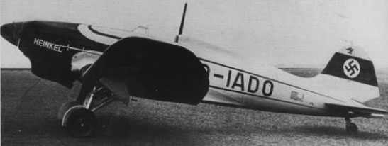
A direct frontal view of the Sopwith Salamander. (Wikipedia)
The Sopwith Salamander: World War Woes
Rear view of the 3rd prototype Salamander. This example has the early rudder. Unfortunately this particular aircraft would be lost in a crash. (Pilots and Planes)
The Salamander would have its first flight on April 27th at Brooklands. The prototype Salamander, E5429, shared the wing mainplane, ailerons and tail control surfaces with the early model Snipe, but these would be improved later on the production models. The improvements were the same as done on the Snipe, which included increasing the size of the rudder. On May 9th, the first Salamander prototype was sent to France for service testing. There is a strange overlap in information with the prototype. Some sources claim that it returned to England on June 30th for further testing at Martlesham Heath, but others claim the prototype was lost to a crash in France on May 19th. Perhaps this was confused with the 3rd prototype, which did crash at a later unknown date. By this point, the other two prototypes were completed (E5430 and E5431). Testing found that the aircraft performed well, but problems appeared with the controls, which were found to be sluggish due to the extra armor.
The Salamander did have its fair share of critics, with several pilots being harsh towards the slower controls of the aircraft and some even finding the concept of an armored aircraft a waste of resources. Many of those who were strong critics of the aircraft criticized it as they did conventional fighters of the time, glossing over its specialized role of ground attack and arguing its armor would make it sluggish in a dogfight, when the aircraft was never intended to operate as a dogfighter. Originally, a plan for 6 prototypes was made but the last 3 were canceled. The 3rd prototype would stagger its machine guns to accommodate the increased amount of ammunition the Salamander had over the Snipe. This change would be present on all Salamanders going forward. With the aircraft performing well in testing, an initial order of 500 aircraft was requested in the early summer months of 1918. Sopwith would begin building production Salamanders at their factories, being constructed alongside the Snipe. In addition to Sopwith, several other aircraft manufacturers would begin constructing Salamanders as well; Air Navigation Co Ltd, National Aircraft Factory No.1, Palladium Autocars Ltd, Glendower Aircraft Co Ltd and Wolseley Motors Ltd. The production versions differed from the prototype Salamanders, having the larger tail fin and rudder as well as the ailerons from the production Snipes being fitted, as well as the staggered machine guns from the 3rd prototype.
A production line at a Sopwith factory where both Salamanders and Snipes are under construction. The first row are incomplete Salamanders. (Armament of British Aircraft)
As the year went on, production for the Salamander increased, as the order jumped from from 500, to 600 to 1400 by the war’s end. Producing the Salamander was found to be more difficult than the Snipe, thanks to its complicated wiring due to the extra steps of creating the armored cockpit area. Problems also began to be found with the armor, as the box was found to warp after some time and distort the frame. This was not a known problem at first, but it plagued many of the early production versions after the war. In October, production Salamanders began being painted in unique disruptive camouflage patterns. This practice started on the 3rd prototype. This would be one of the first times the RAF would officially camouflage paint aircraft, something that would eventually become a mainstay in the next World War. By early November, two Salamanders were sent over and stationed in France, with one being assigned to No 86 Squadron at Phalempin. No 86 Squadron had just been assigned as a dedicated ground attack unit when it arrived. Back in Britain, squadrons No 95 at Weyton, and No 157 at Upper Heyford were also reworked to be dedicated trench fighting squadrons and equipped with five Salamanders each. No 157 Squadron was scheduled to leave for the front on November 21st. With production rapidly increasing and the aircraft soon to be used at the front, all of this was suddenly brought to a halt when the Armistice was signed on November 11th.
Postwar Mediocrity
A Sopwith Salamander showcasing its unique camouflage livery (RAF Museum)
With the signing of the armistice, all plans to ship the Salamander-equipped squadrons to the front were canceled. Production was soon to be cut short as well, as the need for such a specialized aircraft disappeared. Gradually, the order of 1400 was decreased to a much smaller number. Sopwith and Glendower continued producing the Salamander until mid 1919, when total production was completely halted. The other companies mentioned before either stopped production entirely or produced only a few more Salamanders after the Armistice. The Salamander was prepared to be used in full force had the war continued into 1919, with an expected thirteen full Salamander squadrons stationed in France by May. There were expected delays with the production of the Bentley engine, so five of these squadrons were to be equipped with the aforementioned Clerget engines. The exact number of Salamanders produced varies from source to source. The most common number found is that 210 were produced in total, but other sources claim that the actual number is closer to 300. Others claim that almost 500 were built. None of these numbers can truly be confirmed but it is likely much more than the commonly thrown around 210.
Rear view of a Sopwith Salamander (Imperial War Musuem)
Postwar, the Salamander did not find itself too popular, as many issues rose up with the design. The warping of the armor began to become a serious problem on early production Salamanders and it was also found the first 70 Salamanders built by Sopwith had upper wings from Snipes, which were not capable of supporting the heavier Salamander. All of these 70 aircraft were found to be extremely dangerous to fly and it took until December of 1918 for the problem to be realized and fixed. From what can be gathered, most of the production Salamanders were put into storage after the Armistice, with many being finished and immediately sent into storage. Flight testing of the type continued until 1920 despite all interest in the Salamander seemingly being lost in mid 1919.
In addition to the disruptive camo, there is mention of a Salamander being painted in a type of lozenge camo, similar to German aircraft schemes in the war, but no photos are known to exist. It was to be tested at Farnborough alongside the regular camo in July of 1919 but it was unlikely anything became of the tests. Despite the lack of interest, the Salamander did occupy a number of squadrons post war, however the details of where and when are sparse. The latest Salamanders mentioned in RAF service were a squadron stationed out of Egypt in 1922. This would have coincided with the Chanak Crisis against Turkey. A few Salamanders were sent to foreign nations for testing. An unknown Salamander was sent to France to be tested by the Section Technique de l’Aéronautique (Aeronautical Technical Section) in Villacoublay, France. Salamander F6533 was sent overseas to America for trials and testing by their Army Air Service. No further orders or Salamanders were made by America after this and the sole example was known to have been still at McCook Airfield as late as 1926. It is likely the warping issue happened with this particular aircraft, as beneath the cockpit “This machine is not to be flown.” was printed and was seen in photographs of the aircraft.
Salamander F6533 at Mccook Airfield (Pilots and Planes)
Many combat aircraft of the First World War found new life in the following years in the hands of private collectors or attending airshows for spectacular performances. The Salamander was unfortunately not one of these aircraft due to its specialized nature and slower performance compared to the fast aircraft that were featured in such displays. With the purpose of the aircraft now gone and with no future in sight, the Salamander was left to be forgotten as newer aircraft replaced it in squadrons and eventually all would be scrapped. None survive to this day.
Conclusion
The Salamander was one of the first British attempts to create a dedicated ground attack aircraft. In addition, it first tested camouflage patterns on RAF aircraft. Unfortunately, it came too late, if only by a few weeks, to be tested in combat. With the war over and the need for such an aircraft gone, the dream of the Salamander strafing enemy positions died and it fell into obscurity as the type was eventually completely scrapped. Had it entered combat, it would have encountered the same problems it did postwar, which would have left the aircraft prone to accidents of its own design and would have taken time to repair in the field. A strange, and perhaps sad, note is the Salamander was the last Sopwith aircraft to enter service with the RAF before the company became defunct in 1920.
Variants
Sopwith T.F.2 Salamander Prototypes – The first prototypes for the Salamander had many of the same features as the Snipe, including sharing the mainplane, unstaggered guns and the tailplane was supported by wires.
Sopwith T.F.2 Salamander Production – The production version of the Salamander had staggered guns, provisions for carrying bombs, and the tailplane was supported by four steel rods. The first 70 production aircraft accidentally were equipped with the upper wings of the Sopwith Snipe.
Operators
United Kingdom – The Sopwith Salamander was built as a dedicated Trench Fighter for the Royal Air Force, but hostilities would stop before it could be sent to the frontlines. After the war, most Salamanders would be put in storage, but a few would be sent abroad, such as to Egypt.
United States of America – A single T.F.2 Salamander (F6533) was sent to McCook Field for testing.
France – A single T.F.2 Salamander was sent to France for testing with the Section Technique de l’Aéronautique in Villacoublay, France.
A Ta 152H undergoing compass calibration. (flugrevue)
Introduction:
Throughout the Second World War, the job of the interceptor would become ever more challenging. Their targets, mostly bombers and photo reconnaissance aircraft, would fly ever higher and faster thanks to new advancements in turbo and supercharging. With Germany under a state of permanent siege and surveillance by aircraft like the Boeing B-17 and De Havilland Mosquito, it was clear the Luftwaffe needed a specialized interceptor to effectively reach these high flying threats and the multitude of new fighters that were appearing in growing numbers. After several failed attempts to develop the Fw 190 into such an interceptor, Kurt Tank designed the Ta 152H. The short lived design incorporated all of the available developments in high altitude flight available to German aviation in an attempt to create the ultimate high altitude fighter.
High altitude threats and Interceptors
In the summer of 1941, the Mosquito was making its first reconnaissance sorties and becoming one of the gravest threats to German aerial defenses. Operating above 7km and capable of reaching speeds upwards of 560 km/h, the aircraft was almost untouchable after it had reached its destination. Once they had taken their photos, they turned for home and entered a shallow dive that allowed them to accelerate to speeds beyond those of pursuing fighters who were not already chasing them from a higher altitude. With such a small interception window, they were a chief concern to the Luftwaffe. Doubly so were the bomber variants of the aircraft, which raided targets all over North Western Europe.
The following year saw the entrance of the United States into the Second World War, their air force possessing some of the most capable high altitude aircraft at the time. Investments in engine turbocharging allowed them to field a number of bombers and fighters with exceptional high altitude performance. B-17’s were conducting regular operations above 7 km. At first, they undertook operations at significantly lower altitudes, never straying too far from their air bases in southern England, but it was becoming clear that they would soon pose a threat that the Luftwaffe was ill equipped to combat.
The De Havilland Mosquito was quickly recognized as a serious threat not long after its introduction. Photorecon versions, like this later Mk XVI here, could surveil Germany with little fear of interception. (wikimedia)
The only two fighters of consequence employed by the Luftwaffe, the Bf 109 and Fw 190, were effective low to medium altitude fighters. However, through 1942, both were operating with engine power restrictions, and supercharger related performance bottlenecks. While inferior alloys and lubricants were causing a variety of issues, that was less of a concern than the engines themselves not being designed for use at high altitudes. The Bf 109G’s DB 605A, with its variable single stage blower, provided a full throttle height of roughly 6.5 km, depending on the variant. The Fw 190’s BMW 801, with its significantly simpler, single stage, double speed supercharger, was even worse off. Its critical altitude was only roughly 6 km, leaving it, and the 109, distinctly lacking in power at the over 7.5km B-17’s often flew at. Above these altitudes, neither engine could maintain the manifold pressure needed for combat power, putting them at a distinct disadvantage in trying to catch the Mosquito, or fighting American high altitude fighters which were soon making forays into German airspace. As the USAAF began its strategic bombing campaign against Germany proper, there were deep concerns within the Luftwaffe about the battle they were soon to fight, and for which they were clearly technically unprepared for. Even more concerning was the fear that the RAF would soon be operating the Vickers Wellington V bomber, which was reportedly capable of operating at an almost untouchable altitude of 12 km. They never entered service, but were the impetus for the creation of a specialized high altitude fighter with the Höhenjäger program.
With these anxieties building, the RLM convened a conference on the development of high altitude fighters on May 20, 1942 at Messerschmitt’s plant in Augsburg. In addition to the high altitude British bomber, further concerns were spelled out over the recent study of the new Merlin 61 engine, which, with its two stage, two speed supercharger, promised to make the Spitfire and Mosquito even more challenging opponents at high altitude. Of particularly grave concern was that the German aviation industry could not simply follow the same development path as the Allies. The poor qualities of their available alloys and the inadequate supplies of high octane fuels meant that even, if they had a factory furnished with all the tools to manufacture an engine like the Merlin 61, they simply could not build or operate it with the materials at hand.
As such, they had to pursue less conventional means of improving performance. Messerchmitt proposed a redesign of a former naval fighter proposal for high altitude use. The Me 155 carrier based fighter design, with its very long wingspan, was proposed to be converted for high altitude use, the work being done mostly at the S.N.C.A.N plant in Paris. The design would later be taken up and heavily altered by Blohm & Voss, who went on to design the Bv 155, with turbochargers and GM-1 nitrous boosting. Neither design came to fruition. A secondary design, the Bf 109H, would involve stretching the wingspan of a Bf 109F, and later G, and installing the high altitude GM-1 engine boost system. Likewise, this design was not pursued. In the end, Messerschmitt would go on to design a mass production, high altitude variant of their standard Bf 109G with a pressurized cockpit and nitrous boosting. While it would prove fairly adequate for the time, it was held back by the need for GM-1, which was difficult to transport in large quantities without a pipeline.
Focke-Wulf would face an even greater challenge with their program. While their Fw 190 was proving to be among the best medium altitude fighters of the war, its short wingspan and outdated supercharger meant it would take a considerable effort to make a high altitude fighter out of it.
The Höhenjäger Fw 190
Focke-Wulf first pursued turbocharging to get their fighter to reach the adequate level of performance for the Höhenjäger project. Almost immediately, they ran into the issue that it was almost impossible to fit a suitable turbocharger into a Fw 190A, though an externally mounted, and almost completely unwieldy unit was suggested. The first serious effort came with the proposal for the Fw 190B fighter, or Höhenjäger 1, in August of 1942. The design would take the then in production Fw 190A-3, increase its wingspan from 10.5 to 12.4 meters (increasing its area from 18.3 to 20.3 m^2), and install a pressurized canopy. The engine was initially unmodified and nitrous boosting was not pursued, in the hope a suitable turbocharger would be developed. The prototype, Fw 190V-12, began testing, but was abandoned in favor of using older, pre-production Fw 190A-0 prototypes before moving on to pre-production. The Fw 190B-0 received the new BMW 801 D-2 and several other modifications going into the new A-5 fighter. It began testing in December of 1942, and despite some faults with the pressurized canopy, which were later corrected, the aircraft had considerably better high altitude handling than the original A model. All four of the A-0’s were converted, but the program showed little promise. Despite the effort, the improvements were not enough and the aircraft was still too slow at high altitude. It was clear that the aircraft needed a heavily modified, or entirely different engine, in order to attain the level of performance needed.
Perhaps the most promising development for the next generation of the Fw 190, the C series, hoped to install a much more powerful DB 603 engine. Harsh teething issues and limited supplies for the engine doomed the project. (grafiq)
In parallel with the B-project, the decision was made to re-engine the aircraft with either the Junkers Jumo 213, or Daimler Benz’s DB 603. Both promised better high altitude performance over the BMW 801 along with a considerable overall increase in engine output. The DB 603 project would proceed with the designation Fw 190C, and the Jumo 213, Fw 190D. The first Fw 190C prototype, V13, had a DB 603 installed, with an annular radiator at the nose of the aircraft and its supercharger intake mounted between its two oil coolers, these modifications presenting a longer, but more streamlined profile. Little drag was added to the airframe with the modifications initially, but they would be forced to mount the supercharger scoop externally. The aircraft first flew in March of 1942, and overheating, along with general teething issues would be noted. Two more prototypes were converted, V15 and 16, receiving the longer wing from the B-project and GM-1 equipment. Turbocharging was also proposed, but not pursued until much later on. The program continued through May at a decent pace and they were achieving high speeds, one aircraft reaching 696 km/h at 6,950 m, but overheating and engine failure remained serious issues. Similar problems were likewise being experienced with the Jumo 213. The results, however, prompted Focke-Wulf to expand the program with six more prototypes, V13,15,16, 19, 20, 21, 25, 26, and 27 carrying the DB 603, and V22 and 23 using the Jumo 213. Despite the focus on the DB 603, the company was prepared to switch to the Jumo 213, which they could obtain a much larger supply of.
The large, drag inducing turbocharger scoop earned this aircraft the moniker ‘kangaroo’. Aerodynamically unsound and mechanically unreliable, it proved unsatisfactory for service. (wwiiforum)
The final design for the Fw 190C featured the DB 603A with its supercharger intake mounted on the port engine cowling, with various provisions for an armament of MG 131 machineguns, MG 151/20, and MK 108 autocannons. Its highest tested speed was an impressive 722 km/h at 9 km, with an experimental DB 603G engine, and without armament or armor plates. Production was strongly considered, and then canceled. The DB 603, in its fighter configuration, was still proving troublesome, and V13 was written off after an engine failure forced the pilot to crash land. The engine itself had a comparatively small production run compared to the Jumo 213, and was being shared with a number of twin engine bombers and night fighters. As the older, and massive Jumo 211 production lines were transitioning to the more powerful Jumo 213, it was by far the better choice for a new mass production fighter.
The Fw 190D or ‘Dora’ project continued, though its development path did not lead to a mass produced, high altitude fighter. Rather, it became a project to facilitate getting the Jumo 213 into a fighter as fast as possible, as it was one of the few German engines capable of competing with Western Allied models in most areas. The only mass produced variant, the D-9, is often mislabeled as a high altitude fighter, though its engine was designed for low to medium altitude use. A small number of high altitude models, with the appropriate engines, were produced, but were nothing compared to the D-9’s production run of well over a thousand aircraft by the end of the war.
Shifting programs aside, Focke-Wulf would continue with the new Höhenjäger II project, now seeking to build a truly superb high altitude fighter by taking several of the Fw 190C prototypes and equipping them with Hirth TK 11 turbo-superchargers. With the Fw 190B improvements, the 2000 hp DB 603 S, and a pressurized cockpit, it was hoped that a number of exceptional high altitude fighters could be produced, even if they could never reach the production figures of the Dora. They attempted to solve the earlier issue with the unmanageable size of the turbosupercharger by installing it partially outside of the fuselage, with an air scoop at its front. V18 received the necessary modifications and flew in December of 1942, with serious cooling problems being noted. Further modifications were made after the first several flights, most notable being that a larger oil cooler was mounted, the tail was enlarged to improve high altitude control, and the next prototype, V30, was re-equipped with a four bladed Schwarz propellor. Their extreme high altitude performance was superior to the C, with the aircraft reaching a speed of 670 km/h at 11 km, though they were proving far more temperamental. Turbine and engine issues continued to cut test flights short, though more prototypes were constructed through early 1943, V29 to V33. However, turbine issues persisted, and the entire scoop set up was found to be aerodynamically poor, and the design was proving very disappointing in comparison to the fully recessed models in service with the USAAF. Its performance too was deemed inadequate, and the project was canceled.
Falling behind
Apart from expedient designs, like the GM-1 boosted Bf 109’s, German efforts to produce a high altitude fighter had largely stagnated during 1943, and by the beginning of 1944, they were at a distinct disadvantage. For the past two years, most of the aero engine industry was working hard to modify their existing models to run at their full power using the inferior materials and fuel that were available to them. Among the clearest problems this caused was with the Messerschmitt Bf 109 G, or ‘Gustav’ model, which was only finally cleared to run at its full combat power in the summer of 1943, almost two years after its introduction. Under such conditions, developing new engines was a mostly hopeless effort, and to make matters worse, Allied developments in this field were unfolding brilliantly. While Focke-Wulf and Messerschmitt had failed to deliver on their high altitude fighters, the RAF began to fully transition to the use of the two-stage Merlin in their Spitfires, while the even more powerful Griffin was in development. By the end of 1943, USAAF finally introduced the P-51B, using a licensed Packard Merlin engine, and the P-47 had seen significant performance improvements which gave it unparalleled performance above 9 km. The P-51 proved perhaps the most concerning, as it not only had the benefit of a significantly more advanced engine, but it had been designed with aerodynamic concepts that were not available to aircraft designers before the war. It was an altogether modern aircraft, whereas the German air force would remain dependent on modified versions of planes which had been flying before the war had begun. The Bf 109G had fallen behind its Western contemporaries in most areas of performance, while the Fw 190 still clung to a competitive edge in low to medium altitude engagements. At high altitudes, especially above 7.5 km, there were only a comparative handful of GM-1 boosted Bf 109G’s that could really challenge the Allies, and even then, not on equal terms.
Germany did not possess the materials needed for robust and reliable exhaust valves, bearings, or more efficient, high pressure, high temperature radiators like those on Western Allied planes. However, there were areas of hopeful improvement. Foremost was that, by the autumn of 1943, German engine manufacturers had developed nickel coatings for engine pistons to overcome corrosion problems, and had modified the DB 605’s oil scavenge system to allow it to run at its originally planned combat power. While they would not be able to produce engines as reliable as those in the service of the RAF and USAAF, it was clear that the performance disparity could be reduced. Just as crucially, improvements were being made in regards to radiator design, particularly the annular units which were being tested on the high altitude Focke-Wulf projects. The new AJA 180 on the Fw 190 series was both approaching the pressure and temperature tolerance of Allied models, and was very compact, allowing the Fw 190 to retain its aerodynamic sleekness even when it switched engines.
The Fw 190D project transitioned away from high altitude fighters when the demand for better general purpose fighters grew. Rushed into production, it had more than its fair share of blemishes but, nonetheless, was an effective successor to the earlier ‘Anton’. (worldwarphotos)
While Messerschmitt had already succeeded in producing an acceptable high altitude fighter in the GM-1 boosted Bf 109G, Focke-Wulf’s projects took a different turn. The high altitude Fw 190D project shifted focus to produce a medium altitude fighter, the Fw 190D-9, and another project would seek to build a successor to the Fw 190, the new plane being named Ta 153. The designation changed to reflect Kurt Tank’s role as the head designer at Focke-Wulf. With this new design, hopes for significant high altitude improvements were again stoked, but as had become clear by their earlier failures, such improvements could not come from any unfamiliar solutions or technically complex methods, like turbocharging.
The Successor
The Ta 153 was so designated as it was not a variant, but a successor to the original aircraft. It featured a new fuselage and wings and the occasionally troublesome electrically driven landing gear actuators were changed for hydraulically driven ones. Being almost entirely divorced from the Fw 190’s supply chain, it was thus denied for production in March of 1943, given the amount of labor and time it would take to set up tooling. A compromise model between the design and the Fw 190D was selected, designated the Ta 152.
The Ta 152C program attempted to replace the Fw 190 A&D and correct the faults of the Dora. In the end, it proved too similar to justify shifting production before the end of the war. (ta-152.de)
There were several types planned, namely Ta 152 A,B,C and H. These were standard fighters, heavy fighters for use against bombers, fighter bombers, and a high altitude interceptor. The A and B were designed to use the Jumo 213A & E, respectively, the C the DB 603, and the H, the Jumo 213E. To avoid impacting the production of the Fw 190D, the high altitude model was the first to be developed. These planes featured a hydraulic landing gear system as opposed to the electric actuators on the Fw 190, an improved vertical stabilizer from the Fw 190C program, larger wings, and a half meter fuselage extension in the rear fuselage, with the ensuing redistribution of weight helping to correct for an issue with the aircraft’s center of gravity.
While it may seem odd that they were essentially pursuing two fighter designs to succeed the Fw 190A, the Luftwaffe was desperately looking for higher performance fighters. Hopes were placed on the new Jumo 213 in the Fw 190D, and the new DB 605D in the Bf 109K, to keep pace with the Allies. The Dora was an expedient solution which could use the same supply chain as the original fighter, and the Ta 152 would be a more thoroughly improved model which would be transitioned to once the Dora’s supply chain was well established. In any case, only the high altitude Ta 152 variant was pursued with any substantial amount of resources, given it would be assigned a mission the Bf 109K and Fw 190D models were not suitable for. Jets were, of course, also quite promising, but they were still an immature technology, and it was clear that the leap from pistons to turbines could not be made in 1944.
The new fighter would be designed with both high altitude and low altitude performance in mind. To meet this challenging requirement, both the GM-1 high altitude, and MW 50 low altitude engine boost systems were to be installed aboard the aircraft. Kurt Tank selected several of the old Fw 190C prototypes to be converted for the new program, these being V18, 29, 30, 32, and 33. V33 was the first to undergo modification and was redesignated V33/U1, now featuring a three bladed VS 9 propeller, a forward fuselage lengthening of .5 meters, a rear fuselage lengthening of 0.772 m, a new high aspect wing with an area of 23.5m^2, a hydraulically actuated undercarriage, and two 20 mm MG 151/20’s mounted in the wing roots.
It first flew on July 13, 1944, and was lost after it crashed during its 36 minute test flight at Vechta. The second prototype, V30/U1, flew on August 6, and like the first, was again lost, though this time resulting in the death of its pilot, Alfted Thomas. More success was had with the third prototype, V29/U1, which flew on September 29, 1944, and the fourth, V18/U2, which flew shortly after. With pre-production beginning in November, this left them about a month to perform flight tests on their surviving prototypes. Serious trouble with the program was encountered as late as November, when test pilot Hans Sander had to crash land his aircraft after his engine seized due to fuel starvation. It was found a hydraulic valve had been installed in the fuel line, an accident most likely a result of the aircraft’s rushed development.
The losses and damages experienced at this point in testing were threatening to seriously interrupt the pace of the project, but in the end, they rushed through development with some of the stability issues unresolved. This effectively led to the aircraft entering production with only slight adjustments from the prototypes. However, the plane was achieving good high altitude performance, both in terms of speed and ceiling. Test pilot Friedrich Schnier would fly V29/U1 to an incredible height of 13.6 km on January 20th, 1945. Beyond this, the fourth and final converted aircraft was V32/U1, which was fitted with a four bladed Schwarz propeller and the new MG 213 revolver cannon. It first flew in January of 1945, though none of the equipment would be worked into any production aircraft.
The eccentric profile of the aircraft, with its high aspect ratio wings. (destination’s journey)
The H was unique among the Ta 152 series, with its long, high aspect wings designed for high altitude use, a pressurized cockpit, and the installation of both the GM-1 high altitude, and MW 50 low altitude boost systems. While together, they promised incredible performance at any height, GM-1 was never carried aboard any of the operational fighters due to its container’s adverse effects on stability. Eager to have this aircraft as soon as possible, Focke-Wulf sprinted through its development, and the Ta 152H entered pre-production in November of 1944. The extremely rapid pace of development was emblematic of the very desperate situation the German air force was in at the time. This resulted in the delivery of an aircraft that was effectively unfinished.
The Ta 152H-0 entered service without several of the key features that the plane was set to carry, lacking the outer wing fuel tanks, and the engine boost systems. As such, it was considerably lighter, and better handling than the planned production model, but without the boost systems, it was much slower. For the time being it judged necessary, as there were serious weight distribution issues with wing fuel tanks and boost systems aboard. While it was designed with wing tanks, GM-1, and MW 50, the production model of the aircraft would not be permitted to fly with all three. In the end only the MW 50 and the wing tanks were permitted to be used together, but the GM-1 system would prove more troublesome. A stop gap solution late in the war would allow for the use of GM-1, but only GM-1. By the time the war ended, there was still no solution on how all three pieces of equipment would be added to the plane without jeopardizing its flying characteristics.
It was in this rough state when it was delivered to the Luftwaffe for testing in December. Due to supply chain issues, production was slow and the aircraft were finally delivered to the Luftwaffe until January 27, 1945.
Operational History
Given their very late introduction during the war, the Ta 152H saw very little action and its combat record is extremely limited. The aircraft was only supplied to the Stab, the squadron staff group, and Gruppe III of JG 301, a dual night and day fighter squadron which transitioned to them from Fw 190A-8’s on January 27. The squadron had a good pool of experienced pilots already familiar with Focke-Wulf aircraft, though their mechanics would have a far more difficult task, as the Ta 152H-0 had been pushed into service without maintenance manuals. At the airfield at Alteno, they received 11 aircraft, with 16 others having been destroyed or damaged on the ground before they could reach the unit. Familiarization and training proceeded until the end of February and was not without incident. One aircraft (150037) was lost in a training incident, a second damaged but repaired, and serviceability fell from 75% to 30% after an incident with water contaminating fuel supplies. The squadron would go on to receive several more aircraft before rebasing to Sachau when Alteno was overrun. They would attempt to engage Allied bombers on March 2, but the 12 Ta 152H’s would fail to reach them, as they were attacked by the Bf 109s of another squadron which mistook their unfamiliar planes for the enemy. No aircraft were lost in the engagement. A second high altitude interception against a DeHavilland Mosquito was also attempted, though engine trouble forced the pilot to return to base before contact was made. Despite these incidents, there was some high altitude use of the Ta 152H, most notably during free patrols, where their cruise altitude was at or over 7 kilometers. At such heights they would excel, offering near unparalleled performance, though most of their engagements would happen at much lower altitudes.
One of the only photographs of Ta 152H’s in operation with JG 301. (destination’s journey)
The unit rebased again to Stendal near Erfurt, where they joined JG 301’s Gruppe II, during which one aircraft was lost, and the pilot, Jonny Wiegeshoff, was killed on the landing approach. This was believed to be the result of the propeller reduction gear failing and becoming stuck in an almost feathered position. By March 14th, the understrength unit was supplied with several Fw 190A-9s. Outnumbered and with little security, the Ta 152H’s often flew top cover for the rest of the unit during what few operations were undertaken. On April 10, Erfurt was contested, and during the fighting, the eight serviceable Ta 152’s engaged a flight of fifteen P-47’s near Brunswick, resulting in one victory claim.
Gruppe III’s last actions were conducted from Neustadt-Glewe. On April 15th, the unit suffered its first combat loss. During operations that day, four Ta 152s sortied to attack a pair of RAF Hawker Tempests engaging in a low level sweep. According to Obfw. Willi Reschke, the Ta 152H in the number two position, flown by Obfw. Sepp Sattler, suddenly lost control and crashed before contact was made, seemingly suffering a fatal malfunction. However, other accounts claim he was brought down by one of the RAF Tempests. The remaining two Ta 152’s engaged the Tempests of No. 486 Squadron. In the ensuing battle, Obfw. Willi Reschke entered an intense, low level dogfight with one of the Tempests. Near the beginning of the engagement, he fired on and struck the tail of a Hawker Tempest flown by Lt. Mitchell, his gun’s electrical circuit seemingly failing shortly after. However, when Mitchel attempted to turn away from his opponent, he lost control of his damaged aircraft and crashed. From his experience here and in other engagements, Reschke swore by the low speed maneuverability of the Ta 152, which he felt was critical to his survival through the last days of the war. On their return, the Ta 152H flown by the Schwarm leader, Oberstleuteneant Fritz Auffhammer, suffered an engine failure, though the pilot successfully restored power and returned to base with his supercharger broken. Sattler and Mitchel were both buried at a cemetery in Neustadt-Glewe.
The last actions of the squadron were in the last stages of the Battle for Berlin, and on April 24th, the Ta 152s and Fw 190As of the IInd and IIIrd Gruppe attacked Soviet positions and engaged Yak 9’s. The final mission was flown over Berlin in poor conditions, and during an engagement with a flight of four Yak 9’s, Hauptman Hermann Stahl was killed during the engagement, with the four Yak-9’s being claimed by the unit. After the surrender, the unit rebased to Leck in Schleswig-Holstein, where they were disbanded and one of the serviceable Ta 152H’s was transferred to England by the RAF so that it could be evaluated. A second Ta 152H was also claimed by the USAAF for evaluation purposes, the plane being another H-0 which likely belonged to a testing unit at Rechlin.
One of the only serviceable planes was taken to the UK for testing. The other was taken in hand by the US. (Alessandro Orseniga)
In all, the Ta 152H was never actually used for any high altitude combat operations and its service was restricted to a single under strength unit. With at most ten victories and four operational losses, it is difficult to give any appraisal for its performance from its brief career with JG 301. Obfw. Josel Keil, was the only pilot to qualify as an ace on the Ta 152H, and together with Willi Reschke, who had two credits in the Ta 152H, and 24 in other aircraft, held nearly all of the aircraft’s combat credits between them.
Handling and Flying Characteristics
While the Ta 152H’s combat record leaves a lot of questions left unanswered, most pilots who had the chance to get behind the controls of the aircraft can at least agree that the aircraft flew very well. Among its most famous advocates was Royal Navy Test pilot Eric Brown. He would praise its excellent climb performance, maneuverability at high altitude, stability, and good landing characteristics. His only negative remarks were that its roll rate was reduced over the older Fw 190A, that its stick forces were notably heavier, and that its wheel brakes were still awful and prone to fade after a few moments of use. He otherwise considered it an excellent aircraft and the best high altitude piston engined fighter he had flown, comparing it favorably to a Spitfire Mk IXX. It must be noted that he misidentifies the aircraft as an H-1 in his book, and not the substantially lighter H-0, which is visually identical.
Captain Brown’s remarks are matched by those of the pilots who assessed the aircraft in the Stab and III/JG 301. The Ta 152H-0 had the best evaluation received by a front line operator of a Focke-Wulf aircraft. The aircraft possessed most of the best qualities of the earlier Fw 190D-9 without having its poor accelerated stall characteristics. While still described as uncomfortable to sit in like the Fw 190D it was so similar to, its handling was much improved and less prone to the aggressive snap rolling. So, while the aircraft was less maneuverable, generally speaking, most pilots were more comfortable pulling harder turns. In tests at the unit, some new pilots in Ta 152H’s were able to turn with seasoned pilots in Fw 190A’s. Take off runs were short, and the landing approach could be conducted at low speeds. Generally speaking, it was a fairly forgiving aircraft. The only negative notes on the aircraft were from the findings of the Rechlin Test Center, which found the aircraft became seriously unstable in dives exceeding 600 km/h and that level flight required excessive trimming of the horizontal stabilizer.
The enlarged tail and redesigned wings helped give these aircraft better handling characteristics than the Fw 190D. (Grafiq)
The stick forces were notably fairly high, but they were harmonized well, and the push rod control system ensured inputs were very responsive. Stability about the vertical axis was poor, and there was a tendency to skid. This tendency grew worse at higher altitudes and motivated the designers to install a level flight autopilot. The aircraft possessed good visibility to the back, sides, and rear, with the view over the nose being mediocre to poor. The controls were placed conveniently, with the instrument panel layout being clean and easy to read.
Most of its good qualities were not found in the fully equipped H-1 production model of the aircraft. Numerous problems were encountered when the full set of engine boosting equipment and fuel tanks were installed and filled. The added weight of the boost systems and wing tanks was substantial, and asymmetric. The GM-1 system and the wing tanks were particularly problematic, and the aircraft was unstable if the GM-1 container and fuel tanks were filled. Stability with the GM-1 system was only possible with a ballast kit, empty wing tanks, the removal of the MW 50 system, and a set fuel limit for the rear fuselage fuel tank. These issues were not resolved by the time the war ended, and there was no way the aircraft could use any combination of these systems without seriously jeopardizing its flying characteristics.
Mechanics generally found the aircraft easier to maintain than the Fw 190, however there were some issues. The new hydraulic system for the landing gear experienced teething and quality control issues. The position of the landing gear wheel well was also found to be at issue, as when launching from damp conditions, the propeller cast mud and water into the well, which made its way inside the wing. This caused issues with the hydraulic systems and the autocannons fitted in the wing root.
Comparisons with contemporary fighters
The Ta 152H represented a leap in Germany high altitude fighter design, though not necessarily one that took them beyond the competition. (flugrevue)
Aircraft (manifold pressure)
Speed at Sea Level (km/h)
Speed 3050 m (10,000 ft) (km/h)
Speed 6096 m (20,000 ft) (km/h)
Speed 9144 m (30,000 ft) (km/h)
Speed 9.5 km (31,168 ft) (km/h)
Ta 152H-1 (1.92 ata)
580
640
690
725
732
Fw 190D-9 (1.82 ata)
611
645
689
653
645
P-51B-15 (75″ Hg)
616
675
709
688
685
P-47N-5-RE (72″ Hg)
587
643
708
740
759
P-47M (72” Hg)
587
646
701
753
762
P-38L (60” Hg)
550
608
646
663
659
Spitfire Mk 21 (+21 lbs)
592
658
700
704
703
Me 262 A-1a
800
x
870
845
x
*The Ta 152H-1 could reach a maximum speed of 760 km/h at 12.5 km using the GM-1 boost system. Other issues put operating heights lower. The Fw 190D-9 represents a late model, having received an MW 50 boost system, as was available near the end of 1944.
The Ta 152 entered service on a battlefield where the Western Allies already had high altitude supremacy, and had a number of improved designs that had yet to make their debuts by the time the war in Europe was ending. By January of 1945, the German air force was no longer dealing just with long range escort fighters over its own soil, but virtually every fighter the Allies could throw at it, such as P-47’s, Spitfires of several marks, La-7’s, and Tempests, just to name a few.
Fw 190D-9 (Graphiq)
Against its contemporary Fw 190D-9 counterpart, it is clear that the Ta 152H did not represent a comprehensive upgrade. The Dora shared much of the same fuselage, though it retained the wings and tail sections of the older Anton series fighter, and it carried the Jumo 213A engine designed for use at lower altitudes. In regards to linear speed and acceleration below 6 km, the Dora roughly matched or exceeded the Ta 152H. This, however, was not the case at higher altitudes, where the high altitude specializations of the fighter showed their worth. The Ta 152H was known to be more maneuverable in flat turns and much more forgiving in most aggressive maneuvers, a result of its high aspect ratio wings which lacked the less than ideal tendency for snap rolling without much warning that the older Fw 190’s were known for. In a dive, the Dora was notably superior, as the aforementioned wings of the Ta 152H made it less stable in high speed dives. The H-1 carried, but rarely made use of, GM-1. This is a discrepancy of several hundred kilograms, leaving the true climb performance of the aircraft somewhat ambiguous, with a claimed 20 m/s at sea level without MW 50.
The P-51B’s and D’s had marginal differences in performance. They were among the most aerodynamically clean fighters of the war, boasting an extremely streamlined fuselage, laminar flow wings, and a radiator scoop which produced thrust that offset upwards of 90% of its own drag. To increase maneuverability in high speeds and in power dives, the control surfaces were internally sealed and used a diaphragm to reduce stick forces. The engine was a Packard Merlin V-1650-7 with an intercooled, two stage, two speed supercharger. Even though the engine was actually geared for lower altitude use than its predecessor, the combination of these features made the aircraft a very fast, maneuverable fighter which could boast of high performance at most altitude ranges.
Against the Ta 152H-1, the Mustang held to a higher top speed at low to medium altitude, better maneuverability at high speed, and far better dive performance. At extreme altitudes, the H-1 outstripped the Mustang in top speed, and across most altitudes would have had better low speed maneuverability. The high aspect ratio wings of the Ta 152 both gave it better handling at high altitude, and much improved stall characteristics over its predecessors down low. Curiously enough, both the Ta 152H and the Mustang were far more maneuverable than their wing loading would suggest, a result of high aspect ratio and laminar flow wing designs, respectively. However, in the Ta 152’s case, this came at the cost of a slower roll rate, and unstable high speed dive characteristics. While the Ta 152H could prove an exceptionally challenging high altitude opponent to all of the contemporary Allied fighters, it was a competitive, but not particularly impressive aircraft at lower altitudes. Performance wise, it could be said to fly like a more maneuverable, if slower, Fw 190D when at lower altitudes.
There is of course the story of Kurt Tank himself escaping a pair of P-51’s at low altitude in a Ta 152 prototype. Near the end of 1944, the designer himself was flying one of the prototypes to a conference in Cottbus, Germany, where he was happened upon by two P-51’s. Using the MW 50 boost system in the aircraft, Tank slipped away from his pursuers and arrived in Cottbus unscathed. Some laud this encounter a sign of the aircraft’s superiority, however, it is not a useful measure of the performance of any of the combat models of the aircraft. At Kurt Tank’s instruction, the prototype in question was unarmed and, more than likely, carrying no armor plate, which would have made the aircraft substantially lighter than any operational Ta 152H fighter.
The Spitfire Mk 21 represented the final evolution of the wartime Spitfire, by then nearing its tenth year in the air. A far echo from the Mk I, the 21 featured a vastly more powerful Griffin 61 engine. Much like its late Merlin powered predecessors, it possessed an intercooled, two stage, two speed supercharger. Unlike them, it was massive and much more powerful. After incorporating structural improvements and modifying controls for high speed, the Spitfire aged perhaps the best of any fighter of the war. Compared to the Ta 152H, it lacked the sheer distance in top speed performance of the P-51, but more than challenged the Focke-Wulf in linear speed and climb rate across most altitudes. However, at and above 7 km, the 152H had a confident advantage in speed and maneuverability.
The P-47N represented the final evolution of the Thunderbolt. Though not destined for Europe, it performed similarly to the P-47M which debuted in combat roughly the same time as the Ta 152H. (wikimedia)
Compared to the most modern Allied high altitude fighters, the Ta 152H lost most of its edge. The P-47N and M represented the final evolution of the American high altitude fighter, featuring a new 2800 hp, R-2800 turbocharged engine, and a variety of aerodynamic improvements to increase control at high speed. By the late Summer of 1944, the Western Allies had already gained air superiority over Europe, and so the new aircraft was stockpiled in the US for use in the Pacific, with the first deliveries being made in September of 1944. There was a similar performing model in Europe, the P-47M, though it was a limited production aircraft designed for chasing V-1 flying bombs and other high speed targets. Teething issues would keep it from entering service roughly until the Ta-125H did, in March of 1945. In the end though, the Luftwaffe had become so degraded that clearly no new updated models would be required and the performance increases would not justify the effort to refamiliarize pilots and maintenance personnel.
In terms of top speed, the P-47M&N handily outperformed the Ta 152H at all altitudes, the only exception being at extremely high altitudes when the Ta 152H employed GM-1. In contrast, the Focke-Wulf enjoyed a better climb rate and was likely the more maneuverable of the two, although it was certainly less capable in a dive. The late war Thunderbolts were certainly the fastest high altitude fighter which saw combat, the Ta 152H’s of JG 301 never having carried GM-1.
The P-38L was the last fighter variant of the Lightning fighter, the first model having been in service prior to the US entry to the war. With its turbo supercharged Allison engines, it was among the first fighters of the war that was designed for high altitude use. However, by the end of the war, it left something to be desired in terms of both its top speed, and like the Ta-152H, its high speed dive performance. Its low critical Mach number meant that the plane encountered compressibility at lower speeds than all of the fighters presented here. At high speeds and altitudes, the plane locked up and would remain uncontrollable until its high speed breaks were deployed, or it had descended into lower, denser air. Of all the Allied high altitude fighters, the Lightning compared fairly unfavorably with the Focke Wulf.
Most easily glossed over is the performance compared to jet fighters, which by the time the Ta 152H was introduced, had been in service for a few months. The Messerschmitt 262 had re-entered service in November of 1944 after earlier operational problems, and once training and maintenance programs were revised, the plane quickly proved itself. While it was slow to accelerate and climb, it was unapproachable in terms of top speed. Extreme high altitude use of the temperamental Jumo 004 turbojet engine was limited, though as a means of attacking high altitude formations of Allied bombers, it was by far the best equipped aircraft Germany possessed. Its slow acceleration meant that any energy-demanding maneuvers were largely off the table, but when flown by a pilot that understood its strengths, the plane was untouchable save for when it was taking off or landing. Though largely an issue post war, the Me 262 demonstrated the difficulty in justifying further piston engine fighter development at this point in aircraft development.
The Ta 152H began production after the Me 262 jet fighter had already entered service, so it, and many other programs, had to compete with it for resources. As the turbojet was already showing to be the future of fighter design, the Ta 152 was difficult to sell to the Luftwaffe. (I.PINIMG)
Overall, the Ta 152H certainly was not a Wunderwaffe by any means. At all but the highest altitudes, the aircraft was not a particularly better performer than its preceding, and much more numerous, Fw 190D counterpart. Even at extreme altitudes, it more than had competition in the form of the Thunderbolt N and M, which not only outstripped it in performance in a number of areas, but beat it into production by several months. It’s only truly exceptional performance was achieved using a high altitude engine boost system, though one that had stark technical and operational challenges. Nevertheless, it represented a stark improvement in high altitude performance over previous German fighters. It too, could boast of extreme maneuverability at high altitudes, even if it didn’t lead the pack in pure speed. Top speed aside, its wings lent it a great degree of maneuverability at high altitude, and its overall performance at and above the altitudes Allied bombers flew at was considerable. This is also to say nothing of its trio of cannons; two 20mm MG151/20’s and its single 30mm MK108, which leant it incredible striking power. While the incorporation of the Jumo 213E, MW 50, and on paper, GM-1, did not produce the pinnacle of fighter design, the result was still a capable high altitude interceptor capable of engaging the highest flying targets of its day.
Construction
The construction of the Ta 152H’s fuselage was essentially that of a modified Fw 190A-8. The fuselage was largely the same with the following modifications: the forward fuselage was lengthened by 0.772 m in order to fit in a Mk 108 autocannon, the wing connecting section was moved forward 0.420 m to correct for the center of gravity, and the rear fuselage was lengthened by 0.5 m. The leading edge of the tail was exchanged for that on the Fw 190C, being considerably larger. Given the deteriorating situation near the end of the war, the new tail surfaces were wood, rather than metal skinned. The fin and rudder were enlarged for better control, with the new surface area of the tail stabilizers measuring 1.77 m2 for the vertical and 2.82 m2 for the horizontal. The changes to the fuselage necessitated strengthening, which saw some duralumin framing elements replaced with steel. In order to reduce the number of new assembly jigs they needed for the production line, the forward fuselage extension was bolted through the former Fw 190A engine attachment points.
The Ta 152H-1 featured all the fuel tanks pictured here, the preproduction H-0 had only those in the fuselage. (Deutchesluftwaffe.de)
The wings were entirely redesigned from the Anton and changed to a high aspect model which increased the wingspan to 14.4 m, and to an area of 23.3 m2. Structurally, it remained a monocoque structure, but its rear spar and leading edge were used to absorb transverse forces and it was structurally reinforced with additional stiffening ribs. The landing gear were the same as the Fw 190A-8’s, but they were hydraulically and not electrically operated. They mounted 740 mm by 210 mm wheels to accommodate the increased weight of the aircraft. The inboard section of the wing mounted an MG 151/20 autocannon with provisions for 175 rounds of ammunition each.
The Ta 152H had a clean and well laid out cockpit and instrument panel, much the same as this Fw 190D-9. (Smithsonian)
The aircraft possessed a pressurized canopy to reduce the physiological stresses of high altitude flight. It was a very rudimentary system, with the cockpit rivets being sealed with DHK 8800 paste, and the sliding hood being sealed by means of a cylindrical rubber tube liner. Pressurization was regulated by means of a 1 liter air bottle supplied by a Knorr 300/10 air compressor which was geared to the engine with no intermediate gearing. The system was engaged at 8 km and maintained a constant .36 atmospheres. To prevent windscreen fogging, it was double-paned, with silica packets installed in the gap. Quality control issues saw varying effectiveness at altitude. On the record setting flight, Friedrich Schnier reported the system leaked badly above 12 km and shortly after he suffered joint pain, impaired vision, and numbness in his extremities due to low air pressure.
The Ta 152H carried an armament of two MG 151/20 20 mm cannons in each wing root and a centerline MK 108 30 mm cannon which fired through the propeller hub. The 20 mm guns were supplied with 175 rounds per gun, and the 30 mm with 90. The gunsight was the standard Revi 16b sight, which was eventually supposed to be replaced by the new EZ 42 gyroscopic sight which, when properly used, gave the pilot an accurate gunsight lead against his target. The aircraft was well armored with two engine plates, and six to protect the pilot, with a combined weight of 150 kg. The 8 mm plate behind the pilot was judged inadequate, though plans to increase its thickness to 15 mm were not carried out. A single hardpoint could be attached to the underside of the aircraft to install a 300 liter drop tank, but there were no provisions for carrying bombs.
The engine was a 35 liter Jumo 213E inverted V-12. Originally developed from the Jumo 211, which saw heavy use in bombers much earlier in the war, the new Jumo 213 was what most of the Luftwaffe’s hopes were placed on to compete with newer, more powerful Allied engines. It featured a new AJA 180 streamlined annular radiator that supported the oil and engine coolant. Critically, it was able to operate at significantly higher temperatures and pressures than older models, though not quite at the standards of the Western Allies. However, unlike Allied models, the Jumo was heavily automated. The Bediengerat, or control device, was an electro-mechanical computer that managed the propeller RPM, mixture, supercharger speed, and radiator based on the pilot’s throttle inputs. This helped to relieve the pilot’s workload, as the similar Kommandogerat did on the BMW 801 powered models.
The Jumo 213E was the high altitude model which featured an intercooled, two stage, three speed supercharger. To further improve on high altitude performance, the aircraft would use a GM-1 nitrous boosting system. The system consisted of an 85 liter tank behind the pilot, which was fed into the supercharger by a pump when the system was activated. As an oxygen carrier, the job of the nitrous is to provide an oxygen rich mixture to the engine when the supercharger is operating at altitudes where it is unable to provide the compression, and thus enough oxygen, needed to maintain high engine output. For the Jumo 213E, this was above 11 km. The drawbacks of the system were its uselessness at lower altitudes, its poor compatibility with the third speed setting on the supercharger, and the bleed off of the evaporating liquid nitrous, which prevented it from being efficiently stored aboard the aircraft beyond several hours. Unlike its use on other aircraft, like Bf 109 and Ju 88, the position of the nitrous tank aboard the Ta 152H proved a liability, as it severely impacted the plane’s stability in all but a specialized configuration. It is unlikely the system would have been very effective without a redesign of the fuel and mixture tanks as even with a ballast kit that stabilized a GM-1 carrying plane, the aircraft could not carry anywhere near its full fuel load or its MW 50 boost system. While, on paper, the system promised unparalleled performance at extreme altitudes, its use constituted a compromise in performance at lower altitudes, and a reduction in endurance.
The MW 50 system was the low altitude boost system. It consisted of a 70 liter tank in the port wing containing MW 50, being roughly 49% methanol and 49% water, with the remainder being an anti corrosion measure. When active, the solution was pumped into the supercharger. The system was designed to boost engine power and overcome the less than ideal quality of German aviation fuels. Poor detonation characteristics, especially of the lower octane B4 fuels, forced the Germans to run at lower manifold pressures and thus lower power to avoid damaging their engines. Methanol boosted the octane rating of the fuel-air mixture entering the manifold, and the water cooled the mixture, with both factoring to bring major improvements in engine power via their combined anti-detonation, or knock, effects. The system made its debut in the summer of 1944, and was essential in allowing the later Bf 109G and Fw 190D series aircraft to stay competitive with their Allied counterparts. However, it was not without its drawbacks. It could not be used effectively at altitudes where the supercharger’s boost began to fall, and it was highly corrosive, severely limiting the lifespans of corrosion prone German engines. Aboard the Ta 152H, it was installed aboard a 70 liter wing tank.
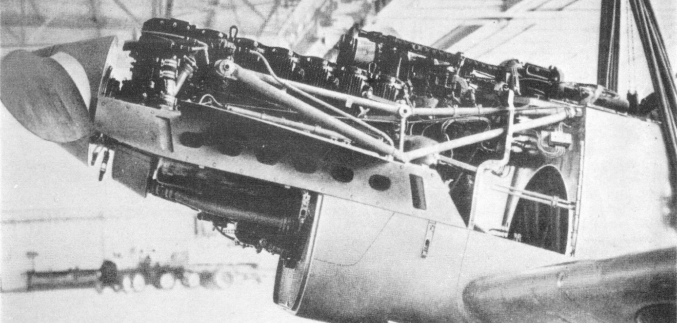
The Jumo 213E Kraftei. The entire assembly was bolted to the front of the fuselage and streamlined engine swaps. (ta152.de)
The engine had a bore and stroke of 150 mm and 165 mm, a compression ratio of 6.5:1, and a dry weight of 1040 kg. It differed from the standard model in that it had a slightly smaller bore, and the larger supercharger assembly and the associated intercooler added some 300 kg. It used B4 fuels which had a minimum octane rating of 87. The engine drove a constant speed 3.6 m VS 9 wooden propeller with a reduction gear of 1:2.40, and produced a maximum of 1753 PS (1729 hp) at sea level and 1260 PS (1242hp) at an altitude of 10.7 km. The oil header tank sat atop the front of the engine, and the coolant tank sat at the rear. On the Jumo 213A, these had a capacity of 55 and 115 liters respectively. The entire engine assembly was a Kraftei, or power-egg, consolidated unit, allowing the engine and its associated coolant systems to be easily removed or added to the aircraft.
Its radio and navigation systems included the FuG 16ZY ground control transceiver to allow it to be tracked and directed from ground based stations, a FuG 25A erstling IFF, and a FuG 125 radio direction finder for beacon homing. Some aircraft were also fitted with a K 23 level autopilot to reduce fatigue when flying the aircraft at high altitudes and in poor weather. The autopilot was accompanied with a heated windscreen and a FuG 125 Hermine radio navigation system as part of the R11 Rüstzustand equipment package.
Production of the Ta 152H
The Ta 152H was introduced in an environment where all quality control measures had already been cut down for every aspect of production. The lack of skilled labor and poor materials meant that building a reliable aircraft engine in Germany had become almost impossible by the spring of 1944. Slave labor and foreign, drafted workers, had become the base of the labor pool, as most of Germany’s factory workers had been drafted to fight, resulting in a sharp decrease in quality. This was not only a result of poor working conditions and the inexperience of the workers, but sabotage became widespread, especially among those pulled to work from concentration camps. Even more desperate measures began to be instituted in the summer of 1944, as the re-use of parts from salvaged aircraft became more commonplace, and engine test runs were ever more limited to conserve dwindling fuel supplies.
The first Ta 152H-0 was completed in November of 1944 after considerable delays due to several sets of blueprints being found to be inaccurate, and sets of construction jigs had been lost in France the previous summer. The first planes were sent to the Rechlin test center in December of 1944, while Focke Wulf considered how to accelerate production. While doing so, they were hobbled when the Jagerstab, which managed strategic fighter production, shifted more and more resources to jet fighters and older, established piston engined fighters. Ta 152H production standards continued to decline in the midst of the widespread economic collapse of Germany. Near the end of January 1945, it became almost impossible to build any more Ta 152H’s, as the decentralized production system began to collapse, the rail system became unusable, and the wing and fuselage production center at Pozen was overrun by the Allies.
By the war’s end, approximately 60 Ta 152H fighters had been completed at the Focke Wulf facility at Cottbus. The series suffered extreme quality control issues in service with JG 301, which included supercharger surging, and the failure of a propeller reduction unit, which resulted in the death of a pilot. In April of 1945, the plans were sold and shipped to Japan, where unsurprisingly, there was no new production of the aircraft.
Conclusion
The sole remaining Ta 152H is in storage at the Smithsonian Air and Space Museum, where it awaits restoration. (Smithsonian)
The Ta 152H is often seen as one of the great ‘what if’s’ of the Luftwaffe, but in reality, the aircraft was a good, rather than truly exceptional fighter. While on paper, the Ta 152H was to be an incredible aircraft at high altitude, it’s rushed development, and hasty introduction into service saw it fly without the combined GM-1:MW50 boost systems that it needed to achieve these feats, and in a rather regrettable state in terms of build quality. It stacked up well against many of the older aircraft in the theaters it fought in, like the Yak-9, Spitfire Mk IX, or the P-38L, and against its contemporary Allied rivals, it was a competitive fighter at high altitudes.
Specification:
Specification
Ta 152H-0
H-1
Engine
Junkers Jumo 213E
Junkers Jumo 213E
Engine Output
1753 PS, 2050 PS w/ MW50
1753 PS, 2050 PS w/ MW50
Empty Weight
4031 kg
Loaded Weight
4730 kg
5220 kg
Maximum Range
2000 km
Maximum Endurance
3.3 hrs
Maximum Speed [At altitude]
approximately 720 km/h [10.9 km]
760 km/h w/GM-1 [12.5 km]
Service Ceiling
15 km w/ GM-1 (estimated)
Armament
1×30 mm MK 108, 2×20 mm MG 151/20
same
Crew
1x pilot
same
Length
10.82 m
10.82 m
Wingspan
14.44 m
14.44 m
Wing Area
23.3 m^2
23.3 m^2
Height
3.38 m
3.38 m
Variants:
Ta 152H-0: Pre-production model, no wing fuel tanks, no MW 50 provisions, GM-1 capability but never cleared for operational use.
Ta 152H-0/R11: Poor weather pre-production series with level autopilot. Most pre-production aircraft were built in this configuration.
Ta 152H-1: Production model, wing fuel tanks, 85 liter GM-1 provisions but not supplied due to operational concerns. 70 liter MW 50 low pressure system installed. Fuel tankage increased from 595 liters to 995 liters with unprotected bag tanks in wings.
Ta 152H-1/R11: Poor weather model, autopilot. Most production aircraft were built in this configuration.
Ta 152H-1/R21: Equipped with Jumo 213EB intercooled engine, high pressure MW 50 system installed. Not operational.
Ta 152H-1/R31: Jumo 213EB, ballast kit to allow GM-1 use. No MW 50 and fuel capacity restricted. Not operational.
Ta 152H-2: FuG 15 radio set instead of FuG 16. Canceled in December 1944.
Ta 152H-2/R11: Bad Weather model.
Ta 152H-10: Photoreconnaissance model based on H-0.
Ta 152H-11: Photoreconnaissance model based on H-1.
Ta 152H-12: Photoreconnaissance model based on H-2.
Illustrations
The unique paint scheme of this aircraft was an identification measure, as the plane was largely unknown to German Flak and fighter crews. It was flown in this state to a conference.
Credits
Article written by Henry H.
Edited by Henry H. & Stan L.
Ported by Henry H.
Illustrated by Hansclaw
Sources:
Primary:
Aeroplane and Armament Experimental Establishment Boscombe Down Spitfire F. Mk. 21 LA.187 (Griffon 61) Climb and Level Speed Trials. 10 October 1945.
Einmotorige Jäger: Leistungsdaten, 1.10.44
Ersatzteil-Liste TA 152. Konstruktionsgruppe 7 Triebwerksanlage. Focke-Wulf Flugzeugbau G.M.B.H. Bremen.
Fighter Offensive Performance at Altitude Model P-47N-5RE Engine P&W R-2800-73 GP=45:1 Propeller-4 Blades- 13’0” DIA. (Curtis 836) War Emergency- 2800/2800 S.L. to Critical Altitude G.W.=13962 LBS. Republic Aviation Corporation. Farmingdale L.I., New York.
Horizontalgeschwindigkeit über der Flughöhe mit Sonderleistung. Leistungsvergleich Fw 190 – Ta 152. Focke-Wulfe Flugzeugbau G.M.B.H. 3.1.45
P-51B-15-NA 43-24777 (Packard Merlin V-1650-7) Performance Tests on P-38J, P-47D and P-51B Airplanes Tested with 44-1 Fuel.(GRADE 104/150). 15 May, 1944.
Smith F., M.A. and Brotherton J. Note on the performance in flight of the German jet-propelled aircraft Messerschmitt 262, Heinkel 162, and Arado 234. Royal Aircraft Establishment, Farnborough. October 1945.
Secondary:
Brown, Eric Melrose. Wings of the Luftwaffe. Hikoki, 2010.
Douglas, Calum E. Secret Horsepower Race: Second World War Fighter Aircraft Engine Development on the Western Front. TEMPEST, 2020.
Green, William. The Warplanes of the Third Reich. Doubleday & Company. 1970.
Harmann, Dietmar. Focke-Wulf Ta 152 the Story of the Luftwaffe’s Late-war, High-Altitude Fighter. Schiffer Military History. 1999.
Smith, J. & Creek, Eddie. Focke-Wulf Fw 190, Vol. 3: 1944-1945. Specialty Pr Pub & Wholesalers. 2015.
Smith, J. & Creek, Eddie. Me 262 Volume Two. Crecy Publishing. 2007.
Weal, John. Focke-Wulf Fw 190 Aces of the Western Front. Osprey Publishing. 1996.
Model 299G as it appeared in a microfilm document from a private collection on the B-17C. Note this is a recreation. (Bill Stanczak)
Introduction
There are very few planes in military and aviation history that have garnered as much attention or popularity as the Boeing B-17 “Flying Fortress”. The aircraft has been called by some “the best bomber of the Second World War”, although there are other contenders for that title. Opinions aside, one cannot dismiss the impact of the B-17 on military history and the evolution of strategic bombing. The development of the B-17 initially started with Boeing Model 299, often incorrectly called the Boeing XB-17 in various sources. Surprisingly, the B-17 was initially not selected for production, as the Model 299 prototype was destroyed in an accident and the US Army Air Corps’ limited budget did not allow for the purchase of the more expensive bomber. As this is such a popular aircraft, one would assume that quite a good portion of what there is to know about the plane and its development has already been researched, and documented. However, as is often the case, there are always discoveries waiting to be found, such as one particular obscure variant of the B-17, the Boeing Model 299G
To say that there is little to no information on this Model 299G would be quite an understatement as, aside from a few drawings, there is nothing that indicates why this aircraft was designed and what its exact purpose was. However, after studying the documents as well as consulting with several well-known aviation experts, it has become somewhat clear that what the Model 299G represents is not just an attempt to create a new and more effective variant of the B-17 based on the already in-production B-17B but, in fact, was a design concept that proved extremely influential in the design of the B-29 “Superfortress”.
Boeing: The American giant and a leader in aircraft design
The Boeing Company exemplifies the idea of rising from small beginnings. It was founded in 1916 on the shores of Lake Washington by a young timber baron by the name of William Boeing, who had an interest in aircraft. The first Boeing aircraft, a seaplane, took off from the shores of Lake Washington in January 1916. However, the company did not really take off until the 1920s and 30s, when Boeing achieved many great and public feats, including designing and building the first all-steel tube fuselage with its then-innovative arc welding process and even becoming one of the first companies to build dedicated mail aircraft. It was also during this time that Boeing would design and build some of its most legendary aircraft, such as the P-26 Peashooter, which, when introduced, was considered to be one of the fastest fighter aircraft in existence.
The company would gain even more fame and recognition with its construction of the Boeing Model 247 in the early 1930s, which allowed Boeing to dominate the early modern airliner market until the introduction of the Douglas DC-2 and the later Douglas DC-3. The Model 247 was considered to be extremely technologically advanced for the time and represented Boeing’s shift to all-metal aircraft construction. Boeing received even greater fame with its development and construction of the Boeing Model 299, which later became the B-17 Flying Fortress, an aircraft that was very well-liked by the top staff of the US Army Air Corps. The B-17 design would also later allow Boeing to create several other highly influential and popular designs based on the Model 299. These designs included civilian aircraft, such as the Boeing Model 307 Starliner and the famed Boeing Model 314 Clipper, which saw great fame while flying for Pan-American Airways in the late 1930s and even saw service as a Presidential transport aircraft for Franklin Delano Roosevelt. The Model 314, while externally quite different, used the same wing structure and design as the Model 299. The Model 299 design also brought forth various military variants which would see various uses, including transport aircraft in the case of the C-108 and VB-17. The Model 299’s development would ultimately culminate with the so-called “ultimate B-17”, the B-17G, which went on to become one of the most popular and well-known variants.
The Birth of Boeing’s big bombers
The development of the Boeing B-17 began in February of 1934, with a US Army Air Corps request for proposals for a new bomber with a range of 5000 miles (8046 kilometers) and a bomb load of at least 2000 pounds (907 kilograms). This request, designated “Project A”, was only a feasibility study for a production aircraft to these requirements. Even with it being a proposal, there was a chance the aircraft would be built, and Boeing put its best designers and engineers on the project and was clearly interested in developing the design. These designers and engineers soon found success, as they were able to successfully design and later build a very good aircraft. Initially, Boeing submitted the XBLR-1 (Experimental Bomber Long Range) for this program, which was later re-designated XB-15 upon its construction. Their competitor, Martin, also submitted a project, the XB-16, but that was later canceled before it actually left the drawing board, nor was a final design for it completed. Because of this, the XB-15 would remain the only bomber built in the XBLR program and was the largest until the Douglas XB-19 was built. The XB-15, while never serving as a bomber as intended, would eventually see service as a transport under the designation XC-105 and would serve until its retirement in 1944. Following its retirement, the aircraft would be partially dismantled and dumped in the so-called “Diabalo Dump”, where it remains to this day.
The Boeing Model 299 and the B-17
Boeing Model 299, often incorrectly called XB-17. (National Museum of the USAF)
In May of 1934, the US Army Air Corps announced a second competition, this time for a multi-engine bomber capable of carrying a ton of bombs, having a range of 2000 miles (3219 kilometers), and capable of flying at over 200 miles per hour (173 knots or 321 km/h). Unlike the previous competition, however, this aircraft would be built and brought into limited service, with a potential for full production. For this competition, Boeing decided to design and build what, in essence, was a scaled-down Model 294 (XB-15) under the designation Model B-299. The Model B-299 took many of the base features of the Model 294 and improved on them while scaling down the aircraft. In this regard, it was much like the 294, a twin-wing monoplane with four engines, but it also combined elements of Boeing’s successful Model 247 passenger aircraft. The prototype Model 299 first flew on 28 July 1935 and was very quick to impress the US Army Air Corps as well as the assembled press, with one reporter describing it as a “Flying Fortress”, and the US War Department describing it as an “Aerial Battle Cruiser”. On August 20, the Model 299 was flown to Wright Field, where it would spend the next two months being tested against the Martin 146 and the Douglas DB-1 (B-18 Bolo), where it eventually performed above and beyond the base requirements. The 299 would eventually get the US Army’s stamp of approval as well as an order for 65 YB-17s. However, on 30 October 1935, disaster struck and the Model 299 crashed and burned on takeoff. While the official cause was deemed to be a pilot error, as the pilot had forgotten, due to the lack of a checklist, to unlock the control surfaces (it was this accident that introduced checklists as standard equipment on aircraft), the US Army would cut the order to only 13 planes, designated Y1B-17, and instead ordered the production of 133 Douglas B-18 Bolos. The reason for this decision was twofold. While the destruction of the Model 299 did impact this decision, it was ultimately the US Army’s limited budget and their lack of funding that led them to ultimately choose the B-18 Bolo, as it was the only aircraft they could really afford a large number of. Despite this setback, the US Army was still enthusiastic about the design and allowed Boeing to submit another prototype for evaluation, which they did in the form of a modified Y1B-17 with more powerful engines and a crew of 6 instead of 7.
Boeing Model 299, note the distinctive nose with a small turret. (National Museum of the USAF).
The Boeing Y1B-17 did not differ too much from the original Model 299, however, some improvements were made, including switching the engines to the more powerful Pratt and Whitney R-1820s and changing the design of the landing gear arms. It was this prototype that ultimately won Boeing the contract and would go on into production as the Boeing B-17B.
The Model 299G: A modified B-17 or Something More?
When looking at the B-17’s lineage, one will notice that the very first mass-produced variant of the bomber was the Boeing B-17B or, as the Boeing Company knew it, the Model 299E (later changed to 299M). The B-17B followed a long line of prior limited or prototype variants, including the base Model 299, later Y1B-17, and Y1B-17A. The production run of the B-17B only ran for a total of 39 aircraft before it was switched to the B-17C (Model 299H). According to the documentation and the drawings found, the Model 299G was considered to be a very heavily modified B-17B which was re-engined with the Pratt and Whitney R-2180 Twin Hornets instead of the Pratt and Whitney R-1820-51 Cyclone. Beyond this, unfortunately, the drawings give very little information on this aircraft or really what exactly it was supposed to be. However, according to historians such as Mike Lavelle, this variant may be a link in the greater chain of designs that led to the Model 345, better known as the B-29 Superfortress.
The Design of the Model 299G
Boeing model 322 study, this one lacking the forward gun position but otherwise closely related to the 299G. (Lavell)
The Model 299G is unique compared to other B-17 variants and designs based on the B-17. It shares very little similarity with the Model 299 and Model 299M (B-17B) designs it is based on. Outside of the tail section and some other components, such as the general design of the wings, the rest of the aircraft is almost a completely different design from the B-17B on which it is based. Among the interesting features is the tricycle landing gear arrangement (one wheelset in the front, two on the wings). The aircraft also features a cockpit section very similar to that of the Boeing Model 307, completely eliminating the turtle deck. It shares a similar fuselage to the Stratoliner as well, as it was designed to test the feasibility of pressurization for use in bombers. Another major aspect that stands out about the aircraft is that it appears to have been both wider and longer than the B-17, with a slightly larger wingspan. Also featured were 4 defensive weapon blisters that almost seem like a cross of those on the early B-17s and those featured on the later PB4Y-2 “Privateer”. These were situated on the dorsal and ventral sections of the waist, with the ventral one just behind the wings and the dorsal one farther aft and closer to the tail.
Boeing Model 307 Stratoliner on display at the National Air and Space Museum Udvar Hazy Center. This is the sole preserved complete example. (Smithsonian)
The Model 299G also did not feature an astrodome. Rather, it featured what appears to have been a dedicated observation area above the cockpit. Perhaps the only major similarity it shared with the B-17 was that the 299G was a monoplane and, the wheels still receded into the engine nacelles. The design, as such, does not really seem to have been that of a B-17, bearing the most similarity to Boeing’s Model 307 Stratoliner, which was later adopted into US Army Air Force service as the C-75 Stratoliner. It also more clearly resembles Boeing’s later bomber designs, such as the Model 322, which eventually led to the development of the Model 345, better known as the B-29 Superfortress.
Conclusion
Boeing Model 316, a later design study possibly derived from the Model 299G. These two, and several others would go on to influence the further development of the B-17 and B-29. (Lavell)
While, ultimately, the Model 299G never left the drawing board, it certainly represents an interesting insight into the developmental history of Boeing’s large bomber projects. Based on conversations with several Aviation historians, it has been presented as a possibility that this Model 299G could also have been a very early attempt to design a sort of “Superbomber” that members of the so-called “Bomber Mafia”, including Jimmy Doolittle and General Hap Arnold, had been searching for. This conclusion would indeed make sense, as many of the features of the Model 299G do seem to correspond with later Boeing bomber designs. It has also been suggested that the Model 299G might have been a link in the greater developmental chain of the Boeing Model 345, which eventually saw service as the B-29 Superfortess. Some, however, have also suggested that this aircraft instead represented a link between Boeing Airliner development and their Military Aviation development. However, as of this writing, there is no concrete information or documentation that directly links the Model 299G to the Model 345, though it and other projects were part of the B-29 program’s design studies. Aside from general appearance, there is also really nothing concrete to link the 299G to airliner development either. What is undeniable though is that Model 299G does offer deeper insight into the continued development of the B-17 Flying Fortress and the influence, if indirect, it had on future projects.
Variants
Model 299G – The Boeing Model 299G was designed by Boeing and based on the Boeing B-17B. It never went past the design stage and was not selected for production.
Operators (Projected)
United States of America
US Army Air Corps (Presumed) – The Model 299G was designed by Boeing but never made it past the design stage.
Illustration
Credits
Article written by J. Manuel
Edited by Henry H. & Stan L.
Ported by Henry H.
Illustrated by Ed Jackson
Sources
Baugher, J. (1999, July 25). Retrieved from http://www.joebaugher.com/usaf_bombers/b17_1.html
The Boeing Company (2020, December 20). Retrieved from
http://www.boeing.com/history/#/legacy
Harris, S. M., & Angelucci, E. (1983). The Rand McNally Encyclopedia of military aircraft: 1914-1980. New York: Military Press.
Model 299 Crash. (2009, June 25). Retrieved from https://www.nationalmuseum.af.mil/Visit/Museum-Exhibits/Fact-Sheets/Display/Article/610002/model-299-crash/
Model 299 Press Release. (2009, June 25). Retrieved from https://www.nationalmuseum.af.mil/Visit/Museum-Exhibits/Fact-Sheets/Display/Article/610003/AFmuseum/
Lavelle, Mike. War on the Home Front: Building the B-29 Superfortress. Chester River Press, 2011.
Lavelle, Mike, and Matzelle, Liz. “Fwd Boeing 299G.” Received by Jonathan Manuel, 21 Nov. 2021
Simons, Graham M. The Boeing B-29 Superfortress: The Giant Bomber of World War Two and Korea. Pen Et Sword Aviation, 2012.
An artistic drawing of what this unusual aircraft might have looked like source: www.nevingtonwarmuseum.com
The German military industries during the Second World War are often seen as highly developed, and producing highly sophisticated, superior weaponry to that used by the Allies. The reality is quite different, as they began to implement the mass use of slave labor and were chronically short of several key resources. Regardless, bright engineering minds and desperation led to the introduction of a series of new technologies, some being the first of their kind. The German aviation industry was credited with creating some advanced and innovative, but ultimately scarce aircraft designs such as the Me 262 jet fighter. With this reputation, many theories on German hyper-advanced, secretive aircraft projects began to spread after the war. Among them, was the theory that they had created a series of supersonic, flying saucers.
The Myth of German Technological Superiority
In the decades after the Second World War ended, in media and popular culture, German military technology and industry were often presented as significantly superior to the Allies. This is perhaps the most obvious when mentioning the German Wunderwaffe (Eng. wonder-weapon). These weapons ranged from flying bombs, ballistic missiles, jet engines, and super-heavy tanks. In essence, from the German perspective, the Wunderwaffe presented any weapon that would help them turn the tide of the war. Probably the best examples that were used in greater numbers were the V-2 rockets and the Me 262 jet fighter. In the case of the V-2, these were used en masse to bomb targets in Great Britain and continental Europe. Descending at a speed of nearly 6000 km/h, they could not be tracked and struck without warning. The Me 262 was able to achieve speed far superior to that of ordinary piston-powered aircraft., and with its armament of four 3 cm cannons, it could easily take down heavy Allied bombers.
Before we go any further we must discuss the history and truthfulness of these wonder weapons and their origin. It is important to point out that the German war industry prior to and during the war struggled with numerous industrial shortcomings. It was unable to produce enough quantities of weapons and materiel to satisfy the German Army’s demands. This can be best seen in the pre-war tank production when during the invasion of Poland, only a limited number of modern Panzer III and IV were available. The lack of anything better forced the German armored formation to rely on the weaker Panzer I and II tanks. The effective heavy tanks, such as Tigers, due to their complexity and price, were built in limited numbers. Even the Panther, of which some 6,000 were built, which was much cheaper and easier to build, could never be produced in such numbers to fully replace older designs. The Army itself, while generally portrayed to be highly motorized, was actually heavily dependent on horses for the transportation of artillery and supplies.
Regarding the term Wunderwaffe, it is almost entirely associated with German propaganda. The term was more actively used when the war began to turn bad for the Germans, especially after defeats like the one at Stalingrad. In theory, any weapon or vehicle could be categorized as a Wunderwaffe. Ranging from an assault rifle to a jet-powered aircraft. Some were just paper projects or simple proposals that were intended to enter production but they actually never did.
Now the question would be were these weapons truly superior to the Allied ones? A simple answer is no, but every single of these Wunderwaffe had pros and cons, so making a simple conclusion about their effectiveness and use would revive extensive research and work that is beyond this article. But we can briefly consider the effectiveness of the two previously mentioned weapons systems, the V-2 and the Me 262. While the V-2 was quite advanced for its day, it was plagued with many problems. The reliability of the rockets was not guaranteed with some of them exploding during take-offs. Precision was their weakest point, and by late 1944, when they were used en mass, the Germans simply lacked the means to observe their effectiveness against targets in Great Britain and could not correct the aim of the rockets. The Me 262 was also far from perfect, given the technological novelty of many of its components, it too suffered from poor reliability. Both weapons were also introduced too late to have any real impact on the war.
The first mass-produced jet fighter in the world was the Me 262. Source: Wiki
The Germans lost the war, which obviously showed that the concept of the Wunderwaffe was just a desperate attempt to increase the morale of its people and to fight the ever-increasing fear of a possible defeat. But despite it, these weapons continued to tickle the imagination in modern-day culture. To some extent, some mysteries would emerge after the war, that were either fabricated or were to some extent real. The probably best-known, and most infamous is the German flying disc project which employed the unusual circular wing design.
A Brief History of Circular Wing Design
While the circular wing design may be seen often wrongly connected to the unidentified flying object its actual origin is more earthly in nature and goes way back to the 18th century. One of the first recorded proposals for using a circular wing design to create a flying contraption was presented by Swedish scientist and philosopher Emanuel Swedenborg. He published his work in a scientific journal in 1716, but his proposal ultimately led nowhere. Nearly two centuries later in 1871 when French inventor Alphonse Penaur tested his own flying model. Encouraged by this success in the following years he began working on a new aircraft design that was to have elliptical wings and be powered by two smaller steam engines. But he committed suicide in 1880 and never fully implemented this new project. In the 1910s a wealthy weaver, Cedric Lee and his friend George. T. Richards began working on a circular wing glider. After a series of flight tests, they noticed that the glider had a good overall flying performance. Inspired by this success, they hired an engineer, James Radley, to help them build their new propeller-driven circular-wing aircraft in 1913. This aircraft also performed well during its test flight, but during the landing, the engine stopped and the aircraft crashed. While the pilot was unharmed the aircraft was a complete loss. Both Cedric Lee and George. T. Richards continued working on improving their design, but after a few more crash landings, they gave up on their project. In the 1940s, the American Army and Navy experimented with using a few different semi-disc wing designs These were the Boeing B.390 and the XF5U-1. While boths were surely interesting aircraft, their overall design proved to be a failure and none would be accepted for service.
Cedric Lee and George. T. Richards incomplete experimental circular-wing aircraft. Source: B.Rose and T. Buttler Secret project Flying Saucer AircraftThe Boeing B.390 design, while being a much simpler design than the XF5U-1, proved to be an unsuccessful design. Source: B.Rose and T. Buttler Secret project Flying Saucer Aircraft
The Flying Disc Project
The history of German flying disc projects is rather poorly documented, and in many cases, outright fabricated. They were allegedly related to German attempts to develop a vertical take-off and landing (VTOL) aircraft. It is surrounded by a veil of secrecy, and quackery, and probably that is the main reason why it is often connected to mythical or even supernatural origins. It is worth mentioning that the sources regarding these developments are quite unreliable, as they are mostly based on stories told by eyewitnesses and individuals. The reliability of these eyewitnesses and individuals should be taken with a great grain of salt. We must take into account that many of the written sources were made decades after the alleged events occurred. Another vital point to consider is the reliability of the main individuals that were allegedly involved in such projects. One such person was Rudolph Schriever, who after the war, gave an account of his reputed involvement in the development of a secret flying disc aircraft.
According to his story, the German Reichsluftfahrtministerium RLM (Ministry of Aviation) appointed a young aircraft design engineer and pilot, Rudolph Schriever, to work at the Heinkel-Rostock design office. In reality, he had no verifiable claims to German military service, relating to aviation or otherwise, and his only known employment was for the US Army as a truck driver after the war. It’s also not quite clear, but in some sources there is a mention of a certain Otto Habermohl, supposedly also involved from the start. Not to be beaten out by Schriever, there is not only any evidence for his credentials, but he doesn’t seem to have existed at all.
At that time, different engineers wanted to solve the issue of reducing the space needed to launch and recover aircraft. One solution was to launch an aircraft directly, and vertically into the sky. In this case, such aircraft would not need a long runway and instead could take to the sky from a single launching point. But this concept, while tested over the years, was never successfully implemented during the war.
Schriever claims to have approached this problem with a somewhat unusual solution. He made plans using a disc-shaped aircraft powered by jet engines using the so-called Coanda effect. This effect was named after the Romanian Henri Marie Coanda, an aerodynamic engineer. He discovered that when using a jet stream that is applied tangentially against a convex surface it creates a lift force that could be further increased by circulation. Schiriever claimed to have presented his idea to Ernst Heinkel, who was said to have liked the concept. This supposedly led to the start of work on a small prototype. He claims that after some work, the prototype was completed in early 1941. This prototype received the simple V1 designation without any prefix for the aircraft type. This should not be confused with the V1 flying bomb, as the V stands for Versuchs (experimental or trial model) which was quite commonly used by the Germans especially in the aviation industry to describe experimental or pre-production models. This prototype supposedly consisted of a disc-shaped wing design powered by an electrical rotary fan, no power source is given.
In 1942, this prototype was allegedly flight tested. No precise information about its overall performance exists. The assembly of this prototype named V2 was said to have begun in nearly 1943. By that point, Schriever claimed that some design work was moved from Germany to occupied Czechoslovakia. Škoda factories near Prague are assumed to have provided assistance to this project, though he did not specify in his testimony. A few other companies were also mentioned to be to some extent involved in this project, this includes Junkers, Wilhelm Gustloff, and Kieler Leichtbau. The fate of the V2 prototype is not clear.
The testing of the Schriever flying disc was supposedly observed by a group of some 25 eyewitnesses from the Flight school which was stationed near this airfield. One of these eyewitnesses gave testimony to a German aeronautical magazine Flugzeug in 1987. The truth of these claims cannot be completely verified with certainty. If we consider the fact that more than 40 years have passed since this incident to the moment they gave the interview. They reportedly saw a strange disc-shaped aircraft. This aircraft was described as disc-shaped with an estimated diameter between 5 to 6 m with the height of an average man. They also reported that it had an aluminum color. And that while being on the ground held in position by four landing gear legs. It managed to reach a flight of around 300 m of distance at 1 m of height. In the event the witness was not being intentionally misleading, it is likely they saw a helicopter being tested, several designs of which were researched and built during the war.
This piece of equipment is often mentioned to be the Rudolph Schriever demonstrator for the whole concept.It shares a notable resemblance to a torque converter. Source: B.Rose and T. Buttler Secret project Flying Saucer Aircraft
Name of the project
Beside the names given to the prototypes, this whole project appears to not have received any official designation, which was somewhat odd. It is often simply referred to as the Heinkel-BMW or by its name of the inventor Schriever, or even as the Schriever-Habermohl flying disc. Also sometimes it is also referred to as Flugkreisel (Flying top). This article will use the Heinkel-BMW flying disc designation for the sake of simplicity only.
Further Work
By 1944, the whole team that worked on this project was supposedly moved to Czechoslovakia. The entire personnel were not stationed at one facility but instead relocated to various small cities in that occupied country. Allegedly, this was done to avoid any of them being killed in the Allied bombing raids. The main base of operation was said to be the Praha-Kbely Airfield. According to Schriever, by this time, other aircraft design engineers began joining the program. One of them was SS Lieutenant Helmut Zborowski who was then appointed commander of this base. Given his position, Helmut would be most likely directly involved in the project. Others included Dr. Richard Miethe who may have been involved in the German rocket development. He may have been involved in the Peenemunde rocket research center, but his work there was never verified and so far no connection has been proven. Lastly, there was Klaus Habermohl and surprisingly an Italian, Dr. Giuseppe Belluzzo, who specialized in the work of turbines. The involvement of these two in the supposed project is unclear. Dr. Giuseppe Belluzzo claimed after the war that he was involved in the disc-shaped aircraft project but there is no proof of this. Klaus Habermohl is another strange person that allegedly worked on this project. What is bizarre is that no actual proof was ever found that this was a real person that existed. Lastly, the role of Joseph Andreas Epp, who was an engineer, was a supposed consultant to the Heinkel-BMW flying disc program. After the war, he claimed to have greatly influenced the German disc-shaped aircraft project, but if this is true, or was just an attempt to gain fame are unknown, the latter option seems more possible.
Schierver claimed that, together this team decided to proceed and built a third,even larger aircraft. The necessary component for the aircraft was to be supplied by Heinkel while Bayerische Motoren Werke AG – BMW was to have been responsible for providing the necessary engines. During the construction of the V3 prototype, one member of the team proposed using an experimental radial flow gas turbine engine which was adopted. The V3 was said to have been completed in the autumn of 1944. It was said to be almost double the size of the previous prototype with a diameter ranging from 12.2 to 15.1 m. No specific model of jet engine was mentioned. Supposedly, this aircraft was capable of achieving subsonic speed and could take off vertically.
Alleged drawing of the V3 prototype, note there are a few slightly different drawings of this alleged prototype. Source: www.nevingtonwarmuseum.com
As the war was by this point obviously lost, the Germans tried to delay the inevitable, and out of desperation, the SS became more involved in Wunderwaffe projects. This flying disc was said to be one of them, with their supposed involvement helping to add another layer of esotericism. Supposedly, soon the new V7 prototype was under construction. The fate of the V4, V5, and V6 prototypes is unknown. The last prototype, the V7 was reportedly designed to be larger than its predecessor by having a diameter of 18.3 to 21.3 m. This prototype was to be powered by gas turbine engines, from the start. At some point the work on the prototype was supposedly taken over by Richard Miethe.
Technical characteristics
Given the general obscurity and poor source materials, the precise construction of this bizarre aircraft is unknown. The available information should be regarded as illegitimate as it is technically incorrect, extremely inconsistent, and often fantastical.
The aircraft itself was envisioned as a circular-rotary wing design likely made of metal and powered by several smaller jet engines. It consisted of a centrally positioned crew cabin, which was surrounded by a large rotary wing assembly, resembling a huge fan. These were surrounded by a huge likely metal ring. What holds this ring in place is not clear according to a few drawings of it that exist.
The V7 had a diameter of 18.3 to 21.3 m. To provide stability it is often suggested that this aircraft received a stabilizing fin added close to the central cockpit. The central cockpit appears to be hemispherical and was fully glazed, providing the crew with a good upper all-around view. The lower view would be greatly restricted by the large rotary wing and present extreme difficulty in landing. How they would resolve this issue is not clear. It is possible that at the bottom of the cockpit, additional windows were to have been added. The crew consisted of two to three crew members whose roles were not specified.
Beneath the large rotary wings, at least four jet engines were to be used to power the whole assembly. These provided lift during take-off and landing. Allegedly, horizontal flight could be achieved by adding additional engines possibly connected to the lower part of the cockpit unit. Several different possibilities could have been used for this project. Ranging from Jumo 004, Jumo 211/b, BMW 003 engines, Walter HWK109 rocket engine, or the Argus pulsejet. Its alleged maximum speed achieved was 1,200 km/h or up to 2,000 km/h at a height of 12,400 m. Given its nature, and that none of the engines would have sufficient performance for supersonic flight, both numbers seem unrealistic, to say the least. Even in Rudolph Schriever’s own testimony after the war, he claimed that the prototype only managed to achieve some basic flights. There is no record that any kind of armament was tested on this aircraft.
The Fate of the Project
Like most parts of this aircraft, its final fate is unknown. Hard to verify, and often absurd claims, mention that it climbed to heights of 12.200 m or managed to reach supersonic speed. Given that it was supposedly in its early development phase when the previously mentioned test flight was made, it is dubious that such a flight was possible even with all of the other issues.
The V7 was said to have been destroyed by the Germans to prevent its capture. Or the Germans failed in this and the Soviets managed to capture it, with no evidence existing in either case. There was also said to be a V8 prototype that was under construction by the war’s end. Another interesting but unconfirmed information is that some members of the team who worked on this flying disc including Richard Miethe actually managed to surrender to the Western Allies. This seems unlikely and was possibly fabricated by Miethe, who was known to have been involved in some different conspiracy theories, so his background is also not verifiable.
The alleged photograph was taken by Joseph Andreas Epp while he was driving toward the Prag airport in (possibly August) 1944. The part of the picture to the right is the same photograph that just increased in size and focused on the aircraft itself. Source: H. Stevens, Hitler Flying Saucers
Ironically, the Germans actually managed to develop and built in small series a rocket-propelled VTOL aircraft, the Ba 349. While quite an unusual design, it was a real, and more practical aircraft in contrast to fictitious flying disc projects. By the time it was flight tested in March 1945, it proved to be a failure.
The experimental and unusual rocked-powered Ba 349 Source: Wiki
Production
After the war, Joseph Andreas Epp claimed that at least 15 various prototypes were built and tested by the Germans. This number also includes another similar project that runs parallel to the alleged Heinkel-BMW project.
V1 – Small prototype model
V2 – Second prototype whose fate is unknown
V3 – Tested in late 1944
V4-6 – Possibly paper projects
V7 – Larger fully operational prototype
V8 – Alleged improved V7 prototype
Is the whole story actually True?
Not surprisingly the entire story about Rudolph Schriever’s work is in all likelihood, a complete fabrication. Author, G. Rendall (UFOs Before Roswell) gives a quite detailed account of the Schriever’s involvement, or better said, lack thereof in the German flying disc program.
The connection between Schriever and the Luftwaffe is not clear. While he is often described as having the title Flugkapitan (Flight Captain) this was not an official military rank but instead an honorary title given to civilian test pilots for their service. This usually includes testing a prototype aircraft and testing newly built planes. Schriever, allegedly thanks to his idea of a flying disc, and pilot skill was said to be summoned to Heinkel. In reality, there is no evidence to support this, neither him being an engineer nor a test pilot. His first public appearance and general mention of his flying disc project occurred when he gave an interview to the Der Spiegel news magazine on the 30th of March 1950.
Schriever may have been influenced to come up with his story by the Italian post-war flying disc stories. In the late 1940s Italian engineers showed great interest in designing similar aircraft. One engineer Francesco de Beaumont proposed a disk-shaped aircraft design powered by four jet engines. Another engineer Giuseppe Belluzzo in his own story given to the magazine Il Giornale d’Italia, was he mentioned Italian and German flying disc development.
Francesco de Beaumont proposed a disk-shaped aircraft proposal. Source: B.Rose and T. Buttler Secret project Flying Saucer AircraftA drawing of the Rudolph Schriever flying disc was published in the German newspaper Der Spiegel in March 1950 Source: H. Stevens, Hitler Flying Saucers
In any case, according to Schriever’s interview, he allegedly became involved in the flying disc program in 1942. Quite interesting is the fact that according to Schriever’s own words, this aircraft was successfully flight-tested. He continued to work on this project up to the end of the war when he had to flee with the whole documentation and plans. He set up a small workshop and the documents were stored there. In 1948 he claimed that they had been stolen by an unspecified foreign agency and never found. Despite claiming to be involved in the secret flying disc program as an engineer, Schriever after the war worked as a simple truck driver. As there is no proof of the Heinkel-BMW flying disc, the whole story seems like a fabrication invented by Schriever. As in his later interview, he claimed to be involved in other projects; it is likely that he was seeking attention possibly from the Allies or simply just bored during a time when Germany was undergoing a slow, painful recovery. To add to the likelihood of the latter, at that time German engineers were highly in demand by the Allies and the Soviets. The US army even organized special operations to bring many German scientists to America, yet Schriver’s claims of the disc aircraft were completely ignored. If being recruited was Schriever’s intention, he failed in that regard. In the end, Schriever’s story ended with his death in 1953, as reported by the German Newspaper, Deutsche Illustrierte
The Real German Circular-wing aircraft
As it is often the case, the reality is often quite disappointing for those who believe in the extraterrestrial and esoteric origins of German flying source projects. Likely the only circular-wing design that reached some operational level was the Arthur Sack Sack AS-6. While even this aircraft had a rather obscure history, it is known that one prototype was completed and tested. Given that this was mostly a one-man project built using salvaged components, it should not come as a surprise that it led nowhere. During testing, the aircraft failed to take off and after a number of improvements, attempts to fly the aircraft were eventually discarded. The only prototype would be destroyed in an Allied bombing raid. The Horten Ho 229 could technically also be classified as a flying disc aircraft, though by any technical definition, it is a flying wing. Despite some effort put into its development, it remained at the prototype stage. There were many other projects but few went beyond a mock-up stage.
While Arthur Sack’s work was never implemented in mass production, his unusual design was often mistakenly taken as some advanced and secret German World War II project, which ironically, it never was. Source: all-aero.comThe unusual Sack AS-6 circular-wing aircraft. Source: alkeeins.blogspot.comFew prototypes of the unusual Horten Ho 229 were built and tested during the end of the war. Source: www.ww2-weapons.comFocke-Wulf wooden mock-up of a VTOL aircraft that has some resemblance with a flying disc. Source: B.Rose and T. Buttler Secret project Flying Saucer Aircraft
Conclusion
Based on the few available information what conclusion could be made regarding this unusual design? Given its supposed secrecy and some element of Wunderwaffe allure, there is no doubt that the project is by all indications, fictional. Given the fact that the Germans allegedly spent years developing such aircraft but did not advance beyond the prototype stage, probably an indicator that the whole concept was likely flawed if it existed in the first place.
In the case of Rudolph Schriever’s work, it is quite certain that his entire involvement in such design was purely made-up after the war. Why he would do so is unclear. It is possible that he tried to get the attention of the Allies. In this regard, he failed, as the Allies probably saw,if they ever bothered in the first place, that the whole story was fake and invented from the start. It is much more likely that Rudolph Schriever simply wanted to do a publicity stunt, as he was probably extremely bored being a truck driver in post-war Germany. In the end, it’s likely that Rudolph Schriever never suspected that his story would have gone so far, being propelled by the flying saucer craze of the 1950s.
Alleged Heinkel-BMW V7 Specifications
Wingspans
18.3 to 21.3 m
Engine
Multiple unspecified jet engines
Maximum Speed
1.200 to 2.000 km/h / 745 to 1240 mph
Maximum Service Ceiling
12.400 m
Crew
2 to 3
Armament
None
Illustration
Artist impersonation of the Heinkel-BMW Flying disc
Credits
Article written by Marko P.
Edited by Henry H.
Ported by Henry H.
Illustrated by Medicman 11
Source:
D. Nesić (2008) Naoružanje Drugog Svetsko Rata-Nemačka. Beograd.
R. Ford (2000) German Secret Weapons of WWII, MBI
B.Rose and T. Buttler (2006) Secret project Flying Saucer Aircraft, Midland
J. R. Smith and A. L. Kay (1972) German Aircraft of the WW2, Putnam
H. Stevens, Hitler Flying Saucers. Adventures Unlimited Press
M. Fitzgerald (2018) Hitler Secret Weapons Of Mass Destruction, Arcturus
G. Rendall (2021) UfOs Before Roswell, Graeme Rendall
In the years prior to the Second World War, in Europe, there was significant interest in the development of aircraft intended to be used for breaking various world records. International competitions and exhibitions of new aircraft technology were quite common in this period. While at first glance this may seem like a hobby or sports event, in reality, these were often used for propaganda purposes to glorify a nation’s own aviation industry as superior to those of other countries. Achieving the greatest possible speed was often regarded as a clear measure of engineering supremacy over other countries. Germany was one of these, which took up the task in the late 1930s to achieve the greatest possible speed. They successfully achieved with the Me 209, an excellent record-setter, but completely unsuited for military use.
History of the Me 209
Due to restrictions imposed by the Western Allies, the Germans were partially limited from researching certain aircraft technologies. This did not stop them, however, as German aviation enthusiasts and aircraft manufacturers found numerous ways to bypass these restrictions. In the early 1930s the German aircraft industry worked at full capacity in order to increase the production of ever-needed new aircraft designs, but also introduced a series of new technologies. When the Nazis came to power in 1933, huge investments were made in order to build one of the most modern air forces in the world. Thanks to these resources, the Germans introduced a series of excellent aircraft designs that would dominate the skies over Europe in the first years of the war.
Some of these aircraft were specially modified so that they could be reused as propaganda tools. Their purpose was to achieve as many world records as possible. On the other hand, these were never actually accepted for service. One aircraft developed by Heinkel, the He 100, managed to achieve great success by reaching a speed of 764 km/h. However, this was not enough in the minds of the leading officials of the Reichsluftfahrtministerium – RLM ( German Air Ministry) who wanted something more imposing to show to the world. Adolf Hitler himself wanted to show off the superiority of the German aviation industry. So to win worldwide prestige in aviation, in 1937 Messerschmitt was instructed by the RLM to begin developing an experimental aircraft that set the world speed record. Given its specialized nature as a high-speed record-breaker, Messerschmitt received production orders for three prototype aircraft.
Willy Messerschmitt and his team of engineers began working on such a project, codenamed P.1059 in the early stage of development, soon after the requisite was made and the first working prototype was now under the designation Me 209 V1 (D-INJR).
The Me 209 mock-up in its early development stage. Most evident is the unusually rear-positioned pilot cockpit. Source: ww2fighters.e-monsite.com
The Prototype Development
The Me 209V1 prototype made its maiden flight at the start of August 1938. This flight was rather short at only 7 minutes. It was flown by the Messerschmitt chief engineer J. H. Wurster who was also a pilot. It was initially planned to use the experimental DB 601ARJ engine. As it was not yet available, a more orthodox 1,100 hp DB 601A engine was used instead. Almost from the start, the Me 209V1 was shown to be a troublesome design. Numerous issues were detected during flight testing. Some of these included the aircraft’s tendency to abruptly dive in mid-flight, the controls being heavy and hard to work with either in the air or on the ground, cockpit ventilation was poor, engine overheating problems were evident due to insufficient cooling, and cockpit visibility was quite limited. During landings, the Me 209 showed that it had a high sinking rate which usually led to a harsh landing, potentially causing damage to the landing gear. Despite all of this, which would in other circumstances lead to a sure cancellation of the project, the RLM officials urged that the Me 209 development should go on.
The side view of the Me 209V1 prototype. Interestingly the Messerschmitt workers did not even border apply any paint job to it. The natural aluminum color is quite evident in this photograph.
The second prototype Me 209 V2 (D-IWAH) was completed in early 1939. It was flight-tested for the first time on the 8th of February 1939. At that time Wurster gave up his position as the Messerschmitt test pilot to Fritz Wendel. On the 4th of April, there was an accident where this aircraft would be lost. After a short flight, the pilot Fritz Wendel was preparing for a landing approach on Haunstetten airfield. Suddenly, and without warning, the engine stopped working and the aircraft rapidly lost altitude. In another version of this event, the engine stopped working shortly after take-off. Regardless of which event was true, the aircraft was lost but surprisingly the pilot Fritz Wendel survived the forced landing without injury.
The Me 209V2 aircraft during its construction. While it was to be used for breaking the world record, its early demise meant the V1 had to be used instead. Source: ww2fighters.e-monsite.com
In the meantime, with the loss of the V2 aircraft, the testing continued using the first prototype which was finally equipped with the DB 601ARJ engine. This engine was rated for 1800 PS on take-off, with its emergency power setting reaching 2,465 PS.
A New World Record
As the V2 was lost and the other two prototypes were still under construction, it was devised to use the V1 aircraft for the anticipated world record flight. On the 26th of April 1939, while piloted by Fritz Wendel, the Me 209V1 reached a phenomenal speed of 755 km/h. It would take nearly 30 years before the record was beaten by a modified American Grumman F8F-2 in 1969.
German Minister of Propaganda Joseph Goebbels was quick to exploit this successful flight. Goebbels propaganda machine soon published this news as a great success of the German aviation industry. To hide the experimental nature of the Me 209, in propaganda news it was renamed Bf 109R. This was also done to deceive the general foreign public that this was an actual operational fighter. Shortly after that, all further work on beating the speed record was strictly forbidden. Following this success, Me 209 V3 (D-IVFP) was completed and flight-tested in May 1939. Its flight career would end shortly as its frame was mostly used for various testing and experimentation duties.
Technical Characteristics
The Me 209 was a low-wing, all-metal, single-seat, experimental record-breaking aircraft. Unfortunately due to its experimental nature, not much is mentioned about its precise construction in the sources.
The fuselage and the wings were made of a metal frame covered in aluminum sheets. The rear tail unit had an unusual design with the rudder being greatly enlarged. This was done to help the aircraft design cope with propeller torque.
The Me 209 landing gear consisted of two landing gear units that retracted outward towards the wings. The Me 209 used a more common type of landing gear that retracted inward to the wings. To the rear, a sliding skid was placed at the bottom part of the large tail fin. The skid was connected with a spring to the tail unit and could be completely retracted to reduce the drag.
The cockpit was placed quite to the rear of the aircraft fuselage. This design had a huge flaw, as it severely restricted the pilot’s front view. The canopy of this cockpit opens outwards to the right. It was likely taken directly from Messerschmitt’s early design of the Bf 109. In an emergency, the canopy could be jettisoned.
The Me 209 was to be powered by the DB 601ARJ engine, a twelve-cylinder, liquid-cooled V-12 engine. This engine used a Messerschmitt P8 three-bladed propeller. The engine cooling system was rather unusual. As the Messerschmitt engineer wanted to avoid using a standard radiator to avoid unnecessary drag, they came up with a new design. The engine was cooled with water, which was nothing unusual, but the way the water itself was cooled was quite a new and complicated process. The hot water steam from the engine was redistributed to the wings through pipes. Once in the wings, through a series of specially designed openings, the hot water stream would be condensed back to a liquid state. The cooled water would then be brought back to the engine, where the process would be repeated again and again. The negative side of this system was the constant loss of water due to evaporation, which depending on the conditions like speed may differ widely from 4 to 7 liters per minute. Due to this huge loss in a short amount of time, the aircraft had to be equipped with a 200 (or 450) liter water container. With this water load capacity, the Me 209 had an endurance time of only 35 minutes.
The Me 209 cockpit canopy opens outwards to the right. This design had a flaw as it could not be left open during takeoff or landing. In an emergency, the canopy could be jettisoned. Source: ww2fighters.e-monsite.comThe Me 209 was to be powered DB 601ARJ engine which used a Messerschmitt P8 three-bladed propeller Source: aviadejavu.ruThe rear view of the Me 209V1, where the enlarged vertical stabilizer could be seen. Its purpose was to help the aircraft cope with propeller torque. Source: ww2fighters.e-monsite.com
Attempt To Develop a Combat Version of Me 209
In May 1939 the Me 209 V4 (D-IRND) was flight tested. While the previous prototypes were to be used for beating international world records, the V4 was an attempt to adopt the Me 209 for potential military use. It was not requested by the RLM but instead a Messerschmitt private venture.
This prototype would receive a military code CE-BW in 1940. Its design was modified to include new and enlarged wings. The racing engine was replaced with a military model, the 1,100 hp DB 601. Due to the limitations of the wing-mounted cooling system, it had to be replaced with conventional radiators, which were changed several times in the Me209 V4’s development. The wing design was also changed as it was somewhat larger and longer than that used on the original Me 209. These were also provided with an automatic leading-edge slat.
In addition to its new purpose, it was to be equipped with offensive armament. The sources disagree on its precise armament. According to, D. Myhra (Messerschmitt Me 209V1) it consisted of two 7.92 mm MG 17 machine guns placed above the engine, a 2 cm cannon that would fire through the propeller shaft, and two 3 cm Mk 108 cannons to be installed in the wings. The potential use of this wing-mounted armament is quite questionable for a few reasons. The installation of such a cannon would not be possible given the limited room inside the wings. In addition, the MK 108 would be introduced to service in the later stages of the war, years after the Me 209 V4 was tested.
Authors J. R. Smith and A. L. Kay (German Aircraft of the WW2) on the other hand mentioned that the wing armament was to consist of two MG 17 machine guns, but this had to be abandoned as there was no room in the wings for them.
During testing of the much modified Me 209V4 it was shown to have weaker general flight performance than the already produced Bf 109. Attempts to further improve it by installing a stronger engine failed, as the Me 209 was still underpowered as its airframe was designed around a phenomenally powerful engine. Despite all this work the Me 209V4 was simply not suited for use as a fighter and thus the project had to be abandoned.
The Me 209V4 was a failed attempt to introduce to service a new and improved fighter aircraft that would potentially replace the Bf 109. It was not requested by the RLM but was instead Messerschmitt’s own private venture. Source: www.luftwaffephotos.com
The Fate of the Me 209 prototypes
Following the completion of its original goal, the Me 209V1 aircraft was given to the Berlin Air Museum in April 1940. While initially the Messerschmitt workers simply kept the natural aluminum color for the Me 209. This was not appropriate for an exhibit; it would be repainted in dark blue with its code painted to its fuselage sides. Interestingly during its brief service, the Me 209 was often nicknamed by its crew as Fliegend Eber (Eng. flight boar).
The Me 209V1 just prior to being allocated to the Berlin Air Museum in April 1940. The pilot is Fritz Wendler, and next to him it is Willy Messerschmitt. Source: ww2fighters.e-monsite.coml
In 1943 the Berlin Air Museum was hit during an Allied bombing raid and many aircraft were lost. The Me 209V1 was damaged but its fuselage was left relatively intact. It and other exhibits were moved to Poland for safekeeping, where it was simply forgotten. It was not until 1967 that Norman Wiltshire from the International Association of Aviation Historians actually discovered its remains during his visit to the Polish Air Museum in Krakow. The preserved Me 209V1 fuselage is still located at the Polish Museum, despite many attempts by the Germans to buy it back. The Me 209V3 was completely destroyed in one of many Allied bombing raids of Germany, while the V4 was scrapped at the end of 1943.
Me 209 fuselage at the Polish Aviation museum in Krakow, Poland Source: www.wikiwand.com
Japanese Interest
Despite being obvious from the start that the Me 209 would not enter production, a Japanese attaché showed interest in the project. In 1943 he approached the RLM officials with a request for technical data and that one aircraft to be shipped to Japan. In the end, it appears that nothing came of this and no Me 209 was ever sent to Japan.
An Me 209 but not a Me 209
As the war progressed, Messerschmitt engineers were trying to design a new piston-powered aircraft that would replace the Bf 109. That would initially lead to the creation of the Me 309 which proved to be a failure, and in 1943 a new project was initiated named Me 209. This project, besides having the same name, had nothing to do with the original Me 209 record holding aircraft. The first prototype of this new design was designated Me 209V5 in order to avoid confusion with the previous Me 209 aircraft design. It used many components of the already existing Bf 109G and had a fairly sound design. The few prototypes built would receive the designation Me 209A (sometimes referred to as Me 209II) designation. Despite their improved performance over the Bf 109G, the Luftwaffe opted for the Fw 190D instead, which proved to be a better use of the Junkers Jumo 213 engine.
The Me 209A, besides the name, had nothing in common with the first Me 209 aircraft. Source: www.luftwaffephotos.com
Production
Production of the Me 209 was carried out by Messerschmitt at Ausburg. The RLM ordered three prototypes to be built which were completed by 1938. The fourth prototype was Messerschmitt’s own project which ultimately proved to be a failure.
Production Versions
Me 209 V1 – First prototype was successfully managed to break the world speed record.
Me 209 V2 – Lost in a landing accident
Me 209 V3 – Third prototype that did see limited use
Me 209 V4 – This prototype was intended to serve as a base for a new fighter, but due to its poor performance, this project was canceled.
Conclusion
Despite its problematic design, it managed to reach an extraordinary speed of 755 km/h and thus set a record that would take decades to be beaten. For this alone, the Me 209 held a great place in aviation development and achievement history. That same could not be said for its attempt to be modified and used as a fighter aircraft. Despite a series of modifications and improvements, it was simply unfit to be used in this role.
Me 209V1 Specifications
Wingspans
7.8 m / 25 ft 6 in
Length
7.3 m / 23 ft 8 in
Wing Area
10.6 m² / 115 ft²
Engine (early rating)
1,800 hp DB 601ARJ
Maximum Takeoff Weight
2,512 kg / 5,545 lbs
Maximum Speed
755 km/h / 470 mph
Flight duration
35 minutes
Crew
1 pilot
Armament
None
Me 209V4 Specifications
Wingspans
10 m / 32 ft 11 in
Length
7.24 m / 23 ft 9 in
Wing Area
11.14 m² / 120 ft²
Engine
1,100 hp DB 601A
Maximum Takeoff Weight
2,800 kg / 6.174 lbs
Maximum Speed
600km/h / 373 mph
Cruising speed
500 km/h / 311 mph
Climb rate per minute
1,125 m / 3,690 ft
Maximum Service Ceiling
11,000 m / 36.080 ft
Crew
1 pilot
Armament
One 2 cm cannon and two 7.92 mm MG17 machine guns with additional weapons that were to be installed in the wing
Gallery
Me 209 v1Me 209 v4
Credits
Article written by Marko P.
Edited by Henry H. and Ed
Ported by Henry H.
Illustrated by Ed
Source:
D. Nesić (2008) Naoružanje Drugog Svetsko Rata-Nemačka. Beograd.
R. Jackson (2015) Messerschmitt Bf 109 A-D series, Osprey Publishing
J. R. Smith and A. L. Kay (1972) German Aircraft of the WW2, Putham
D. Myhra (2000) Messerschmitt Me 209V1, Schiffer Military History
M. Griehl () X-planes German Luftwaffe prototypes 1930-1940, Frontline Book
E. M. Dyer (2009) Japanese Secret Projects Experimental Aircraft of the IJA and IJN 1939-1945, Midland
The small compressor scoop behind the inertial starter is among the only features to differentiate this G-5 from its unpressurized counterpart. (asisbiz)
Introduction:
The end of the battle of Britain was the beginning of an escalating air war which would claim nearly all of Europe as its theater. While neither air force could be said to claim the Channel in its entirety, low level fighter sweeps, tactical bombing raids, and high level photoreconnisance efforts would be conducted with ever more sophisticated methods and technology over the coming years. High flying recon planes, in particular, would prove the most challenging to combat, as specialized aircraft, like the Ju 86p, began to appear alongside ever faster fighter planes equipped with cameras. With the air war quite literally being taken to new heights, it would take a considerable effort to modify existing fighter planes to enable them to deal with an enemy operating at extreme altitude. In Germany, such efforts would produce the high altitude, ‘odd numbered’ variants of the Bf 109G, which would incorporate nitrous boosting systems and pressurized cockpits to enable them to chase targets far above their unmodified counterparts.
No laughing matter
Prior to the Second World War, high altitude fighter development was a largely secondary issue, in comparison to the build up of aircraft geared for combat at low and medium altitude. The premier fighters of the battle of Britain, the Spitfire Mk I and the Bf 109E, both exemplified this, the latter possessing a single stage, two speed supercharger, and the former a single stage mechanically driven variable speed type. The performance of both aircraft declined considerably as the planes rose above six kilometers. After the battle of Britain, the once highly active theater of Western Europe became secondary to the battles waged in the Mediterranean and the East. The primary activities there soon became focused on intelligence gathering and nuisance raids; there was an escalating nightly strategic air war, however, it was largely dislocated from the efforts of both the RAF’s and Luftwaffe’s daylight forces.
The Ju 86p, with its turbocharged engines and pressurized cabin, caused great alarm among the RAF in 1940, as the peculiar looking recon plane flew at altitudes that made it nearly untouchable. (Rods warbirds)
In 1941, both sides would introduce two aircraft which would largely shape the high altitude mission, namely the Ju 86P and the DeHavilland Mosquito. Neither aircraft could be caught by the conventional models of either the Bf 109 or the Spitfire, and thus a race to design high altitude models of the fighters began. For the Germans, the process would be far more complicated, as the reduced supply of certain critical materials meant that the traditional methods of increasing performance were off the table. There was insufficient nickel for corrosion resistant exhaust valves, no tin for heavy duty bearings, and eventually, less cobalt and chromium for heat resistant alloys. On top of this, a transition to synthetic fuels would further complicate matters. While the Battle of Britain-era Bf 109E could boast of both good performance and reliability, its succeeding F model would be plagued by a number of issues, and its increased performance was accompanied with horrible mechanical reliability. In short, nickel poor exhaust valves corroded and failed and the untested C3 synthetic fuel degraded in rubber fuel tanks and escaped into the oil system. Fuel escaping into the oil system was common on most aircraft, but it often happened in small quantities that were subsequently boiled off. The droplets which failed to aerosolize in the DB 601N tended to be of a larger than normal volume, and combined with Daimler Benz engines running cooler than most, they often failed to boil off.
With the new model of Bf 109 in such a sorry state, any new major modification of the engine was forgone, and boosting high altitude performance would fall on some external system. However, the Germans already possessed and employed such a system the year before. GM-1, or Goering Mixture-1, was a nitrous oxide injection system which was used to boost the high altitude performance of a late and uncommon model of the previous aircraft, the Bf 109E-7NZ. The mixture worked as a means of delivering oxygen into the engine’s combustion cycle at altitudes where the supercharger’s boost could not supply the boost pressure to run the engine at emergency power. Additionally, the mixture had the added benefit of cooling the engine when the mixture was injected at a low temperature. Carried in bottles behind the pilot’s seat, the mixture would be pumped into the compressed air circulating in the supercharger, after which it entered the manifold. Even when the supercharger was failing to produce the compression needed, any decrease in the volume of oxygen would be offset by that which was being delivered by GM-1. However, the system was not without its disadvantages. Namely, it increased the weight of the aircraft and provided only a marginal increase in power at low to medium altitudes, where a supercharger had no difficulties in providing sufficient boost to the engine. In short, GM-1 was dead weight below an engine’s full throttle height and, thus, the system had no real place on board a general use fighter plane. Transporting the mixture was also an issue, as GM-1 had to be transported either by pipeline or refrigerated trucks, after which it was transferred to smaller bottles. As it was kept cool, it could not be kept aboard a grounded aircraft and was usually loaded aboard as part of its pre-flight preparations.
Its limitations aside, it was clear that GM-1 was the only means by which the Bf 109 could achieve the much needed high altitude performance.
One Step Forward, Two Steps Back
The trouble with the Bf 109 F’s DB 601N engine would be solved mostly by the introduction of the DB 601E. The new engine switched the fuel source to the lower octane B4, its direct injection pumps were adjusted to prevent fuel drops from entering the oil system, and some of the more fragile components of the engine were redesigned. Prior to this, the Bf 109F ran at a reduced maximum output prior to the Spring of 1942. With the restriction rescinded, it was allowed for the maximum rated manifold pressure to rise from 1.3 ata to 1.42, and it could finally run at its intended, full emergency power.
The new engines were installed aboard the Bf 109F-3 and F-4, and were largely satisfactory, but the delay in achieving their full performance was considerable. The success of the new model DB 601E meant that high altitude developments could continue, and the first new model, after over a year, was the Bf 109F-4/Z. The engine was similar to the early DB 601N aboard the high altitude E-7Z, and delivered roughly the same level of performance, however, the structural and aerodynamic improvements of the F model allowed for better handling and maneuverability. Like the earlier E-7Z series high altitude fighter, there were no standardized provisions for photoreconnisance equipment. The GM-1 system too was improved and expanded on. The tanks were moved from behind the pilot into the wings, which increased the total to 100 kg. The mixture too was stored in a chilled, liquid state which increased its potential horsepower increase from +3 bhp per gram to +4.
A Bf 109E-7Z being prepared at a frontline airfield (asisbiz)
It is difficult to ascertain the success these aircraft had, as no distinction was made between F-4 subtypes for kill claims. However, an F-4 of JG 1, a unit which did possess the high altitude variant, brought down a Mosquito at high altitude on August 19, 1942. Lieutenant Gerd Scheiger engaged Mosquito W4065 on a bombing raid to Bremen, at a height of 8.8 km. Given the extreme altitude of the engagement, it is very likely the aforementioned Bf 109 was a high altitude model.
The few Bf 109F-4Zs would serve on every front with considerable success, though access to GM-1 could be problematic across the Mediterranean and on the Eastern Front. However, these troubles were nothing compared to the issues soon to arise with the aircraft’s successor. The Bf 109G series hoped to bring a much desired increase in performance with its DB 605A engine. Effectively developed by boring out the cylinders of the preceding DB 601E, its volume and compression ratios were increased considerably. Along with improvements to its supercharger, and built with a crankshaft able to handle higher RPMs, great hopes were placed on the engine. They were soon shattered. Almost as troublesome as the DB 601N, the engine faced a variety of harsh teething issues. Worst of all were its fragile, corrosion prone exhaust valves and an insufficient oil scavenge system made worse by a switch from ball to sleeve bearings. The series would not reach its potential for almost two years, as Daimler Benz worked through these issues. However, in perhaps the clearest example of the confusing and disjointed relationship between the Luftwaffe and its contractors, they failed to ensure a continuity in materials between the engines in its development branch and those being produced for the Luftwaffe. At an RLM meeting on May 19, 1942, it was revealed that the valves on the test engines had a nickel content of 14%, while those shipped to the Luftwaffe possessed only 8%. This, and similar discrepancies delayed effective testing for some time.
Ground crew performing maintenance on a Bf 109E-7Z. (Asisbiz)
Regardless of the disasters brought on by the lower quality economy alloys, and the misadventures between the Luftwaffe and its contractors, development of the high altitude Bf 109 continued apace.
Under Pressure
The new supercharger on the Bf 109G was extremely promising, and was one of the only things that really worked when the aircraft was introduced. With it, a new high altitude model and standard fighter were produced. The G-1 and 2 were largely built along the same lines as the late F-4 series, with a series of improvements to its armor and instrumentation. The G series also incorporated a series of standardized, modular Rustsatz kits, which could represent anything from bomb racks to photographic equipment. However, these initial models brough little improvement, as they were soon prohibited from running above 1.3 ata in manifold pressure, or in other words, without an emergency power setting. However, the G-1 would prove fairly innovative thanks to a number of new features.
Of the two, the G-1 was the specialized high altitude model, which would include both the ability to carry the GM-1 system, and was equipped with a pressurized cockpit. The cockpit pressurization allowed for a pilot to remain at extremely high altitudes without encountering any of the discomfort one would otherwise experience. Without these aches, pains, and numbness, a pilot was far less likely to become fatigued after long flights at extreme altitudes. The cockpit pressurization system was rudimentary, and was kept pressurized by a compressor which drew from a small scoop left and forward of the pilot. Silica pellets were also installed in the canopy and windscreen to prevent fogging. The GM-1 system too was improved, being made modular and paired with a set of fuselage racks which allowed for the fitting of a reconnaissance camera. GM-1 would also be made available to all subsequent models of the Gustav, regardless of pressurization gear.
The compressor scoop above the supercharger intake is the only major external difference between this aircraft and the non-pressurized G-2. (asisbiz)
The first of these aircraft were built in May of 1942 at the Erla plant and were subsequently handed off for testing and familiarization with Luftwaffe crews. These planes were then used by the 11th staffel of JG 2, noted as their high altitude unit, and began operations on July 17. The unit was first based in St. Pol in the Netherlands and would be assigned to the area before later being redeployed to Germany, and then to the Mediterranean in November, and then transferred to JG 53 before the end of the year. JG 5 also received a number of the planes some weeks after JG 2, the unit being assigned to various bases in Western Europe until the end of the war. Beyond these combat units, the aircraft was operated by the training units Ergänzungs-Jagdgruppe West and JG 105.
In service, the aircraft performed well. In particular, the pressurized canopy was well regarded, and performed well enough to see its inclusion in several succeeding models of the aircraft. Curiously enough, the aircraft were not reserved exclusively for high altitude use and was instead used much like the standard version of the fighter. Their use as high altitude interceptors was more typical of the European squadrons, which had the benefit of better access to GM-1. Even then, G-1’s were still sortied to engage targets at all altitudes. Among the earliest victories came on July 11,1942, when Unterofficier Herbert Biermann engaged and downed a low level Mosquito which had attacked rail traffic near the Danish town of Tonder, after a raid on the U-boat pens in Flensburg. The plane had been damaged during the raid, which undoubtedly helped the pursuing Messerschmitt.
The Up Swing
In spite of the debacle that was getting the DB 605A into service, improvements were slowly being made. Experiments with face hardened, chrome plated exhaust valves would give way to a workable solution to corrosion, and combined with added oil throwers and a new oil centrifuge, would eventually allow the plane to run at its highest power setting. The restrictions would finally be released by August 1943, over a year after the aircraft first entered service.
At the beginning of the year, the Bf 109G-3 had superseded its predecessor. The aircraft’s largest difference, apart from its engine improvements, were its larger tires. Small bulges were added to the top of the wing to accommodate the enlarged landing gear, and the larger tail wheel was now non-retractable, adding a not inconsiderable amount of drag. These changes were made to give the aircraft better ground handling and allow it to better operate out of rough airfields in the Eastern Front and the Mediterranean.
Unlike the previous model, the G-3 saw increasing use against USAAF daylight bombing raids. The raids had started small in late 1942, often against targets nearest England. By the Summer and Autumn of 1943, the raids had escalated continuously and were increasingly focused on targets within Germany. By then, the major focus was on the so called ‘panacea’ targets, which numerous war planners thought could bring an early end to the fighting. Ball bearing and aircraft assembly plants received particular attention.
Bf 109G-3s parked among non-pressurized models. (asisbiz)
The bombers of the 8th Air Force often flew at extreme heights, with B-24’s averaging about 22,000 ft, and the lighter loaded B-17 at or above 25,000. Despite being above the altitude where most Luftwaffe fighters could not sustain emergency power, this advantage, and the heavy defensive armament of these bombers, did not translate into a sufficient defense against fighters. While the high altitude Bf 109G-3’s did have the edge, it was largely unnecessary, as the Luftwaffe only made massed attacks against the formations until after the bombers had passed over the Low Countries, where their fighter cover could not follow them. Thereafter, they were harassed by all manner of fighters, from light single-engined types, to night fighters pressed into daylight use.
In the case of the Bf 109, they followed Generalmajor Adolf Galland’s recommendation. The method involved attacking bomber formations at frontal angles in massed attacks using formations no smaller than the four plane schwarm. These attacks were conducted to help cope with the somewhat inadequate armament of the Bf 109, and to reduce the likelihood of being hit by the defensive gunners of the bomber. During a frontal attack, a bomber’s pilots and engines are the most vulnerable, which is quite important considering the single 20 mm aboard the Bf 109 was regarded as inadequate for bringing down a heavy bomber and thus needed to be directed toward these critical areas. Underwing gunpods were somewhat commonly fitted, though their impact on flight performance was considerable. The real breakthrough in anti-bomber weaponry came with the 30 mm Mk 108 autocannon, though its late introduction meant supplies were tight until mid 1944. The frontal attack also ensured the highest possible closure rate with the formation, making the small fighter a much more difficult target for any defensive gunner, and allowed the fighter to strike at the bomber’s engines and cockpit.
Large scale anti-bomber tactics employed early warning radar to track bombers during their ingress into German held airspace, and after they had passed the range limitations of their escorts, the Luftwaffe tracked the formation using trailing Ju 88’s and other long range aircraft. Fighter units would be massed over radio beacons until they received the order to attack and were vectored on to the bomber formations, where they could meet them in numbers. The height of their success was seen in Autumn of 1943, when USAAF planners were hoping to accelerate their progress on Operation Pointblank, seeking to cripple the German aviation industry. On August the 17th, the 8th Air Force prepared for its largest raid yet, with 376 B-17’s dispatched to attack the ball bearing works at Schweinfurt and a Messerschmitt factory at Regensburg. Both of these facilities were located deep within Germany and most of the journey would see the B-17’s outside the area where they could be escorted. To compensate for this, the flight over Regensburg would continue over the Alps and into Allied controlled Tunisia. It was hoped that flight over the Alps would prove easy, and in the case of the Schweinfurt force, they believed that the German fighter squadrons would still be on the ground refueling after their first attacks while the bombers made their return. Both waves would be met with disaster, as the Luftwaffe would hit both forces after their escort fighters turned for home, and the Luftwaffe fighters had taken to the air again as the Schweinfurt raiders made the return trip.
Of the 376 bombers to leave England, 60 would be shot down, 176 were damaged, and 30 remained in North Africa, where they awaited repairs at the overburdened facilities in Tunisia. Losses in combat and written off airframes amounted to 31% of the dispatched force; in contrast, the Germans lost only 28 fighters. In effect, the Luftwaffe was able to effectively deny large portions of their airspace to the raiders. A stalemate in the air ensued in the following months, with new challengers further shifting the balance of power next spring.
Wilde Sau
In addition to the typical daylight squadrons, several Bf 109G-3’s and 5’s were passed on to the single engine night fighter unit JG 300, its sister squadrons 301 and 302, NJG 11, and the first staffel of the 10th Night Combat division. The new G-5 was much the same as the 3, save for its 7.92 mm guns being swapped for 13 mm ones. Originally formed as an experimental unit in the spring of 1943, JG 300 was meant to test the suitability of single engine fighters for night interception use. The initial premise of the unit was to engage RAF bombers over their targets, where the light of the fires and searchlights would make the planes more visible against the ground and cloud cover, and thus enable interception without the use of ground control and onboard radar systems. The squadron saw mixed success and was expanded upon after the bombing of Hamburg, when the RAF succeeded in spoofing the shared frequency of Wurzburg ground based and Fug 202 airborne radar systems with chaff. The Luftwaffe would recover in the span of several weeks, though the attack made the idea of radar-less night fighting alluring.
A Bf 109G-5 nightfighter of JG 300 under inspection. The reinforced canopy hood is easily discernible here, as are the window silica cartridges. (asisbiz).
The group was expanded upon with the 301st and 302nd squadrons being established. While the hope of transitioning daytime fighter squadrons to night use was deemed infeasible due to the amount of training required, the combined unit would continue its task, being joined by a staffel of the 10th Night Combat Division. The task of carrying out the interceptions over raided cities was an exceptionally dangerous one, as they shared the space with flak units, and by the end of the year, enemy night fighters.
There was also a transition away from the unguided wild boar tactics to ground directed interception in order to deal with high flying Mosquito pathfinders and bombers, which no Luftwaffe aircraft could effectively catch until the Me 262B provisional night fighter was introduced. In this role, the single engine night fighter would be directed into a fixed ‘Himmelbett’ intercept zone which covered either the approach, or departure path of the detected enemy aircraft. There, the target would be tracked by the Himmelbett zone’s dedicated radar and searchlight units while the fighter would be guided on to the target. This was an exceptionally difficult task owing to the speed of the Mosquito, and could prove exceptionally dangerous if the aircraft being chased turned out to be a night fighter. As RAF night fighters began to escalate their intruder missions, transiting to and from interception areas became much more dangerous. While the Mosquito night fighters were larger and less nimble than the Bf 109, their radar systems allowed them to catch the otherwise “blind” daylight fighter.
This matte pale gray paint scheme was intended to reduce visibility against clouds at night, it was also standard for heavier, twin engined nightfighters. (asisbiz)
The success of these units was mixed, though some extraordinarily capable pilots achieved some very impressive results. The best of them was Lt. Kurt Welter, who by the end of the war was in command of the only night fighter unit equipped with Me 262’s. On the night of August 30th, 1944, Lt. Welter flew a Bf 109 which had been vectored over the Stettin raid area. In the span of ten minutes, he attacked four Lancaster heavy bombers, two of which were later confirmed destroyed, these being 115 Squadron’s PB131 and 12 Squadrons’s PD 273, representing his 14 and 15th confirmed victories. Most pilots, however, achieved considerably less success owing to the extremely high level of flying and combat proficiency their missions demanded. Mosquito interception duties were the most difficult owing to the speed and altitude of the light bomber, which could often exceed 8 km. To aid these pilots, a number of rare Bf 109G-5’s with high altitude DB-605 AS engines were made available to these squadrons. Nonetheless, Mosquito interception remained a gamble depending on the distance at which the bomber was detected, whether a fighter could be launched fast enough to climb, and still have enough time to be vectored into its flight path.
Crowded Skies
By the end of 1943, the newest and last iteration of the high altitude series was in service. The new Bf 109G-5 now carried a pair of 13 mm MG 131’s in the place of its 7.92 mm MG 17s, this increase being installed after long standing complaints regarding the inadequacy of the machine guns in the upper cowling of the plane. The heavier guns and the enlarged cowling meant the aircraft was slower than the one it replaced. This proved fairly concerning, as no major improvements in engine output were expected for the foreseeable future. These aircraft were distributed to units on all fronts and used much like their standard, non-pressurized counterparts. Most were deployed in the strategic air defense of Germany, where they soon faced a new, and very dangerous opponent.
The P-51B Mustang appeared to be the solution to bomber offensive’s ills, being a fast, maneuverable fighter with incredible range and high altitude performance. The danger of this new threat was quickly recognized by one Generalmajor Joseph Schmidtt, who began to advocate for the need for GM-1 equipped Bf 109s to act as top cover for the previously secure massed fighter formations. In this, the aircraft proved a mostly adequate stop gap, performing much better than other models, but it still lagged behind the American P-51B and the P-47D at altitude. In short, the Bf 109 was an old airframe, operating with an engine which had become fairly outdated after significant delays in getting it to reach its highest power ratings. Even worse, many of the airframe’s changes over the years had negatively impacted its performance, especially the addition of the non-retractable tail wheel, and the enlarged upper cowling to accommodate the larger machineguns.
A pair of Bf 109G-5’s depart. (asisbiz)
However, there were still some areas of improvement. In particular, the supercharger was swapped for an enlarged version which came from the DB 603 engine. Switching the engine entirely was completely unfeasible. The Luftwaffe’s research and development could be chaotic at the best of times, and 1944 certainly was not the ideal environment for such a big risk. The bombing raids too were making their mark as, while they had failed to curtail the German aviation industry entirely, they had forced a consolidation of existing designs. In effect, German bomber production plummeted in order to bolster production of a series of fighter designs which saw very slow modification rates. The vastly expanded use of slave labor in the following months also created no shortage of trouble, with quality slipping sharply as skilled workers were increasingly drafted into the Wehrmacht, and slaves increasingly sabotaged components.
The final models of the G-5 used the DB 605AS engine, with the much larger supercharger designed to improve high altitude performance. The effort was largely successful, though only a few Bf 109G-5’s would ever be equipped with the engine. As much as pilots enjoyed the comfort of the pressurized canopy, it was an expense that Messerschmitt and their directors at the Jagerstab were no longer willing to accept. The G-5 would be the last model to carry it. The Luftwaffe’s fortunes too declined sharply, as P-51 fighter sweeps periodically attacked airfields once considered safe, and the brutal war of attrition had eroded the number of remaining experienced pilots further. Attacks on Germany’s synthetic fuel production in the summer of 1944 introduced a final, and catastrophic crisis which largely left the Luftwaffe crippled for the remainder of the war.
G-5 production was phased out entirely in June of 1944, as Messerschmitt moved to consolidate Bf 109 production with the G-14. The supply chain would however remain disjointed, as they produced models using the standard DB605A, and the high altitude DB605AS. The G-14, with its standardized, low altitude MW50 boost system, did help reduce the performance disparity at low altitudes, with the aircraft possessing an excellent rate of climb and acceleration, but high altitude performance equivalent to the best Allied fighters would elude the Bf 109 for the rest of the war.
Handling and Flight Characteristics
With a service life beyond all other fighters of the Second World War, the Bf 109 didn’t age gracefully, but in many ways it was able to keep pace with newer models. (asisbiz)
The Gustav, as with nearly all Bf 109 models, was maneuverable, but its increased weight had made it somewhat more cumbersome than its predecessors. Initially developed to be as light as possible while carrying with it a powerful engine, the continued added weight with a comparatively little increase in horsepower resulted in control harmony compared to earlier models. Test pilots noted that while aileron and rudder forces were light, while the elevator was fairly heavy, an issue which was exacerbated at high speed. While the aircraft was exceptionally nimble at low speeds, which was well aided by the wing’s leading edge slats, heavy rudder forces and stiff elevator controls severely impacted handling at high speed. At lower altitudes, the rudder forces became excessive at around 500km/h IAS, at higher altitudes, upwards of 7 km, the controls remained lighter at higher speeds and permitted better control. Dive performance was respectable, though given that the controls were nearly seized in a high speed dive, it could prove very dangerous at lower altitudes. Maximum level speed was decidedly mediocre, though the aircraft boasted a high climb rate and good acceleration thanks to its high thrust to weight ratio.The plane was otherwise stable and, by most accounts, with good level flight performance.
This Bf 109G-6/R3 cockpit is largely identical to the pressurized model. The centerline cannon has been removed. (Smithsonian)
The cockpit was both cramped and provided exceptionally poor visibility. The deep set seat, with its heavy cockpit framing, greatly restricted the pilot’s view, especially towards the forward and rear aspects. A few late production Bf 109G-5s were equipped with the improved Erla canopy, as became standard on late war 109’s, and provided much better visibility to the sides and rear of the aircraft. The cockpit was among the smallest on any fighter during the time period. Pilots often felt it claustrophobic, which is understandable considering the centerline cannon for the aircraft rested between the pilot’s shins.
Operation of the Gustav was extremely straightforward, given the high level of automation the DB 605A possessed. The engine was controlled through a series of linkages between components which adjusted one another as the pilot adjusted the throttle lever. The supercharger, radiator, propeller RPM, and mixture were all managed automatically, though manual control was also possible. The core of these linkages was the propeller RPM, which was preset to an accompanying manifold pressure. The rest of the engine largely adjusted itself around this setting. In stark contrast to this truly modern feature, the plane still had manually operated flaps, which were retained through the end of the war. The aircraft lacked traditional trim tabs. Instead, the aircraft’s trim was set on the ground to match its cruise speed. The pilot could however correct for pitch by adjusting the angle of the horizontal stabilizer. Flying the aircraft was otherwise very convenient.
The takeoff run was fairly simple and the aircraft could easily be corrected for the torque produced by the engine. Visibility was poor on the initial run up, but given the relatively controllable nature of the aircraft, it was something pilots easily adjusted to. The same cannot be said of late war versions of the 109, which possessed engine outputs upwards of +1800 PS. Landings under ideal conditions were notably very easy, though were much more difficult in poor weather or when operating from hastily constructed frontline airfields. There was some improvement after the G-1, when the tire tread was increased, but landings and ground handling required a pilot to ensure solid directional control, as the narrow landing gear base could cause trouble.
Comparison with other single engine high altitude fighters, up to the Summer of 1944
Aircraft
Speed at Sea level (km/h)
Maximum speed at critical altitude, unboosted (km/h)
Speed at 10 km (km/h)
Maximum Output (hp)
Bf 109G-1 -Mid 1942-
506
630 at 6.6 km
640 (with GM-1)
1213
Bf 109G-5 -Late 1943-
510
620 at 6.5 km
635 (with GM-1)
1454
Bf 109G-6AS -Early 1944-
506
653 at 8.3 km
630
1415
Bf 109G-5AS w/GM-1 (estimated) -Mid 1944-
“
“
660*
1415
MiG-3 (AM 35) -Early 1941-
472
621 at 7.8 km
<550
1350
Spitfire HF Mk IX -Late 1943-
529
668 at 8.5 km
651
1710
Spitfire Mk XIV -End of 1943-
583
717 at 7.6 km
706
2050
P 47D-10 -Late 1943-
535
700 at 9.4 km
692
2300
P-51B-15 w/wing pylons -Early 1944-
586
685 at 7.2 km
667
1720
*It should be noted that the Spitfire Mk XIV saw service in low numbers, and was a very rare sight until almost a year after its introduction at the end of 1943. The rest of these planes were otherwise quite common.
The MiG-3 was among the most advanced Soviet fighters, though the high altitude fighter performed poorly in a theater defined by its low altitude skirmishes. (WWII photos)
Along with the Bf 109E-7Z, Mikoyan Gurevich’s MiG-3 debuted as one of the earliest high altitude fighters of the Second World War. The MiG-3’s AM-35A engine had high compression ratios and possessed a single speed supercharger which had been geared for high altitude performance. This allowed the aircraft to achieve a respectable level of performance above 7 km. It did, however, come at the steep cost of having mediocre low altitude performance, and above 8 km, its top speed fell dramatically. The aircraft also earned a reputation of being challenging to fly, a chief issue being its minimum landing speed, which was considerably higher than other Soviet fighters. Due to the lack of action at high altitudes over the Eastern Front, the aircraft was subsequently re-equipped with the AM-38 engine, for low altitude use. Production ceased early in the war, and its assembly lines were turned over to produce IL-2s.
The British followed the Germans in developing high altitude fighters with specialized boost systems. They would go on to produce a series of pressurized, liquid oxygen boosted Spitfires, operating on a very similar set of principles as the GM-1 boosted 109s. These however, did not see as widespread a use, as they were not quite as versatile or reliable, though this is not to say they were unimpressive. The Spitfire Mk VII with a Merlin 71 and LO could reach a speed of 618 km/h at an altitude of 12 kilometers. However, owing to a lack of available information, it will not be discussed in depth here.
A spitfire Mk IX and a Spitfire Mk XIV prototype. The Spitfire’s career was nearly as long as the Bf 109’s and generally speaking, aged better, thanks to access to better engines. (wwiiphotos, asisbiz)
A more versatile high altitude Spitfire also existed in the form of the HF Mk IX, which was powered by the Rolls Royce Merlin 71. This aircraft featured an intercooled engine with a two stage two speed supercharger, which provided it phenomenal high altitude performance, along with its broad elliptical wings. The addition of the second stage allows for further compression once the first stage alone reached its limit, and the use of the intercooler increases the upper limit of compression by reducing the temperature of the air entering the manifold. This allowed the engine to be run at a higher boost and was able to maintain combat power at altitudes far higher than the previous single stage 40 and 50 series Merlin engines. In comparison to the Bf 109, the engine can be could at combat power at high altitudes without needing to worry about depleting the supply of nitrous, which at most could last 22 minutes. In comparison, the Bf 109’s DB 605A, which operated using a variable speed supercharger which, while less powerful than the intercooled two stage type, lacked the performance gaps that came with the fixed gearing of the Merlin’s supercharger. In the case of the GM-1 powered series, however, there would have been a similar gap between roughly 7 and 8 km, between the aircraft’s critical altitude and the minimum height for GM-1 use. The use of GM-1 on the later DB 605AS powered Bf 109’s would have likely allowed them to exceed these high altitude Spitfires in respect to linear speed at extreme altitude. The performance figures for the Spitfire Mk XIV, equipped with the significantly more powerful Rolls Royce Griffon, speak for themselves.
The P-47 series of fighters achieved their tremendous high altitude performance through a different method entirely, turbocharging. Much of the interior space below and aft of the cockpit was taken up by a turbo supercharging system which managed to prevent any significant loss in horsepower up to 25,000 ft. The exhaust driven turbine proved a phenomenal means of attaining high altitude performance. Like the variable speed supercharger on the DB605A, the turbo-supercharger was not dependent on mechanically geared stages and thus lacked the associated performance gaps. However, a clear drawback to the system was its complexity, as in addition to the throttle and RPM levers, there was also a turbine lever. While it was possible to link the supercharger and throttle levers together on all but the early models, this was advisable only at certain altitudes. Running the turbine at higher speeds than necessary resulted in some horsepower loss. Regardless of this, many US pilots considered the P-47 far and away the best fighter above 30,000 ft. At high altitudes, where drag was minimal, and with over 2000 hp driving it, the P-47 possessed a speed and maneuverability far greater than its size might suggest possible. Further refinements to the design saw the aircraft exceed 720 km/h above 32,000 ft (~10 km).
A P-47D and P-51B. These were the USAAF’s premier fighters over Europe and boasted tremendous high altitude performance. (Wikimedia, National Archives)
The P-51B was driven by largely the same engine as the Spitfire Mk IX and it was eventually geared with usage at medium altitude in mind. In addition to its powerful Packard Merlin, which gave good high altitude performance, what set the P-51 above most was its extremely low drag airframe and wings. Having been designed later than most of the aircraft discussed here, it had the benefit of being able to incorporate the most recent breakthroughs in aerodynamics. Most notably, the use of laminar flow theories in its wing design, its drag eliminating radiator scoop, and its superbly streamlined fuselage, made it among the most exceptional fighters of the Second World War. Its high speed maneuverability too was largely unparalleled, as the laminar flow wing gave it an exceptionally high critical mach number, and its internally sealed control surfaces ensured effective control at very high speed. While its Packard V-1650-7 engine was geared for medium altitude use, it still outpaced both the standard high altitude models of the Bf 109 and Merlin powered Spitfire. When run on 150 octane fuel, as was more or less standard by mid-summer 1944, its performance largely matched that of the Spitfire Mk XIV, though the Griffon engine gave the Spitfire an incredible edge above 30,000 ft. Only the Bf 109G’s equipped with the DB 605AM high altitude engine could give comparable high altitude performance with the Mustang. They could both keep pace with one another above around 9km, though few of the pressurized high altitude model were built.
Production
Production of the Bf 109G began with centralizing supply chains around the Messerschmitt factory in Regensburg, and the subcontracted Erla machine factory. The escalating bombing campaign in 1943 forced a dispersion of the industry, and many components were built at dispersal sites before final assembly took place at either the Regensburg plant, the one at Erla, and later, the Wiener Neustadt aircraft factory. The Bf 109 was fairly well suited to this scheme, but nowhere near as suited as the Fw 190, which made use of much more convenient sub-assemblies. By the start of 1944, the Jagerstab was established to boost fighter production further, in order to compensate for potential losses incurred by bombing raids. They were very successful in this regard; production surged, and the average construction time of a Bf 109G declined from around 5000 hours to approximately 2500. The cost, however ,was substantial. Bomber production was cut to the bone, fighter designs were frozen over long periods, and the long standing use of slave labor skyrocketed. Bf 109G production became more complex as the war went on and the number of subtypes expanded. These would grow to G-1 through 6 and a separate high altitude series of Bf 109G-5/G6-AS aircraft. There was some consolidation between the disparate models with the G-14, though the still separate standard and high altitude models continued to complicate production and supply chains.
Messerschmitt was among the first to mass implement slave labor in late 1942, when they requested and received 2,299 inmates who were forced to work at the aircraft plant at Augsburg. They subsequently requested the construction of co-location camps for the rest of their factories. This marked a transition from skilled paid workers, who were of a dwindling number due to conscription, to a largely unskilled base of prisoners who sought opportunities for sabotage. Brutal retaliation from the SS, who managed security, and a severely declining standard of living saw rates of sabotage climb heavily as the war went on. By the Autumn of mid 1944, it was fairly common to see aircraft losses attributed specifically to sabotaged components. Other unsafe corner cutting practices became more common as well, and even saw the re-use of components scavenged from downed aircraft.
Bf 109G-1 Production
Werknummer
Factory
Period
10299-10318 (20)
Erla
May to June 1942
14004-14150 (147)
Regensburg
February to June 1942
Bf 109G-3 Production
Werknummer
Factory
Period
16251-16300 (50)
Regensburg
January to February 1943
Bf109G-5 Production
Werknummer
Factory
Period
15200-16000 ( with G-6)
WNF
March to August 1943
26000-26400 (mixed with G-6)
Erla
August to September 1943
27000-27200 (mixed with G-6)
Erla
September to October 1943
110001-110576 (dedicated production)
Erla
November 1943 to June 1944
*a total of 475 G-5s were built, at least 16 converted to G-5AS/R2 recon planes at the Erla plant in Antwerp
Construction
Much like its predecessors, the Bf 109G was a fairly conventional late 1930s fighter design, which sought to install the most powerful engine in a small, lightweight airframe. At its fore was the engine section, mounted on a steel mount with rubber vibration isolation. The engine oil cooler was mounted to the lower engine cowling, in order to give better access to the Bosch PZ 12 fuel injectors, with the section otherwise containing all of the motor associated systems save for the coolant radiators and GM-1 boost system. Above the engine and on the port side was the compressor scoop for the cockpit pressure system, where it remained until the Bf 109G-5, whereafter it was moved to the starboard side and slightly ahead of the MG 131 fairing. The system consisted of the compressor equipped with a relief valve, an air filter, a three way cock, a pressurizing valve, a negative pressure relief valve, a compensating valve, a pressure line, and removable silica gel cartridges. These components were distributed around the engine and canopy. The system proved fairly robust and was a much welcomed addition to the aircraft. The rest of the fuselage followed a largely conventional semi-monocoque construction, aside from the landing gear, which was mounted to the fuselage and swung inward when deployed. On the G-3, the tires were increased by a width of roughly a centimeter, such that they possessed a tread of 16 cm and a diameter of 66 cm. The associated bumps on the wing tops are the only external feature that allow differentiation between it and G-1. The control surfaces at the rear of the fuselage were operated through a standard cable linkage and were fabric skinned. The incidence of the horizontal stabilizer was adjustable in flight to set the pitch of the aircraft.
Control surface and flap rigging on the Bf 109G. (Bf 109 G-2 (mit Motor DB 605) [Bedienungsvorschrift] (1942))The cockpit was seated deep within the fuselage, in order to reduce the frontal windscreen area, though this choice drastically decreased the pilot’s visibility. The thick canopy framing made this issue worse, especially on the pressurized aircraft, which possessed reinforced beams and a non-removable armored seatback formed the rear of the pressurized canopy hood. The cockpit itself was noted as quite cramped by virtually all who flew it, offering little in the way of headspace and shoulder room, and made all the more claustrophobic by the lack of adjustable rudder pedals. At the front of the canopy was an integral 60 mm armor glass windscreen. As with the rest of the canopy frame, it contained silica to prevent condensation at low altitudes, which could then cause icing higher up. Several Bf 109G-5AS aircraft received higher visibility Erla canopies, though they lost their pressurized features. The layout of the instrumentation was clean if dense, though the pilot was aided by a high level of automation, which meant he could largely fly the plane through just the throttle lever. Raising or lowering the flaps and adjusting the stabilizer was done manually through a pair of wheels at the pilot’s left.
The plane’s elliptical wings were attached to the fuselage through a main, centerline bracket and possessed only a single mid wing spar. Connections for the hydraulic lines, which drove the flaps and landing gear, and radiator coolant lines, connected automatically when the wings were bolted to the fuselage. Each wing possessed a radiator located inboard, with airflow controlled by two outlet covers at the rear of the radiator matrix. These covers moved along with the outboard section of flaps when the plane was adjusted for takeoff and landing. The outermost rear section contained the fabric skinned ailerons. The leading edge of the wing had a slat which would extend during hard maneuvers and improve the turning abilities of the aircraft. These could prove troublesome on earlier models in regards to unwarranted deployment and jamming in place, but had been worked out by the G model.
The GM-1 system consisted of the nitrous bottles, compressed air, and the control system. On the Bf 109G, the system existed as part of a Rustzustand or Umbausatz kit which could be installed at a Luftwaffe field workshop or maintenance center, in the latter’s case. The pressurized models shared this with the standardized models, however, they differed in that the glass-wool insulated nitrous bottles were installed in the port wing, instead of in the fuselage, behind the pilot. Later models could have the tanks stored in either position. The GM-1 was kept in a chilled liquid state, which was found to provide a higher boost effect, providing +4 bhp per second per gram over the gaseous +3 bhp. The total volume of the bottles was 115 L, not counting the compressed air which was used to force the mixture through the system. The chilled nature of the nitrous did, however, bring a drawback in that it was released as it warmed and evaporated. An aircraft would need to have its tanks filled immediately before take off in order to have the longest duration. The boost could be maintained up to 22 minutes if the tanks were filled immediately before flight, falling to 19 minutes in the winter and 16 in the summer if the aircraft departed twelve hours later. In the summer, all of the GM-1 could be expended if the aircraft was left parked for two days. The weight of the entire system was considerable, at roughly 100 kg.
Use of GM-1 on the DB605A was prohibited below 8 km, where it provided little benefit, and below which the system was mostly dead weight. With the larger supercharger on the DB 605 AS, this height increased to 10 km. In the cockpit, the pilot possessed a pressure gauge and an on and off switch to control the system. Once activated, it took up to five minutes to have the greatest effect, whereafter the pilot could turn the system on or off as they pleased. At the initial activation height, the mixture could boost the top speed of an equipped Bf 109 by approximately 30 km/h and recover as much as 300 PS at high altitude.
A DB 605A mounted in a preserved Bf 109G-6. (wikimedia)
The Bf 109G-3 through G-5 carried either the DB 605A or high altitude DB 605AS, both being an inverted, 35.7 liter, V-12. The reason for it being inverted was to ensure the propeller shaft was as low as possible. This would enable the low mounted, centerline cannon to fire through the eye of the engine without its recoil seriously jeopardizing the aircraft’s stability. This was achieved through the use of direct fuel injection, which was fairly common practice in German aviation by the start of the war, though rare elsewhere. The engine also possessed a high level of automation, which let the pilot manage the engine and most of its associated systems just through the throttle lever. These were essentially a series of linkages between components that adjusted one another as the pilot increased or decreased engine power. It did not possess a true engine control unit, as was used in the BMW 801. Additionally, the engine used a single stage, variable speed, centrifugal supercharger which was mechanically driven by the engine and used a hydraulic coupling for variable transmission. The fluid coupling supercharger automatically adjusted itself via barometric control and was easily the most impressive feature of the engine, allowing it to smoothly adjust its boost as it climbed or descended. This allowed the aircraft to avoid the performance gaps otherwise encountered with engines using fixed speed settings. The engine used B4, which was originally 87 octane, as most of the C3 high performance stocks were dedicated to squadrons flying Fw 190s.
In spite of these innovative features, the engine’s performance was fairly modest for its day. It produced up to 1475 PS, though this was only possible after several major modifications which saw the replacement of the original exhaust valves for chrome plated sets, among other major modifications. The system also had its oil system improved through the use of additional oil throwers to improve flow, and an oil centrifuge to address issues with foaming. Between 1942 and late ‘43, the high power settings on almost all of these engines were disabled in order to keep failure rates manageable. The supercharger too would eventually lag behind its contemporaries, as despite its smoothness, its volume became a bottleneck. This was most apparent in any comparison to the two-stage, intercooled models of the Merlin engine. Some later models would mount an enlarged supercharger with 30% greater volume, derived from the larger DB 603. Nearly all would be equipped with an anti-knock boost system in the form of MW50 by the summer of 1944, which would boost output up to 1800 PS, though the corrosive mixture of methanol and water decreased the engine’s lifespan. Engines with the larger supercharger were designated DB 605AS, those with the boost system 605M, and those with both were 605ASMs. Several Bf 109G-5’s were fitted with the high altitude engine, though none received the low altitude boost system, for obvious reasons.
The engine measured 101.1 × 71.9 × 174 cm, had a bore and stroke of 154 mm (6.1 in.) x 160 mm (6.3 in.), and weighed 745 kg (1,642 lb). Two coolant header tanks were set to either side of the engine, while the oil tank was placed at the front. Compression ratios were 7.5/7.3:1 (left and right blocks) with B4 aviation gasoline, ratios were different using C3 fuel, though this was not used aboard this series of fighters.
Armament profile for the Bf 109G-5. Unlike the standard Bf 109G-6, it could not mount a 30 mm Mk108 cannon. (Bf 109 G-5,6 D(Luft)T 2109 G-5,6 Wa, Bedienvorschrift Wa(1943))
Early models were equipped with a pair of MG17 7.92 mm machine guns and a single, centerline MG151/20 autocannon. On the G-5, the MG17s were swapped for 13 mm MG131 heavy machine guns, which both provided a heavier armor piercing bullet, and a round with a small explosive core. While the standard G-6 could carry a centerline 30 mm autocannon, the modification was not available for any of the high altitude fighters. This was likely due to the necessary changes in the canopy required for mounting the larger weapon, which may have been incompatible with the pressurized model. As a firing platform, the 109G was excellent, especially in that all its weapons were placed at the center of the aircraft and thus required minimal adjustments for weapon convergence. However, the aircraft was very lightly armed, especially on the MG17 equipped models. Many pilots considered the armament inadequate, and the addition of supplementary underwing guns severely hampered the aircraft’s performance. These sentiments went as high as the General of Fighters, Lt. General Adolf Galland.
Conclusion
A surviving Bf 109G-1 at the Norwegian Air Museum at Sola. The other remaining aircraft is a G-5 at the Dutch Air Museum at Steppe. (Flyhistorisk Museum Sola)
The pressurized models of the Bf 109G proved to be an expedient means of boosting the performance of high altitude squadrons. The pressurized canopy, while later seen as an expensive luxury, was well appreciated by pilots who often flew at great heights on interception and photorecononniance missions. As with their standard counterparts, the series was handicapped considerably by the limitations and troublesome DB 605A. While the aircraft offered good performance for 1943, without any substantive increase in power, the pressurized Gustav series fighters began to lag considerably behind their Allied opponents the following year.
Bf 109G-1 configuration (shared with G-2)
Modification type
Specification
Bf 109G-1/R 1
Rüstsatz
Mid fuselage bomb rack. ETC 500 or Schloss 503 A-1.
PR 16 radio direction finding gear, designation not usually applied
Bf 109G-5/U2
Umbausatz
GM-1 boost system
Bf 109G-5/R2
Rüstzustand
Rb 50/30 camera fitted
*Rüstsatz kits are removable on a mission basis, Rüstzustand are installed at workshops, Umbausatz are kits that are built into an aircraft at the factory or a maintenance and recovery center.
Aircraft with FuG 16y radio sets, for command aircraft, received a -y suffix. For example, Bf 109G-5y/U2/R 3 would be a fighter equipped with a radio set for ground control, GM-1, and an external fuel rack.
Bf 109G-1
Specification
Engine
DB 605A
Output
1475 PS
Gross Weight
3050 kg
empty weight
–
Combat Range (internal fuel only)
668 km
Maximum speed (prior to downrating)
660 km/h at 7 km
Armament
2x 7.92 mm MG 17, 1x 20 mm MG 151/20
Crew
Pilot
Length m
8.84
Height (without propeller) m
2.6
Wingspan m
9.924
Wing Area m2
21.6
Bf 109G-5
Specification
Engine
DB 605A, DB 605 AS
Output (DB 605 AS)
1475 PS (1415 PS)
Gross Weight
3350 kg
Empty weight
2543 kg
Combat Range (internal fuel only)
625 km
Maximum speed (DB 605 AS)
630 km/h at 6.5 km (650 km/h at 8.5 km)
Armament
2x 13 mm MG 131, 1x 20 mm MG 151/20
Crew
Pilot
Length m
8.84
Height (without propeller) m
2.6
Wingspan m
9.924
Wing Area m2
21.6
Plane
In use with
Bf 109G-1
I/JG2, 11./JG2, 11./JG26, II./JG51, JG 53,
Bf 109G-3
11./JG 2, 11./JG26, I./JG1 (later II./JG11)
Bf 109G-5
III./JG 1, II./JG 2, I.& II./JG3, II./JG11, III./JG 26, II./JG27, I./JG300, I.&II./JG302, II./JG 11, II.&III./EJG 1, NAG 2, NAG 12, NAG 13, (F)/123
Credits
Article written by Henry H.
Edited by Henry H. and Stan L.
Ported by Henry H.
Illustrated by Hansclaw
Illustration:
Bf 109G-1 of JG2 flown by Julius Meimberg, WNr-14063 Poix, France November 1942. The G-1 was beset with serious teething issues, but even with engine restrictions, its high altitude performance was exceptional for its day. The G-3 saw these limitations removed, though its tail wheel was non-retractable. It should be noted that the tail wheel on this G-1 was semi-retractable.Bf 109G-5, 1944. The G-5 was better armed than its predecessors with its 13mm machineguns, but this came at the cost of added weight and drag.Bf 109G-5, JG 300, 1944. A number of G-5’s were turned over to night fighter squadrons using both Wilde Sau free roaming tactics, and Himmelbett directed interception against high altitude Mosquitos. The non-reflective, gray camouflage was also standard on twin engine night fighters.Bf 109G-5AS of JG 5, flown by Hauptmann Theodore Weissenberger, June, 1944. The Bf 109G-5AS incorporated a larger supercharger that required an enlarged engine cowling. Further modifications included the much improved Erla factory canopy, and a larger horizontal stabilizer and rudder. These were very rare aircraft and used mostly for reconnaissance and high altitude Mosquito interception.
Sources:
Primary:
Bf 109G-2 Flugzeug Handbuch (Stand Juni 1942).Der Reichsminister der Luftfahrt und Oberbefehlshaber der Luftwaffe, Berlin. November 1942.
Bf 109G-4 Flugzeug Handbuch (Stand August 1943). Der Reichsminister der Luftfahrt und Oberbefehlshaber der Luftwaffe, Berlin. September 1943.
Bf 109G-2 Flugzeug Handbuch (Stand August 1943). Der Reichsminister der Luftfahrt und Oberbefehlshaber der Luftwaffe, Berlin. October 1943.
Flugzeug Flugleistungen Me 109G-Baureihen. Messerschmitt AG Augsburg. August 1943.
Daimler-Benz DB 605 Inverted V-12 Engine. National Air and Space Museum Collection. Inventory number: A19670086000.
Flugzeugmuster Bf 109 G-1 mit Motor DB 605A. Rechlin E`Stelle Erprobungsnummer 1586. 1943.
Memorandum Report on P-47D-10 Airplane, AAF No. 43-75035. Army Air Forces Material Command. Wright Field Dayton, Ohio. 11, October 1943.
The performance of Spitfire IX aircraft fitted with high and low altitude versions of the intercooled Merlin engine. Aircraft and Armament Experimental Establishment Boscombe Down. 4 March 1943
Leistungszusammenstellung Me 109G. Messerschmitt AG. Augsburg. 1 January, 1944.
Leistungen Me 109G mit DB 605 AS. Messerschmitt AG. Augsburg. 22, January 1944.
Leistungsmessung Me 109 G mit GM 1 – Zusatzeinspritzung. Messerschmitt AG. Augsburg. 21, September 1943.
Me 109 G-1. Ausführung. Messerschmitt AG. Augsburg. 21 May, 1942.
Speed vs Altitude P-51B-15 43-24777. Flight Test Engineering Branch Memo Report No. Eng-47-1749-A. 20 May 1944.
Kurz-Betriebsanleitung für Flugzeugführer und Bodenpersonal für GM 1-Anlagen in Bf 109 G. E-Stelle Rechlin R 3 a 1.
Me 109 G DIMENSIONS, WEIGHTS AND PERFORMANCE. A.I.2(g) Report No. 2142. 31, December 1942.
Spitfire F. Mk. VIII(Conv) (Prototype Mk.XIV) JF.319 (Griffon RG5SM). Aeroplane and Armament Experimental Establishment Boscombe Down. 27 October 1943.
Power Boosting By Liquid Oxygen and Nitrous Oxide Injection On Spitfire & Mosquito Aircraft Respectively. Engineering Report. Eng. 8723.
Secondary:
Douglas, Calum E. Secret Horsepower Race: Second World War Fighter Aircraft Engine Development on the Western Front. TEMPEST, 2020.
THE EFFECTS OF POOR QUALITY ASSURANCE DURING GERMAN AVIATION MANUFACTURING ON THE LUFTWAFFE DURING WORLD WAR II. MICHAEL J. GALLANT, MAJOR, UNITED STATES MARINE CORPS
B.A Florida State University, Tallahassee, Florida, 2006.
Radinger, W. & Otto W. Messerschmitt Bf 109F-K Development Testing Production. Schiffer Publishing. 1999.
Prien J. & Rodeike P. Messerschmitt Bf 109 F,G, &K Series An Illustrated Study. Schiffer Publishing Ltd. 1997.
Mosquito Fates, based on AirBritain files. Donated files, Mossie.org.
Nazi Germany (1935)
Fighter Aircraft– 20 to 22 Bf 109A and 341 Bf 109B Built
When the Nazis came to power in Germany during the early 1930’s they sought to modernize their armed forces with more modern military equipment. The founding of a new air force, the Luftwaffe as it was known in Germany, was one of the main priorities of the new regime. Massive resources were channeled into the construction of a great number of airfields and other forms of infrastructure necessary for the air force. In addition, many new and thoroughly developed military aircraft designs were requested. Among these new designs was the Bf 109, which would go on to later become the most widely produced fighter aircraft in the world.
The Bf 109B (R. Jackson Messerschmitt Bf 109 A-D series)
Rise of the Luftwaffe
After the collapse of the German Empire following their defeat in the First World War, the Allies prohibited the development of many new military technologies, including aircraft. The Germans bypassed this prohibition by focusing on developing gliders which provided necessary initial work in aircraft development and crew training. Another solution was to develop civil aircraft that could be relatively quickly rebuilt and modified for military use. The efforts to hide these developments were finally discarded when the Nazis came to power in 1933. One of the first steps that they undertook was to openly reject the terms of the Treaty of Versailles that prohibited the Germans to expand their army and develop new military technologies.
The founding of the Luftwaffe was seen as a huge military priority among Nazi officials. The Luftwaffe would then begin a massive reorganization and expansion project that would see it expand into a formidable fighting force. Much of the Luftwaffe’s attention and energy during this period was focused on developing a new fighter aircraft to replace the then obsolescent Ar 68 and He 51 biplanes. For this reason, in 1934 the Reichsluftfahrtministerium RLM (German Air Ministry) issued a competition for a new and modern fighter plane that could reach speeds of 400 km/h. For this competition, four companies were initially contacted including Arado, Focke-Wulf, and Heinkel. Besides them was a rather small and less-known manufacturer, Bayerische Flugzeugwerke BFW (Bavarian Aircraft Works,) which was under the leadership of Willy Messerschmitt. Despite lacking the experience of their contemporaries in military aviation designs, this small company despite its inexperience would go on to win the contract and build what would become Germany’s then-most modern combat aircraft
The man behind the design
Wilhelm Emil ‘Willy’ Messerschmitt was from his early years interested in aviation. When he was 13, he met Friedrich Harth who was an enthusiast and a pioneering glider designer. He would become a mentor and help Messerschmitt develop his passion for building gliders, together designing and building several gliders. When the First World War broke out in 1914, Harth was drafted into the Army, and in 1917 Messerschmitt would follow. Fortunately for both of them, however, they were stationed at the same flight training school near Munich and were thus able to continue their work. Both of them survived the war and went back to doing what they both loved: designing and building gliders. As gliding was something that became highly popular in Germany after the war, Messerschmitt undertook further education by enrolling in Munich Technical College. With this knowledge, Messerschmitt managed to design and build his first glider in 1921, which he designated simply as S9. After gathering sufficient financial resources, Messerschmitt and Harth together opened a flying school in 1922. This did not last long, however, and the following year disagreements between Messerschmitt and Harth arose.
Messerschmitt then decided to work on his own and opened a small aviation company which he named Flugzeugbau Messerschmitt. His first proper aircraft design was the M17. It was a small all-wood, high-wing, sport aircraft powered by a British Bristol 29 hp engine. This aircraft was quite successful and even managed a 14-hour flight from Bamberg to Rome in 1926. The pilot was a World War One veteran Theodor Croneiss. A little-known fact, this was actually the first flight of such a small aircraft over the Alps ever attempted successfully. The M17 would later be lost in an accident when Messerschmitt himself was learning how to fly an aircraft. He crashed, losing the aircraft but surviving the hard landing, after which Messerschmitt spent some time in hospital. This did not greatly affect Messerschmitt’s new company as his next design M18 also proved to have good overall performance. Now in partnership with Croneiss, they managed to make a deal with Lufthansa, a German civil airline, to use the M18 for passenger transport.
The high wing, sport aircraft M17, was the first Messerschmitt aircraft design. (www.histaviation.com)
Messerschmitt’s company received a number of production orders for their M18 aircraft. However, Messerschmitt lacked the money, resources, and production capabilities to actually deliver these aircraft. At some point, he came in contact with the Bavarian government in hope of finding a solution to his problem. He got an answer, that the Bavarian government was willing to help with one condition, Messerschmitt would have to merge his own company with the Bayerische Flugzeugwerke BFW. This company itself was in the midst of a huge financial crisis but possessed a great number of skilled workers and equipment that could greatly help Messerschmitt in his future work. While both companies would be technically independent, Messerschmitt was to give first production rights for any of his new designs to BFW. BFW on the other hand would provide the necessary manpower and equipment. Messerschmitt agreed to this condition and was positioned as chief designer of both companies. Representation of the company was relocated from Bamberg to Ausburg.
In 1928 Messerschmitt focused his work on a civil design intended for transporting passengers. His next design was the 10-passenger transport aircraft designated M20. During a flight test, part of the wing fabric cover peeled away, and pilot Hans Hackman possibly in a panic decided to bail out at a height of 76 m. His parachute failed to open properly and he died. This led to the cancellation of production orders for the M20 by Lufthansa. Messerschmitt developed an improved second M20 prototype which was presented to, and tested by Lufthansa officials. After an evaluation, the aircraft was deemed safe and a production order for 12 improved M20. However, tragedy would strike in two serious accidents involving the M20 aircraft, in which 10 people were killed. The first accident happened near Dresden in October 1930, where two pilots and six crew members were killed. The second occurred in April of the next year, with the death of both pilots. To make matters even worse, German Army officers were among the casualties. This affected Messerschmitt’s further work, who despite developing more aircraft designs failed to gain many production orders for them. While his own company did not suffer much, BFW was not so lucky and was forced into bankruptcy in 1931. In the next few years, Messerschmitt’s work was relatively stable as he saw some success selling his aircraft aboard. With better financing, he managed to acquire sufficient funds to reinstate BFW in May of 1933. The name was changed to BFW AG, a publicly-traded company. Unfortunately for Messerschmitt, a newly appointed Secretary of State for Air, Erhard Milch, opposed the idea of BFW operating under Messerschmitt. Erhard Milch’s hatred for Messerschmitt was personal, as the test pilot who flew on the doomed M20 prototype was his friend. He never forgave Messerschmitt who he deemed responsible for the accident. He forced BFW AG to accept production orders for Heinkel aircraft designs. This was also partly done to provide adequate financial resources so that the company could operate successfully.
Despite this distrust by Nazi officials, Messerschmitt was contacted in the summer of 1933 by the RLM to design a sports aircraft to represent Germany on the Challenge de Tourisme Internationale. Seeing a new opportunity Messerschmitt took great care in fulfilling this order. His ultimate design would be the highly successful Bf 108 (initially designated M37.) This aircraft would be crucial in the later stages of Bf 109 development. With the success of the Bf 108, Messerschmitt managed to gain support from some top Luftwaffe officials. One of these was the newly appointed Hermann Goring who replaced Erhard Milch in the position of commander-in-chief of the Luftwaffe. While there were still some who wanted the Bf 108 to be canceled, with the support of Hermann Goring they could do little about it.
The highly successful Bf 108. (www.luftwaffephotos.com)
A new fighter
In March of 1933 RLM issued a document (designated L.A. 1432/33) that laid the foundations for the development of the future German fighter aircraft. In it a shortlist of general characteristics that this aircraft should meet was given. It was to be designed as a single-seat fighter that must be able to reach speeds of at least 400 km/h at a height of 6 km. In addition, that height had to be reached in no more than 17 minutes. The maximum service ceiling was set at 10 km. Armament was to consist of either two machine guns each supplied with 1,000 rounds of ammunition or one cannon with 100 rounds of ammunition.
In February 1934 this document was given to three aircraft manufacturers, with these being Arado Heinkel and BFW AG. The last to enter the competition was Focke-Wulf who received this document in September of 1934. While not completely clear as some sources suggest, Messerschmitt and the BFW AG were not initially contacted but were later included in this competition. Realizing this competition as a great opportunity, Messerschmitt gathered the best team he could find. Some of these included the former Arado fighter designer Walther Rethal, who became Messerschmitt’s deputy. Another prominent figure was Robert Lusser who took a great part in the Bf 108 development. He would also later play a great part in the future Bf 110 aircraft design.
According to RLM conditions, all interested companies were to provide a working prototype that was to be tested before a final decision was to be made. Arado and Focke-Wulf completed their prototypes, the Ar 80 and Fw 159, by the end of 1934. Heinkel and Messerschmitt’s prototypes took a bit longer to complete. Messerschmitt and his team set a simple but ambitious plan. Their aircraft would be simple, cheap, and possess lightweight overall construction. It was to be powered by the strongest engine they could get their hands on. Work on this new fighter began in March 1934, at this early stage, the project was designated as P.1034 (while sometimes in the sources it is also mentioned as Bf 109a). A simple airframe mock-up was completed shortly in May the same year, but the work on a more complex and detailed mock-up took some time. By January 1935 it was finally ready. The engine chosen for it was the Jumo 210A. As this engine was not yet available, the license-built 583 hp Rolls-Royce Kestrel engine was used temporarily instead. Ironically this engine was available thanks to the good business relationship between Heinkel and the British Rolls Royce motor company. Thanks to this cooperation the Germans managed to purchase a number of these engines.
The first prototype named Bf 109 V1 (registered as D-IABI) was flight tested by Hans Dietrich Knoetzsch at the end of May 1935. The first flight was successful as no problems were identified with the design. While later prototypes would be tested with a weapon installation, the V1 was not outfitted with any armament.
The Bf 109 V1 (registered as D-IABI). (www.asisbiz.com)
Messerschmitt designation
Before we continue, it is important to clarify the precise designation of this aircraft. Sometimes it is referred to as Me 109 (or as Me-109). While technically speaking this is not completely incorrect given that it was designed by Messerschmitt and his team. The Bf stands for Bayerische Flugzeugwerke, the company which constructed the aircraft. While the 109 has no specific meaning, it was just next in the line after the 108 design.
In 1938 this company would be renamed Messerschmitt AG and all future designs from this point on would receive the prefix ‘Me’. The older designs including the 108 and 109 would retain the Bf prefix during the war. It is worth pointing out that both the Bf and Me designation was used in Messerschmitt’s own archives. In German service prior to and during the war, it was not uncommon to see both designations being used. So using either of these two designations would be historically accurate, this article would use the Bf 109 designation for sake of simplicity but also due to the fact that in most sources this designation was used.
The Bf 109 trials
As no major issue was noted in its design, the Bf 109 V1 was to be transported to the test centers located at Rechlin and Travemunde starting in October 1935. Here, together with all competitor designs, they would be subjected to a series of evaluations and tests. The Ar 80 and Fw 159 proved inadequate almost from the start after many mechanical breakdowns and even crashes, which ultimately led to both being rejected. The He 112 and Bf 109 on the other hand proved to be more promising designs. The Bf 109 had a somewhat bumpy start as the Rechlin airfield was unfinished and had a rough runway. During a landing, one of the Bf 109’s landing gear collapsed. Despite what appeared at first glance to be catastrophic damage, turned out to be only minor.
The He 112 V1, was used for the trials held at Rechlin and Travemunde. (www.luftwaffephotos.com)The Bf 109V1 was damaged during a failed landing. (R. Jackson Messerschmitt Bf 109 A-D series)
The second prototype was completed and tested by the end of 1935. The V2 (D-IILU or D-IUDE according to some sources) was powered by a domestically developed 680 hp Jumo 210A engine. It was moved to Travemunde for evaluation and testing in February 1936. The V2 was put into a series of test flights where it showed superb flying performance, in contrast to the other competitors. Unfortunately, during one test flight undertaken in April, part of the pilot’s canopy peeled away, forcing the pilot to make an emergency landing. A decision was made to not repair this prototype but instead to use its fuselage for ground testing and experimentation.
That same month that the V2 was damaged, the V3 (D-IQQY) was flight tested. This prototype served as the test aircraft for the installation of offensive armament. There is a disagreement between sources, as J. R. Beaman and J. L. Campbell mentioned that the armament was actually tested on the V2 aircraft. Regardless of which prototype was first armed, it possessed two 7.92 mm MG 17 machine guns. These were placed above the engine, close to the cockpit. The engine was once again changed, this time with the installation of the even more powerful 700 hp Jumo 210C. Another experimental feature was the installation of a FuG 7 radio unit. This necessitated adding a triple wire antenna, which was connected to the top of the fin, and the edges of the stabilizers to the cockpit. This aircraft would be extensively used for testing, and would later serve as the basis for the first production version. Later prototypes were used to test various additional equipment and weapon installations. For example, prototypes V4 to V7 were used to test various different armament arrangements. The V5 was used to test the installation of an automatic reload and firing system, among other features.
The V3 in a flight. (en.topwar.ru)
During the initial evaluation flights carried out on both the Bf 109 and He 112, the latter was favored by many test pilots. Heinkel at that time was among the largest and most well-known German aviation manufacturers. It supplied the new Luftwaffe with a series of aircraft, and thus was well connected to RLM top officials. Further examination of the Bf 109 showed that the aircraft had several persistent issues. The most serious problems were the Bf 109’s tendency to widely swing to the left during landing and take-off. Another major issue was the design of landing gear, which was too narrow and generally weak. This in turn would often lead to crash landings. In retrospect, these two problems would never be fully resolved, but with sufficient training and experience, these problems could be overcome by the pilots. Other complaints included the limited visibility due to the canopy’s small design. The cockpit interior was also regarded as too cramped. The Bf 109 was also notorious for its high wing loading, which was pointed out by the test pilots.
Most of these complaints do not necessarily indicate a flawed design. We must take into account that the test pilots were mostly experienced in older biplanes. This new single-wing fighter concept was completely strange to them. For example, the biplanes had a simple and open cockpit, so complaints regarding the Bf 109 cockpit design represented a refusal to adapt to newer technologies rather than a bad design.
During the series of test flights, the performance of the two competitors was quite similar, with some minor advantages between them. In the case of the Bf 109, it was slightly faster, while the He 112 had lower wing loading. In addition, the He 112 had a better-designed and safer landing gear assembly. As the He 112 had to be constantly modified in order to keep pace with the Bf 109, the RLM commission was getting somewhat frustrated. Despite Heinkel’s connections and experience in designing aircraft, the Bf 109 was simply more appealing to the RLM commission, given that it was simpler, faster, and could be put into production relatively quickly. At that time the Germans were informed by the Abwehr intelligence service that the British were developing and preparing for the production of the new Spitfire. RLM officials were simply not willing to risk taking a chance on an aircraft design that could not quickly be put into production. Thus the Bf 109 was seen as the better choice under the circumstances.
Technical characteristics
The Bf 109 was a low-wing, all-metal construction, single-seat fighter. In order to keep the production of this aircraft as simple as possible, Messerschmitt engineers decided to develop a monocoque fuselage that was divided into two halves. These halves would be placed together and connected using simple flush rivets, thus creating a simple base on which remaining components, like the engine, wings, and instruments would be installed.
The central part of the fuselage was designed to be especially robust and strong. Thanks to this, it offered the aircraft exceptional structural integrity. It also provided additional protection during emergency crash landings. The fuselage itself and the remainder of the aircraft were covered with standard duralumin skin.
Its wings also had an unusual overall design. In order to provide room for the retracting landing gear, Messerschmitt intentionally used only a single wing spar which was positioned quite to the rear of the wing. This spar had to be sufficiently strong to withstand the load forces that acted on the wings during flight. The wings were connected to the fuselage by four strong bolts. This design enables the wings to have a rather simple overall construction with the added benefit of being cheap to produce. During the Bf 109 later service life, the damaged wings could be simply replaced with others on hand. The wings were also very thin, which provided the aircraft with better overall control at lower speeds but also reduced drag which in turn increased the overall maximum speed. At the wing’s leading edge were slats that automatically opened to provide better handling during maneuvers at lower speeds. This had a secondary purpose to greatly help the pilot during landing. The tail unit of the Bf 109 was a conventional design and was also built using metal components. It consists of a fin with a rudder, and two vertical stabilizers each equipped with an elevator.
The cockpit was placed in the center of the fuselage. It was a fully enclosed compartment that was riveted to the fuselage. The Bf 109 cockpit itself was quite cramped. Most of the available space was allocated to the control stick. Left and right of the pilot were two smaller control panels with the main instrumental panel being placed in front of him. While the side control panels were a bit small, their overall design was more or less the standard arrangement used on other aircraft. The front instrumental panel contained various equipment such as the compass, and an artificial horizon indicator. Messerschmitt engineers also added an ammunition counter, which was somewhat unusual on German fighters. Another innovative feature was the installation of a FuG 7 radio unit. In front of the cockpit, a firewall was positioned to shield the pilot in case of an engine fire.
The overall framework for the canopy was fairly small, but despite this provided decent all-around visibility for the pilot. Its main drawback was limited forward visibility during take-off. The canopy opened outwards to the right. This was a major issue as it could not be open during the flight. To overcome this, it was designed to be relatively easily jettisoned. In case of emergency, the pilot would actuate a lever positioned in the rear. It was connected to two high-tension springs. When activated, the lever would release the two springs, which in turn released the canopy, which would then simply fly away due to airflow.
The Bf 109 canopy opens outwards to the right, this causes problems as it was unable to be open during the ground drive or in flight. (R. Jackson Messerschmitt Bf 109 A-D series)
When designing the Bf 109 great care was taken for it to have a simple design. This is especially true for the engine compartment. The engine was easily accessible by simply removing a series of panels. The engine was mounted on two long ‘Y’ shaped metal bars and held in place by two quick-release screws. The necessary electrical wires were connected to a junction box which was placed to the rear of the engine. All parts inside the engine compartment were easily accessible and thus could be replaced in a short period of time. The Bf 109 “L” shaped fuel tank was located aft of the pilot’s seat and slightly underneath it. It too had easy access by simply removing a cover located inside the center of the wing. The total fuel capacity was 250 liters.
Once the Bf 109 was accepted for service, a small production run of the Bf 109B-0 was completed. It was powered by a 610 hp Jumo 210B, and served mainly to finalize the later production version. The Bf 109B-1 was powered by a 635 hp Jumo 210D engine and had a fixed-pitch two-blade wooden propeller. Later during the production, it would be replaced with a new all-metal two-bladed variable pitch propeller. This engine was equipped with a two-stage supercharger. The maximum speed achieved with this engine at the height of 3,350 meters (11,000 ft) was 450 km/h (280 mph). The engine oil cooler, which was initially placed close to the radiator assembly, would be repositioned under the right wing.
The Bf 109 had a simple engine housing that could be easily removed if the engine needed to be removed. (R. Cross, G. Scarborough, and H. J. Ebert (Messerschmitt Bf 109 Versions B-E)
The Bf 109 possessed quite an unusual landing gear arrangement. The landing gear was mainly connected to the lower center base of the fuselage, which meant that the majority of the weight of the aircraft would be centered at this point. The two landing gear struts retracted outward towards the wings. The negative side of this design was that the Bf 109, due to its rather narrow wheel track, could be quite difficult to control during taxiing. Messerschmitt engineers tried to resolve this issue by increasing the span of the two wheels. This actually complicated the matter as it necessitated that the two wheels be put at an angle. In turn, this created a weak point where the wheels were connected to the gear strut, which could easily break during a harsh landing. This also caused problems with the Bf 109 tendency to swing to the side prior to take-off. When the pilot was making corrections to keep the aircraft headed straight, excessive force could be applied to the pivot point of the landing gear leg, which sometimes cracked.
The Bf 109 possessed a quite unusual landing gear that retracted outward towards the wings. (www.worldwarphotos.info)
The first series of the Bf 109 were only lightly armed, with two 7.92 mm electrically primed MG 17 machine guns. While this may seem like underpowered armament, we must not forget that in the period between the wars, mounting larger caliber guns in fighters was rare. Larger calibers at this time used were usually 12.7 mm. The two machine guns were placed in the upper fuselage, just forward of the cockpit. The port-side machine gun was slightly more forward than the starboard. This was done to provide more space for ammunition magazines. These were fully synchronized to be able to fire through the propellers without damaging them. In the early stages, the ammunition load consisted of 500 rounds for each machine gun, but this was later increased to 1,000 rounds.
The MG 17 was used as the main armament of the early Bf 109’s. (airpages.ru)
However, the double MG 17 layout was eventually deemed somewhat weak, so Messerschmitt was instructed to increase the offensive firepower. As Messerschmitt initially did not want to add any armament in the wings, another solution was needed. The installation of a third machine gun inside the centerline of the engine block was tested. While this would be initially adopted, this installation proved to be problematic mostly due to overheating and jamming problems. So this machine gun was often not installed and removed on those aircraft that had it. A possible installation of a 20 mm cannon in its place was also tested. This was the 20 mm MG FF cannon, which was in fact a license-built version of the Swiss Oerlikon cannon. While it was tested on a few prototypes, it too proved unusable due to excessive vibration. On the other hand, the installation of two non-synchronized machine guns in the wings proved to be more promising, and this was implemented and installed on the later Bf 109E. For the reflector gunsight, a Revi C/12C type was used.
Main armament side view. (Bf 109B LDv.228-1 Document)The left machine gun was slightly moved forward in order to avoid problems with ammunition supply. (Bf 109B LDv.228-1 Document)
The Bf 109A and B versions
The Bf 109 A version is somewhat of a mystery in the sources. Usually this version, besides a few mentions, is rarely described in the sources. According to Messerschmitt’s own documents, a small series of 20 to at least 22 aircraft of this version were built. It appears that in every aspect, it was the same as the later B version. The only major difference between these two versions was that the A was solely equipped with the two machine guns in the upper engine cowling.
This is probably why most sources barely mentioned the A version, likely lumping them in with the B version. To further complicate matters author D. Nesić mentioned that while version A was planned to enter production, it was abandoned due to its weak armament.
Once the Bf 109 was accepted for service, a small pre-production run of 10 Bf 109B-0 was completed. It was powered by a 610 hp Jumo 210B, and served mainly to finalize the later production version. The Bf 109B-1 was powered by a 635hp Jumo 210D engine. This engine was fitted with a fixed-pitch two-blade wooden propeller. It was armed with three machine guns, with two placed above the engine compartment, and the third fired through the centerline of the engine and propeller hub. During the production run of the B-1, some minor changes were introduced. The three-wire radio antennas were replaced with a single one. To provide better cooling of the machine guns, several vent ports were added. The Bf 109B-1 was then replaced with the Bf 109B-2. The 109B-2 was initially powered by a 640 hp Jumo 210E but was replaced with a stronger 670 hp Jumo 210G. The wooden propeller was upgraded to a new completely metal, variable-pitch, two-bladed propeller.
During early production, three-wire radio antennas were used. These would be replaced with a single one. (www.luftwaffephotos.com)
While at first glance, the infamous Bf 109 seems to be a well-documented aircraft, this is not quite the case. Namely, there are significant differences in the sources regarding the precise designation of the B series. For example sources like R. Jackson (Messerschmitt Bf 109 A-D series) and J. R. Smith and A. L. Kay (German Aircraft of the WW2) divided the B series into three sub-series: the B-0, B-1, and B-2.
On the other hand sources like R. Cross, G. Scarborough and H. J. Ebert (Messerschmitt Bf 109 Versions B-E) mentioned that in the Messerschmitt archives, no evidence for the existence of a B-2 series was found. In addition, while the Jumo 210G may have been tested on the Bf 109B series, there is also little evidence that it was actually installed in them. This is also supported by sources like Lynn R. (Messerschmitt Bf 109 Part-1: Prototype). This particular source indicated that all alleged modifications to the B-2 were actually implemented on the B-1 aircraft.
Early Bf 109 operational use
The Bf 109 was shown to the general public for the first time during the 1936 Olympic Games held in Germany. The following year several Bf 109’s (including the V10, V13, two B-1, and one B-2) participated in the international flying competition held in Zurich, Switzerland, easily winning several awards including fastest dive, climbing, and flew a circuit of the Alps, etc. The event was not without incident, as the Bf 109 V10 had an engine problem, and its pilot Ernst Udet, was forced to crash land it.
In Spain
When the Spanish Civil War broke out in 1936, Francisco Franco, who was the leader of the Nationalists, sent a plea to Adolf Hitler for German aid in providing military equipment including aircraft. At the early stages of the war, nearly all of Spain’s mostly outdated aircraft were in the hands of the Republicans. To make matters worse for Franco nearly all forces loyal to him were stationed in Africa. As the Republicans controlled the Spanish navy, Franco could not move his troops back to Spain safely. Franco was therefore forced to seek foreign aid. Hitler, seeing Spain as a potential ally, was keen on helping Franco and agreed to provide assistance. At the end of July 1936, some 86 aircrew personnel, together with 6 He 51 and 20 Ju 57 were secretly transported to Spain. This air unit would serve as the basis of the so-called German Condor Legion which operated in Spain during the war. The Ju 52 transport aircraft proved instrumental in transporting the Francoist forces to Spain. The operation was a success, but the enemy was quite busy with their own preparations.
On the other side, the Republicans were greatly supported by the Soviets, providing them with some 30 I-15 fighters in late 1936. Additionally, the Republicans operated a number of Soviet SB-2 bombers. The few He 51 fighters of the Condor Legion were outdated and outnumbered by the enemy air force, so a request was made to send additional and more modern aircraft. Seeing an opportunity to test the performance of the Bf 109 in real combat situations, it was agreed to send a few to Spain. One of the first Bf 109 V4 to be sent to Spain was unfortunately damaged in an accident. Several delays later on the 14th of December, the Bf 109 V3 arrived in Spain. These arriving aircraft were initially used for a few weeks for testing and training. Initial evaluation of these early aircraft proved to be more than satisfactory, and additional aircraft of this type was requested. Besides the V3 and V4, the V6 was also sent to Spain. The fate of the V5 is not clear; some sources mentioned (like R. Jackson) that it was also used in the Spanish Theater. Lynn R. (Messerschmitt Bf 109 Part-1: Prototype) on the other hand informs us that the V5 was used during 1937 for weapon trials and thus not sent to Spain.
In early 1937 the first of the Bf 109s began to arrive. It is unclear which exact version was first issued for service, these were either version A or B. Author Lynn R. ( Messerschmitt Bf 109 Part-1: Prototype) mentioned that the first aircraft used were of the A version. He indicated that this was the case for several reasons, one of which was the use of only two machine guns. In addition, these were not equipped with the later-developed automatic cycling gun mechanism, which alleviated ammunition jam and misfeed issues. In total, at least 16 aircraft of the early Bf 109 would be sent in this shipment. Sources like R. Jackson (Messerschmitt Bf 109 A-D series) mentioned that only the B version was used in Spain.
During the Spanish Civil war, initially only smaller quantities of Bf 109A and B were available for service. (me109.airwar1946.nl)
In March 1937, with the arrival of the first group of the new Bf 109, two fighter groups were formed. These were the I and II/Jagdgruppe J.88 under the command of Lieutenant Günther Lützow. Interestingly, these aircraft were initially to be given to JG 132 stationed at Döberitz-Elsgrund. Due to the urgent need to reinforce the Condor Legion, JG 132 pilots with the Bf 109 were transported to Spain instead. Besides markings, they also received numerical designations beginning with 6-1, 6-2, and so on. The precise method which was used to determine the numbering designation is not clear. For example, the V3, which arrived second, received the 6-2, and later 6-1 designation. The Bf 109 that served with the Condor Legion received a large black circle on the fuselage for identification. Two additional black circles with a large white “X” were painted on the wings. An additional black X was painted on the rear tail.
The Bf 109 that saw service during the Spanish Civil War could be easily distinguished by their unique markings. Those received a large black circle marking on the fuselage. Two additional black circles with a large white “X” were painted on the wings. An additional black X was painted on the rear tail. ( www.luftwaffephotos.com)
Initially, it was planned that the Germans would act as instructors for their Spanish allies. As the Spanish had problems piloting the newly supplied aircraft, many German instructors would themselves see extensive combat action during the war.
Lützow was also the one who achieved the first kill of the Bf 109B that was used in Spain. He managed to shoot down a Republican I-15 on the 6th of April 1937. Three more victories were achieved during that month. At the end of April, the II.J/88 provided protection for bombers that raided the small town of Guernica. Initially, the few Bf 109 that were available did not have much effect on the war efforts of the Nationalists. The Republicans had nearly 150 modern Soviet fighters and thus had a clear advantage. During the heavy fighting at Madrid in July 1937, the Bf 109 engaged the enemy I-16’s for the first time in the conflict.
In July of 1937, a Bf 109 from the II.J/88, managed to shoot down three SB-2 bombers, one Aero A.101 light bomber, and three I-16. But the J.88 also suffered its first casualty of the war, a Bf 109B which was piloted by Guido Honess was shot down by an I-16 on the 12th of July. On the 17th, another Bf 109 was shot down but the pilot Gotthard Handrick managed to survive. The next day, another Bf 109 was lost but the pilot was only lightly wounded.
In August 1937, the Nationalists launched an offensive toward Republican-held positions around Santander. The heavy fighting that lasted up to October saw extensive use of air forces on both sides. The Nationalists were reinforced with the I.J/88 under the command of Harro Harder. By late October this commander managed to bring down 7 enemy aircraft. At the end of 1937, an incident of note occurred where a Bf 109A piloted by Otto Polenz was forced to land on Republican-held territory. His aircraft was captured almost intact and shipped to the Soviet Union for examination. During the German Invasion of the Soviet Union in 1941, this particular aircraft would be recaptured.
The captured Bf 109A was shipped to the Soviet Union for examination. Ironically it would be recaptured by the Germans in 1941. (Lynn R. (1980) Messerschmitt Bf 109 Part-1: Prototype to ‘E’ Variants, SAM Publication)
On the 16th of December, the Republicans launched an offensive toward the city of Teruel. Given the severe winter, the J.88 was unable to provide air support and the city fell to the Republicans. From late January and early February on, thanks to better weather, the German Bf 109s were once again active. On the 7th of February 1938, Wilhelm Balthasar managed to alone shoot down four SB-2 bombers alone during one flight. He too was forced to a harsh landing having received numerous hits by the bomber’s defensive fire, but Balthasar survived the landing.
By April 1938 the Nationalists realized that a direct attack on Madrid would be almost impossible without heavy casualties, and decided on another approach. They instead focused on the southern parts of Spain. The J.88 too was repositioned there and took on the enemy aircraft. Several Bf 109s were lost during this time, but most of these were either to mechanical breakdowns or pilot errors. For example, on one occasion two Bf 109s collided in midair on the 4th of April. While one pilot was killed, the second managed to escape by using a parachute. The following month saw extensive fighting on the ground and in the air. The Bf 109 pilots, thanks to their better machines and experience, achieved a series of victories over their opponents. On one occasion in late July 1938, three squadrons of Bf 109 took on a group of 40 I-15 and I-16. After a long engagement, the enemy lost six planes, while the Nationalists lost none. The Germans pilots were achieving so many victories that they had to invent excuses in order to not be sent back to Germany. According to official regulations, once a pilot had achieved 5 kills, he was to be replaced by another pilot. This regulation was clearly ignored as pilots like Werner Molders achieved some 14 victories. Other pilots were also very successful, Otto Bertram achieved four victories during August. While Werner Molders scored 8 victories through this period. During 1938, an additional 26 Bf 109B-1 with coded numbers, ranging from 6-19 to 6-45 arrived in Spain.
By early 1939, the Nationalists managed to gain almost complete air supremacy, thus air to air combat became a rare event. The J.88 aircraft were from this point on mostly used for ground attack operations. The last J.88 air victory of the war was achieved on the 5th of March when an I-15 was shot down. Out of some 130 Bf 109s that saw service in Spain, between 20 to 40 aircraft were lost (depending on the source). Not all were lost in air combat, most were lost due to mechanical breakdowns, pilot errors, or hard landings.
While the Republicans would fly in loose formations with any proper tactics, the Germans would employ a so-called Schwarm (swarm) tactic. This basically consisted of using a group of four aircraft, which would fly in a reverse ‘V’ shaped formation, with some 200 meters separating each aircraft. When attacking, these would be divided into two groups of two aircraft. Which were intended to provide each other with cover in the event enemy fighters gave chase.
In German Service
While the Bf 109 was initially used for various tests and participated in sporting events, these aircraft were soon allocated to Luftwaffe units. The first such unit to receive the Bf 109 B-1 was the Jagdgeschwader (fighter squadron) JG 132 in February of 1937, being supplied with 25 aircraft. Due to some delays in production, the second unit equipped with the Bf 109, II./JG 234, was formed nearly nine months later. In early 1938, the production of the Bf 109 was greatly increased which provided a sufficient number of aircraft to equip additional units.
The early Bf 109s were prepared to see potential action during the political crisis regarding the German relationship with Austria and later Czechoslovakia. Even by the end of 1937, the pressure on Austrian politicians was great as the Germans wanted to install a more friendly government. All these political machinations ended in March 1938 when German troops entered Austria without any resistance.
The German request for territories belonging to Czechoslovakia was initially met with fierce resistance from the Western Allies, France, and the United Kingdom. These tensions could have easily cascaded into open war. This particularly caused huge concern in the RLM, as the German Air Force was not yet ready for a war. The situation was so desperate that even some He 112 were accepted for service. In the end, the Western Allies backed down, not willing to go to war, and allowed the Germans to take disputed Czechoslovakian territory.
As the new and improved models of the C and D versions began to be available, the Bf 109B were slowly being allocated to secondary roles, such as training. In this role, some would survive up to 1943. By the time of the invasion of Poland in September, the majority of Bf 109 in use were the D version, with ever-increasing numbers of the new E version. While some Bf 109B were still present in frontline units, their fighting days were over.
Production
For the upcoming Bf 109 production, initially BFW AG was responsible. As it lacked production capabilities given that it was already under contract (made earlier with RLM) to build several other aircraft types, another solution was needed. When BFW AG completed all previously ordered aircraft, it was to focus its production capabilities on the Bf 109.
To increase overall Bf 109 production, other manufacturers were also contracted. Some 175 were built at Erla Maschinenwerk from Leipzig, with 90 more by Fieseler, and only 76 aircraft by BFW. The production run of the Bf 109A lasted from December 1936 to February 1937. In 1937 some 341 Bf 109B would be built.
Production Versions
Bf 109 V – Prototypes series aircraft
Bf 109 A – Proposed production version built in small numbers
Bf 109 B-0 – A small pre-production series
Bf 109 B-1 – Production version
Bf 109 B-2 – Slightly improved B-1 version incorporating a new propeller. Note that the existence of this particular version is disputed in sources.
Surviving Aircraft
Today only one Bf 109B-0 V-10 is known to have survived. Given its rather low production numbers, this is not surprising. It is in a private collection of the “Bayerische Flugzeug Historiker” Oberschleissheim in Munich, Germany.
Conclusion
Despite focusing mainly on civilian aircraft, Messerchmitt and his team of engineers managed to design a fighter that bested all the other well-established manufacturers for Luftwaffe’s new fighter program. The Bf 109 was inexpensive to build and possessed good overall flight capabilities. While a good design, there was plenty of room for improvement, mainly regarding its armament and engine, which would be greatly improved in subsequent iterations.
Me 109B-1 Specifications
Wingspans
9.9 m / 32 ft 4 in
Length
8.7 m / 28 ft 6 in
Height
2.45 m / 8 ft
Wing Area
16.4 m² / 174 ft²
Engine
Jumo 210D
Empty Weight
1,580 kg / 3,483 lbs
Maximum Takeoff Weight
1,955 kg / 4,310 lbs
Maximum Speed
450 km/h / 280 mph
Cruising speed
350 km/h / 220 mph
Range
690 km / 430 miles
Maximum Service Ceiling
8,200 m
Crew
1 pilot
Armament
Initially three 7.92 mm MG 17 machine guns, later changed to four same type machine guns
Illustrations
Credits
Written by Marko P.
Edited by Stan L. Henry H.
Illustrations by Hansclaw
Source
D. Nesić (2008) Naoružanje Drugog Svetsko Rata-Nemačka. Beograd.
D. Monday (2006) The Hamlyn Concise Guide To Axis Aircraft OF World War II, Bounty Books.
R. Jackson (2015) Messerschmitt Bf 109 A-D series, Osprey Publishing
J. R. Smith and A. L. Kay (1972) German Aircraft of the WW2, Putham
R. Cross, G. Scarborough and H. J. Ebert (1972) Messerschmitt Bf 109 Versions B-E Airfix Products LTD.
J. R. Beaman and J. L. Campbell (1980) Messerschmitt Bf 109 in action Part-1, Squadron publication
Lynn R. (1980) Messerschmitt Bf 109 Part-1: Prototype to ‘E’ Variants, SAM Publication
Anti-Submarine Warfare Aircraft; 188 built, 160 upgraded to S-3B
An S-3 Viking comes in to land on the aircraft carrier USS Independence. [National Archives]The Lockheed S-3 Viking was an anti-submarine warfare aircraft designed to replace the aging S-2 Tracker, later becoming one of the most important components of the US Navy’s anti-submarine strategy during the late Cold War. Designed in anticipation of modern Soviet Nuclear submarines, the Viking could boast of a host of cutting edge sensors and computerization that put it well above the curve, and all wrapped up in an airframe that was reliable and versatile. Its exceptional anti-submarine capabilities were augmented even further during its mid-life improvements which lead to the introduction of the improved S-3B. After the Cold War, the aircraft transitioned away from its traditional anti-submarine duties to surface surveillance, signals intelligence, and aerial tanker duties. A thoroughly reliable and advanced aircraft, the Viking easily ranked among the most important and versatile aircraft to ever serve aboard US carriers.
The Modern Submarine
The submarine of the Second World War was little more than a long range torpedo boat with the ability to submerge itself for short periods of time to avoid detection. Its offensive capabilities were rather modest, and apart from some outlying, but considerable, success against warships, it was typically seen as a tool for disrupting overseas shipping. Their comparatively low speed coupled with the need to transit on the surface for long periods, which snorkels could not entirely eliminate, would see them become a supporting vessel of most navies. However, advancements near the end of the war would transform the submarine from a raider and reconnaissance vessel, to one of naval warfare’s principal combatants.
Owing to the extreme desperation of the German U-boat force, a submarine built along new, revolutionary lines was designed. As the surface proved an exceptionally dangerous place to be, due to long range Allied patrol aircraft, the new boat would be designed to operate almost entirely submerged for the duration of its patrols. The new Type XXI was designed around the most modern features of any submarine thus built, featuring a much improved pressure hull construction, partially-automatic torpedo loading, a powerful sonar array, and a massive battery capacity which, combined with a hydrodynamically clean hull, allowed it to travel at double the speed of a conventional Type VIIC with over three times the range.
A Type XXI submarine ready to be assembled from prefabricated sections. Massive quality control problems prevented any hope of the submarine’s use in the Second World War, though this construction process was improved post-war world wide. [national archives]The Type XXI only completed a single wartime patrol, but its effects on naval engineering and submarine design were dramatic. In effect, every submarine built before it was obsolete, effectively restarting a new naval arms race. In the context of the then brewing Cold War, this was the cause of no shortage of anxiety for Western Navies. While the Soviet Union’s shipbuilding capabilities were relatively meager, and greatly damaged during the war, their experience with the new German submarine could very well allow them to leap up to the position of the world’s most prominent navies, if only in the field of submarine design.
In addition to the new submarine’s capabilities, the Type XXI also demonstrated that submarines could also be built at an unheard of rate thanks to its modular construction. Submarine sections could be constructed at secondary factories before being shipped to main construction yards, where they would be assembled into completed boats. Initially, an intelligence survey estimated that the Soviet Union could have as many as 2000 modern diesel-electric submarines in 1960. However, a much more reasonable secondary survey noted that they were likely restricted to 400 boats, owing to available dockyard space, fuel, and bottlenecks in battery maintenance and production. Regardless, the US Navy began work on a modernized anti-submarine strategy to counter a potential flood of Soviet boats which could threaten intercontinental supply lines in a potential war.
The first Whiskey class submarines were only marginal improvements on their WWII era predecessors. Late models, pictured here, had snorkels and performance somewhat below the German Type XXI, but with hundreds made in a relatively short time, their numbers helped offset these deficiencies. [US Navy]The first of the new Soviet boats was the Project 613 ‘Whiskey’, a somewhat shrunken derivative of the German Type XXI. It had more modest performance than the German boat in regards to speed, range, and endurance, but once it received a snorkel on later models, it had the same ability to remain underwater for long periods. The Whiskey was thus the most advanced submarine the Soviet Union had yet built. In countering these submarines, the US Navy would employ a modified version of the same strategy it had used in the Second World War. The primary anti-submarine weapon was to remain the airplane, in the form of long range patrol aircraft, like the P-2 Neptune, and carrier based planes, like the new models of TBM-3 Avenger. Their primary means of locating submarines were radar, which could detect snorkeling submarines, magnetic anomaly detectors, which were set off by a submarine’s magnetic signature, and sonobuoys, which determine the position of a transiting submarine if dropped close enough. Radar was the main means of detecting a submarine at range, with the other two systems being used to ‘fix’ its location before attacking with torpedoes and depth charges.
Unlike their land based counterparts, early carrier based ASW aircraft lacked the ability to carry both the sensors and weapons needed for the task and were thus placed in a pair of cooperating aircraft. The first such pair were the TBM-3W ‘warning’, for detection, and TBM-3S ‘strike’, for carrying out attacks on marked submarines. These hunter-killer teams operated aboard modified escort carriers and later switched to fleet carriers, when it became clear the small escort carriers could not reliably launch and recover the larger hunter-killers. In the early 50s, it was recognized that the entire system was extremely clumsy and would not provide adequate anti-submarine support.
The Hunter-Seeker ASW method proved far too unwieldy for further use. This ‘hunter’ Grumman Guardian has a search radar on one wing and a high powered searchlight under the other. Its torpedo was stored internally. These were the largest single engine piston aircraft in service at the time of their introduction. (US navy)
The CVS program was thus introduced, which brought several mothballed WWII era-fleet carriers back into service as dedicated anti-submarine warfare ships. The CVS’s, which were introduced in 1952, were soon joined by the S-2 Tracker two years after. The Tracker was large enough to carry both the sensors and the weapons, and the clumsy hunter-killers were finally dispensed with. The S-2 was an excellent ASW aircraft which would go on to serve in a number of roles, though by the mid 60s, the growing capabilities of Soviet submarines and operational troubles with operating a piston engined aircraft on increasingly jet dominated carriers began to highlight the need for a replacement.
The Soviet Nuclear Submarine
Through the 50s and early sixties, the existing strategies for sub hunting were predicated on the need for submarines to recharge their batteries, and that said batteries could be discharged during a drawn out search, thus rendering the submarine helpless. Advancements in Soviet nuclear engineering would end up negating most of these existing strategies. General Secretary Iosif Stalin would formally sign off on the program to build the first Soviet nuclear submarine in 1952. The boat was to be a delivery platform for a gigantic nuclear torpedo for use against harbors. It was completely impractical, and due to the extreme secrecy surrounding it, was rejected by Soviet Admiral Kuzntetsov upon learning of it. The Project 672 Kit (NATO reporting sign November) was then given a conventional torpedo armament and went out to sea in 1958. It was a fast boat, with a given maximum speed of 28 kts, but its turbines proved unreliable and its reactor developed leaks after 800 hours. Less concerning was its noisiness, a factor Soviet submarine designers felt was less important than top speed, and a design choice that would plague Soviet nuclear submarines into the 1970s.
The nuclear submarine was a far more capable and deadly opponent compared to its diesel electric counterparts. Without needing to rely on electric power for underwater propulsion, a nuclear submarine was not restricted to a small patrol area, nor did it need to expose itself to detection to recharge. Furthermore, it was fast. As loud as the Novembers were, they were nearly twice as fast as contemporary diesel electric submarines. Lastly, their larger size enabled them to carry larger, more sensitive sonar systems and greater complements of weapons. In short, it was a faster, more alert, and better armed threat than anything the US Navy ever had to contend with.
The Novembers proved to be a wake up call to the US Navy, but their operational restrictions kept them from being perceived as a massive threat. For instance, they were not deployed to the Caribbean during the Cuban missile crisis, as the distance was deemed a hazard. The turbines aboard these boats were unreliable, and there was no wish to have their most advanced submarine being seen under tow. Subsequent developments would however be a more considerable concern to the US surface fleet. General Secretary Nikita Kruschev’s plan for the Soviet Navy was to be one that was capable of defending its own coasts using light warships armed with anti-ship missiles, and submarines which could stalk shipping lanes for enemy vessels. As opposed to Stalin’s views, Kruschev’s plan heavily favored the development of cruise missiles and submarines over a balanced fleet, and largely handicapped the development of larger warships.
The torpedo shaped November class was a massive, if clumsy, step forward for the Soviet Navy. While unreliability and loud acoustic emissions plagued these boats, they showed the promise of nuclear submarines to future Soviet naval planners. [US Navy]The immediate products of this philosophy were the Echo class nuclear submarines, and to a lesser extent, the conventional Juliet class. These new boats carried heavy, anti-ship cruise missiles and were initially considered a serious threat to US carriers. They were not, however, without serious limitations. They required cooperating patrol planes to share radar data for over the horizon targets, and needed to stay on the surface for up to thirty minutes before carrying out the attack with their long range missiles. They were accordingly extremely vulnerable when operating in areas without a substantial Soviet air presence. The more advanced Charlie class materialized after Kruschev’s fall, and was capable of submerged launches, but of slower and short ranged missiles. With Kruschev gone, the Soviet Navy largely abandoned any plans of Atlantic convoy raiding to pursue building better defenses against American Polaris missile subs, and later to focus on denying potential enemies access to bastions where their own SSBNs patrolled. Largely under Admiral of the Fleet Sergei Gorshkov’s direction, the Soviet fleet would try to right itself to become a more balanced force, so that it might better assist Soviet foreign policy, and to build up a defense against wartime incursions from enemy aircraft carriers and modern nuclear submarines.
In spite of the limitations of the Soviet nuclear submarine fleet of the sixties, their growing capabilities would prompt the US into developing their anti-submarine forces even further. Throughout the sixties, new aircraft ASW tactics were employed to replace the old snorkel-chasing methods. A greater focus was placed on the use of sonobuoys, which could be used to survey larger patrol areas, and the newer versions of which were growing ever more sensitive and sophisticated. Greater coordination with surface vessels was also employed, with newer destroyers and frigates mounting considerably more powerful sonar systems. Overall, US nuclear subs would take up an ever more important role in anti-submarine warfare, massive new hydrophone lines were laid in strategically important areas, and the aircraft carrier was soon to take a primary position in anti-submarine strategy.
Viking
In the world of the nuclear submarine and the jet carrier air group, the S-2 Tracker was becoming an ever more inconvenient asset. As carriers began to carry an ever greater number of jet aircraft, there was some frustration with having to still carry stores of aviation gasoline for the S-2s. The situation was not improved by the retirement of the WWII era converted CVS, which would be entirely out of service by the early 1970s. As a result, the entire surface ASW framework was to be restructured. Among the earliest moves was to announce a competition for the S-2 replacement in 1964, under the designation VSX. The new plane was required to have at least twice the speed, twice the range, and twice the ceiling of the aging Tracker. Lockheed was among the most promising entrants due to their previous history in designing maritime patrol aircraft, though their lack of experience with carrier based aircraft saw them partner with LTV Aviation, and the new ASW gear was to be designed by Univac Federal Systems.
A wooden mockup of Lockheed’s entry into the VSX competition. [US Navy]Lockheed’s Viking was a robust, high wing aircraft which featured a pair of turbofan engines for their power and fuel economy. The plane also carried nearly every modern airborne submarine detection system of the time. Its four crewmen operated the aircraft’s systems in coordination with a central, general purpose digital computer, which greatly aided the crew in processing the information gathered by the aircraft’s sensors. Further crew integration was accomplished through the use of multi-purpose displays that could show information from any of the aircraft’s crew positions. In addition to the MAD, radar, and sonobuoy systems, the plane was equipped with a FLIR system mounted to an extendable turret which was capable of detecting snorkeling, or near surface submarines and sea mines. To complement its sensors, the aircraft had a maximum speed of approximately 429 kts, a ceiling of 40,000 ft, and a maximum endurance of over six hours. Of the entries from Grumman, General Dynamics, and Convair, Lockheed’s design won out.
They were formally awarded the contract in 1969. The first of eight YS-3A prototype and pre production aircraft flew only three years after the contract was finalized in 1972, with the aircraft entering service two years later. This program was also the first to have a formalized set of milestones to ensure costs were kept low and technical risks were reduced. All program milestones were met ahead of schedule, and the plane was prototyped, built, and delivered in quantity in only five years. Their carriers too were modified to better suit ASW operations. In 1971, the USS Saratoga was the first to receive an ASW analysis center and support shops for ASW gear and weapons. All carriers but the older, smaller Midway class were able to receive the improvements. Prior to the introduction of the Viking, carriers operated S-2’s, with the introduction of the new aircraft vastly improving the anti-submarine capabilities of US carrier battle groups. The plane could perform an ASW search quickly at 35,000 feet at a speed of over 300 kts, a massive improvement over the S-2’s 135 kts at 10,000 ft. Even before considering the massive improvements in sensors and the centralized computer integration, the Viking could patrol truly massive stretches of ocean for a plane of its size. With a payload of four lightweight torpedoes and 60 sonobuoys, the Viking could fly out 826 nmi from its carrier, and conduct a two hour search before having to return. The use of external stores and airborne tankers could push this already phenomenal range out even further.
The unified CV concept brought together the anti-submarine and surface distinctions, as the old sub-hunting legacy carriers began to be decommissioned. The carrier’s air wing was tailored to its deployment goals. [US Navy]VS-21, the first S-3A squadron, was deployed aboard the USS John Fitzgerald Kennedy in the summer of 1975. During its Mediterranean deployment, the Kennedy was able to truly demonstrate the universal carrier concept. Previously, carriers were divided between the CVS, sub hunting carriers, and the CVA’s, which hunted everything else. The introduction of the Viking enabled the consolidation of all US carriers into CV’s, the new concept seeing carriers equipped for every conceivable mission. However, the S-3A was not the only newcomer to the ASW mission. The year prior to its first deployment saw the introduction of the Kaman Sh-2F Seasprite. This light anti-submarine helicopter would soon be found aboard most US warships, extending both their maximum search and offensive ranges. In short, the US surface fleet’s ASW capabilities had been thoroughly improved through the adoption of these two aircraft, well in advance of the predicted improvements in Soviet nuclear submarines.
An A-6 Intruder and S-3A Viking overfly a surfaced Project 641 ‘Foxtrot’ class submarine. These boats had improved fire control and sensors over the older Whiskey and Zulu class boats, but were otherwise built along the same post-WWII lines. Significant improvements in regards to quieting and hull form would not be achieved until the later Project 641B ‘Tango’. [US Navy]In service, the S-3A was primarily a screening element for the carrier group and any surface groups it might be supporting. A US carrier group is typically deployed alongside independent surface action groups and nuclear submarines, these often being the outermost defenses for the carrier group. The carrier’s offensive range and ability to survey thousands of miles of ocean make it the center of naval operations, and the most well defended asset. It was the job of the outer forces to screen the path and potential approaches to the carrier from enemy submarines, and to a lesser extent surface ships, though those more often fell under the purview of other aircraft and vessels.
Given the distance between these forces, gaps inevitably form, and these areas are typically patrolled by aircraft. In wartime, the Viking could quickly fly out to these locations and deploy a grid of sonobuoys, which it could maintain for several hours before being relieved by other aircraft. In addition to screening the path of the carrier, the S-3A could also be tasked to patrol the open ocean to search for older cruise missile submarines, which had to surface for long periods to fire their weapons. The S-3 would eventually receive Harpoons for this role, but initially, it would carry Hydra 2.75 inch rockets or unguided bombs. By the late 70s, these submarine ‘Shaddock’ missiles were easily defeated by the new EW systems and defensive weapons added to destroyers, cruisers, and carriers, but they still posed a threat to lighter warships and shipping. In addition to open ocean patrols and barrier searches, the Vikings could be quickly dispatched to support patrolling frigates and destroyers which were tracking submarines.
While the Victor class boats were primarily designed around the anti-submarine mission, they could fire salvos of two heavy weight, long range Type 65 torpedoes for use against large surface groups. The boat first entered service in 1977 and represented a major success in achieving low acoustic emissions in Soviet submarine design. [US Navy]Though the Soviet fleet consisted of a large number of these older submarine classes, new models of Soviet nuclear submarines would pose a greater challenge. A change in design philosophy would see a shift in focus away from achieving the best possible speed, to a balanced approach which placed greater importance on lower acoustic emissions. When commissioned in 1974, K-387, a Project 617RT ‘Victor II’, was the first Soviet nuclear submarine to incorporate rafted equipment. With its turbines suspended on vibration dampening mounts and its hull clad in anechoic rubber tiles, it was remarkably quieter than its forebearers. Further improvements to this class resulted in the Project 617RTM ‘Victor III’, with the first boat being commissioned in 1978. However, sound reduction was only marginally improved, with much of the focus being placed on new sensors, with the main mission for the sub being ASW. With 48 total Victors of all classes being produced, it represented the modern workhorse of the Soviet submarine force. More concerning to the carrier, however, were the successors to the Echo and Charlie class SSGN. The Project 949 ‘Oscar’ was a massive vessel which carried 24 P-700 ‘Shipwreck’ missiles, three times as many missiles as the Echo. Capable of submerged launches and engaging surface targets at long range, the Oscar lacked the handicaps of the earlier boats, and its state-of-the-art missiles boasted high speed and countermeasure resistance. A single Oscar could put the air defenses of a carrier battle group to the test, and thus long range anti-submarine screening became key for naval planners. The character of the Soviet submarine force of the eighties was rather peculiar, being composed mostly of obsolete to somewhat up to date vessels, but with a small and growing pool of cutting edge submarines.
Vikings among A-7 Corsair II and A-6 Intruder strike aircraft aboard the nuclear aircraft carrier Dwight D. Eisenhower, 1980. [National Archives]These ever-advanced models of Soviet submarines were anticipated and largely matched by the US Navy’s efforts to build a defense against them. All new warships possessed powerful new sonar systems and light ASW helicopters, and the carrier based S-3A sat at the center of fleet-wide anti-submarine strategy.
Into the 80s
While the S-3A proved an incredible new addition to the fleet, it soon encountered an unexpected challenge. As a result of the post-Vietnam defense cuts, the spare parts program for the Viking was among the worst affected. Stocks of replacement parts began to grow tight by 1977, though they would not pose a serious issue until the turn of the decade. As a result of stricter rationing of components, the mission readiness level of the Viking squadrons often fell to below 40% in 1981. However, the problem was soon identified and the procurement of more replacement parts began the following year, along with a new series of maintenance programs to increase readiness. Thanks to these efforts, the mission readiness of these squadrons climbed to 60% in 1983 and rose to 80% in the coming years, the highest in the fleet.
While the Navy was procuring additional parts, they also initiated a program to drastically improve the offensive and sensor capabilities of the aircraft. The Weapon Systems Improvement Program would seek to prepare the S-3 Viking for its service into the new millennium. Most of these improvements were focused around the aircraft’s sensor systems, most notably its new inverse synthetic aperture radar, which boasted a much higher capability in regards to periscope and snorkel detection, and its acoustic sensor suite. The acoustic data processor was improved through the use of a standardized naval signal processor which ran on a software shared among new naval maritime patrol aircraft, a new sonobuoy receiver boosted the available channels from 31 to 99, and it received a new, more reliable tape recorder for storing gathered acoustic data.
An S-3 passes a Kilo class submarine. While much of the Soviet diesel-boat fleet consisted mostly of obsolete classes like the Foxtrot and Romeo into the 1980s, the Kilo was thoroughly modern. [The Drive]In addition to its sensor improvements, the Viking received the new ALE-39 countermeasure system, and its electronic support measures were improved to allow better classification of contacts by their radar and radio emissions. Lastly, it finally received the capability to utilize the AGM-84 Harpoon missile, with the pair of missiles being mounted on the outer hardpoints. With a range of approximately 75 nmi’s, the sea skimming Harpoon could prove very difficult to detect and shoot down. As more effective air defenses against sea skimming missiles would not become widespread for almost a decade, the inclusion of this weapon would make the Viking a considerable anti-surface asset, along with its already impressive anti-submarine capabilities.
The sum of these upgrades would end up seeing the modified aircraft identified as S-3B’s, as squadrons began to receive the improvements in 1984. In addition to these upgrades and after the parts shortage, the scope of duties for the aircraft began to grow over the years. Among the first new tasks assigned to the Viking was to act as an airborne tanker. The long endurance of the aircraft, coupled with its incredibly fuel efficient turbofan engines, made it extremely capable in the new role. Carrying ‘buddy stores’, the S-3 could increase the range and endurance of cooperating carrier-borne aircraft in a much more efficient manner than the Ka-6d tanker, or a fighter or strike aircraft carrying the fuel tank and drogue system.
As the 1980s drew on, the Navy began to push the operational limits of the aircraft out ever further, and to great success. The S-3 took on the aerial mining mission, and during the Northern Wedding and United Effort exercises of 1982 and 1983, the operational search range of the Viking was pushed out to 1000 nmi with the use of airborne tankers. Even more noteworthy, they were able to detect and track submarines at that range during the exercise. While the S-3 Viking was initially introduced to serve a single, and very specialized purpose, the aircraft would end up proving extremely versatile and provided a number of new services to the carrier fleet, far beyond the expectations of its designers.
Operation Desert Storm and Late Career
An S-3B tanker launches from the deck of the USS Nimitz. [National Archives]As the Cold War came to a close, events in the Middle East soon culminated in the largest armed conflict since the end of the Vietnam war. As Iraq invaded the neighboring country of Kuwait over oil disputes, a coalition was built among Arab and Western militaries to oust Iraqi forces from Kuwait and deal a serious blow to Saddam’s forces. Along with a massive USAF contingent, the US Navy would deploy six aircraft carriers in order to dislodge the Iraqi army from Kuwait. Of the force, USS Kennedy, Saratoga, America, Ranger, and Roosevelt carried embarked squadrons of S-3B’s. USS Midway lacked a squadron of Vikings, as it did not possess an ASW analysis center.
A total of 43 Vikings would be active across these carriers by February 1991, where they would serve in a number of roles. Ironically, due to Iraq’s lack of a submarine force, ASW was not a role they performed during this conflict. These aircraft flew a total of 1,674 sorties between January 17 and February 28, 1991. The majority, with 1043 flights, were aerial refueling missions supporting other coalition aircraft. However, they also flew a number of reconnaissance, electronic warfare, and several surface air combat patrol sorties, these numbering 263, 101, and 20, respectively. The rest of their flights were categorized as unspecified support missions, or ‘other’.
Apart from aerial tanker duties, these Vikings flew most of their patrols to survey the Persian gulf, in order to track what few warships Iraq had, and to mark the location of mines. Some Vikings were also involved in the search for Iraq’s short range Scud ballistic missiles, a great fear at the time being that some of them may have carried chemical weapons payloads. They also performed a number of unorthodox tasks. For instance, the US carrier air groups could not electronically receive their daily air tasking orders from the coalition headquarters in Riyadh, Saudi Arabia. Their solution was to dispatch an S-3B to pick them up on a near daily basis. Among the most imaginative uses of the aircraft was in delivering photos from carrier based reconnaissance services to units fighting on the ground. This was done by placing the photos in an empty sonobuoy tube and parachuting them to units. One Viking also sank an unidentified class of Iraqi patrol ship on February 20, 1991, after dropping three unguided mk82 bombs on it. Offensive patrols were comparatively restricted and were conducted in areas with limited anti-aircraft threats.
A long exposure shot of deck crew preparing an S-3B on the USS Truman during Operation Desert Shield. [National Archives]After the end of the war in the Gulf, the S-3B was used for continued surveillance of the area and to uphold the sanctions on Iraq during Operation Desert Shield. It likewise performed similar support roles in the numerous NATO air operations over the former Yugoslavia. Their roles during those conflicts were almost entirely restricted to airborne tanker duties, though a number of Vikings, including a specialized ELINT model, performed signals intelligence missions.
As a result of the collapse of the USSR, the global submarine threat to the US Navy declined to almost nothing, and thus the Viking squadrons transitioned from anti-submarine, to surface control units to better represent their more multipurpose role. They would eventually discard their ASW equipment, with the anti-submarine mission being made the purview of the US submarine fleet and long range maritime patrol squadrons. Several new upgrades were initiated during the turn of the millennium, mostly in regards to new avionics and improvements to carrier landing aids. They would also include the Maverick Plus upgrade, which would enable the S-3B to use IR guided models of the AGM 65 missile, and the AGM-84H family of ground attack missiles. However, after the KA-6D left the service in the late 90s, the Viking would become the fleet’s primary aerial tanker.
The last major operation where the Vikings saw use was during the later invasion of Iraq, during which they primarily acted as tankers. There were, however, some strikes carried out by S-3Bs using the new Maverick Plus system, but these were comparatively rare. As the 2000’s came to a close and the US carrier force wished to divest itself of all but the most essential airframes, the Viking had fully left the service by 2010. The fleet was thus without a dedicated aerial tanker, and instead employed F/A-18s carrying ‘buddy stores’ to refuel other fighters.
Perhaps its later most publicized use was in delivering President George H.W. Bush aboard the carrier USS Abraham Lincoln after the invasion of Iraq. There, he delivered an address to the nation regarding the end of Operation Iraqi Freedom, in front of the long derided banner which simply read ‘Mission Accomplished’.
NASA
While the Viking’s military career came to a close, a number of aircraft were transferred to NASA as test aircraft in 2004. One of these planes was further developed into a dedicated testing platform in 2006 and was subsequently demilitarized. Most of the existing avionics were replaced with more contemporary civilian equipment and provisions for adding experimental equipment were installed. The Viking was given the civil air registration code N601NA and would see heavy use by the administration for the next 15 years, with the remaining Vikings being used for ground testing.
The NASA Viking proved to be an ideal platform to run a variety of experiments that required steady, precise flying at low speeds. [aionline]The plane was used for a variety of missions regarding aeronautic safety, aerodynamic studies, and Earth studies. Operating out of the Glenn research center, the plane tested engine icing under harsh conditions, flew communication equipment tests over much of the US to determine FAA guidelines for unmanned aircraft, and flew over the Great Lakes to study algal blooms. This Viking was the last airworthy example of the entire line, and was finally retired in July of 2021. NASA has since donated the plane to the San Diego Air and Space Museum.
Operating Characteristics
The high and broad wings of the Viking presented good low speed flight characteristics and high maneuverability. This was also aided by the lateral control system of the aircraft, which consisted of a set of small outboard ailerons, a pair of spoilers above the wing and one on the underside, and a leading edge flap. Pilots in both the Navy and NASA test programs praised the responsiveness and stability these systems provided. This ability was well valued during low altitude MAD searches and during low level communications testing for NASA and the FAA. However, at higher speeds, pilots needed to be aware of a degree of oversensitivity, as the aircraft did not possess a fly by wire system.
A view of a carrier flight deck from the cockpit of a Viking. [The Drive]The Viking had an extremely high carrier boarding rating thanks to its dynamic lift system, which in combination with the spoilers, gave the pilot a high degree of control during their final approach. The slow descent of the aircraft also permitted both the pilot and the LSO considerable time to make alterations. This is not to say this was a simple affair, as the aircraft was fairly sensitive to the air disturbance that forms immediately behind the moving carrier, and thus the pilot is still required to make the approach with caution. The engines had to be practically idled on the glide slope, and still often felt overpowered. The DLC system was essential, though the flaps were not, with many recoveries being flap up. Getting off the carrier was a far easier affair, as the aircraft only had a speed requirement of 120 kts under a normal load. Off wind catapult launches were made easily and some pilot and ground crew would remark that the Viking seemed like it could just fly off on its own. In both launching and recovery, the aircraft was remarked to handle well under poor conditions.
The addition of an APU in this aircraft greatly simplified and accelerated the start up procedure, as it did not require the pilot to request external power from the deck crew. A relatively simple start up enabled the aircraft to be ready some 15 to 20 minutes before its scheduled launch, and helped in speeding up the turn-over in deck operations. The only inconvenience the aircraft presented was that its low mounted engines were considerably quieter than most other embarked aircraft, meaning ground crew needed to pay particular attention to these aircraft as they moved across the deck. In short, the S-3 was very well suited to carrier operations.
A technician checks over the TACCO’s multipurpose display on an S-3B. The displays at each station were of slightly different dimensions. The TACCO station’s monitor was enlarged on the B model of the aircraft. [National Archives]A high level of crew cooperation was possible on the Viking thanks to the centralized nature of its avionics, sensors, and weapon systems. In managing all of these functions through its central computer, most crew functions were visible across all stations and, in some cases, could actually be managed between them. This was primarily achieved through the multipurpose displays at each station, which allowed crewmembers to share information. This made the SENSO and TACCO stations far more capable than they were on other aircraft, allowing for some division and management of the workload. The TACCO position likewise possessed a high degree of integration with the pilot and copilot, and in certain autopilot modes, could guide the aircraft to the weapon release point. All stations effectively had a high degree of situational awareness outside the aircraft, as the multipurpose displays could be set to show various airborne, surface, and subsurface contacts relative to their positions from the aircraft. The computer system itself proved fairly easy to manage, and designed with self-maintenance in mind. In the event of a system error, the computer could run a diagnostic and be reset in flight. Thanks to this level of digital integration, the Viking was viewed as being as capable as a number of patrol aircraft with significantly larger crews.
In the submarine hunting role, the Viking was in no shortage of equipment. The primary means of conducting an anti-submarine search were its sonobuoys. The aircraft carried a variety of these devices, which allowed for passive listening, or actively sending out an echolocating ping which revealed the positions of nearby submarines. These were often arrayed out in a grid like pattern in an aircraft’s patrol area to allow for the surveillance of a much larger area. They were typically dropped in line-like, or triangular patterns when used to try and get an accurate fix on the submarine’s location. Through acoustic analysis, the Viking was able classify submarine contacts by comparing them to existing sound profiles and was capable of gathering new profiles on vessels which had not yet had one compiled. Sonobuoys were usually dropped from the aircraft’s cruising altitude of 35,000 ft, though often from lower altitudes when a contact had been found and a finer pattern of the devices needed to be sown. The sonobuoy system was the first of its kind capable of accurately pinpointing the position of each device.
Sonobuoys provided a screen through which a transiting submarine could be detected, though they were not used for basic open ocean searches. The limited effective range of the individual devices meant that they were used for screening areas ahead of surface groups, filling gaps between other patrol areas, and investigating contacts that were beyond the range of other warships. The aircraft could hand off its sonobuoys to other aircraft from a shared channel, and could receive information from other, off-aircraft sensor sources through their datalink. Thus, in the submarine hunting role, the aircraft could either be a proactive tool, in performing its own searches, or reactive, in responding to suspicious or identified subsurface contacts from other aircraft and vessels. In concert with more modern anti-submarine assets, like the Spruance class destroyer or underwater hydrophone lines, the Viking could prove an incredible asset well beyond the limitations of its own sensors. The Viking was one of, if not the, best equipped ASW aircraft of the entire Cold War. Designed primarily around countering the threat of nuclear submarines, it would of course prove even more capable against diesel-electric submarines which presented more opportunities for detection.
Carrier deck crew load a sonobuoy into the aircraft’s external chutes. Viking’s could carry passive, active, dual purpose, oceanographic, and search and rescue beacon buoys. [National Archives]In conjunction with sonobuoys, the aircraft possessed its radar, FLIR optics, and a magnetic anomaly detector. The radar of the aircraft was designed to detect periscopes and snorkels deployed by near surface submarines. The key was to look for contacts that either appeared or disappeared from the scope without explanation, and was otherwise a very straight forward system. The FLIR sensor was used to detect heat sources, and in the submarine hunting mission, was used to spot submarines at a shallow depth, and the extended snorkel and exhaust of diesel-electric submarines recharging their batteries. Last was the MAD, which detected the magnetic field of a submarine, which caused slight disruptions in measurements of the earth’s magnetic field, hence the anomaly. This was the only sensor which required the aircraft to fly low, and the limited range of the sensor also meant a contact was typically only revealed if it was overflown. The radar and infrared systems were also important tools in conducting long range surface reconnaissance for the entire fleet. These systems were also necessary in providing targeting data for the Harpoon anti-ship missile.
In employing weapons, the majority of the work was done through the TACCO position. This crewmember assigned weapons to targets, and in coordination with the pilot and copilot/COTAC, delivered them. Originally, this meant he would deploy the Mk.46 lightweight torpedoes and depth charges, with the plane being capable of deploying nuclear models as well. Unguided munitions, typically Zuni rockets, Mk 82 iron bombs, or Mk 20 Rockeye cluster bombs, were the responsibility of the pilot and would have been used against surfaced guided missile submarines, or damaged warships. Later in the aircraft’s career, the TACCO would deploy mines, launch AGM 84 Harpoons, and later operate a variety of air to ground missiles with the introduction of the Maverick Plus upgrade.
The aircraft later excelled as an airborne tanker, where its ability to operate for long periods and at range from the carrier were crucial. The task was relatively simple enough, fly straight ahead while offloading fuel onto another aircraft through a hose and basket fuel transfer line. The asymmetric load of the fuel tank and drogue mount required constant trimming, which grew worse as the tank was drained, but this was a largely simple job the plane was well suited for.
Construction
A general diagram of the S-3B. [S-3B manual]The S-3 was a high wing, twin engine, carrier based anti-submarine aircraft. It possessed a very durable semi-monocoque airframe with three folding flight surfaces, being the wings and the vertical stabilizer. The fuselage was wide enough to permit the fitting of a considerable set of ASW gear, and an internal weapons bay. The general construction of the aircraft was fairly conventional in comparison to other carrier based aircraft. Lockheed was the primary contractor for the aircraft, with LTV building the wings, engine pods, tail assembly, and landing gear, while Univac provided the digital computer and some of the avionics.
The nose of the aircraft contained the radar, followed by the cockpit which seated the pilot and copilot, behind them were the weapons and sensor operators. Aft of the crew sat the forward avionics bay, which itself was over the internal weapons bay, and to the rear of it all was the MAD boom and rear avionics bay. On the underside of the aircraft were the sonobuoy shoots, which in addition to the 48 outer slots, held additional internal stores for 12 more devices. All critical systems had redundancy built in.
The landing gear, and catapult launch bar, were derived from those of the LTV F-8 Crusader and A-7 Crusader II. These consisted of a forward, upward retracting gear and two rear landing gear which retracted inward toward the fuselage. These are hydraulically actuated, though in an emergency, they could be extended by bypassing the hydraulics and letting gravity, and a leaf spring to force the gears into the extended position.
The wings of the aircraft were designed to permit a high degree of control and stability at both low and high speeds at low engine power, up to the maximum permitted speed of 429 kts. These were mounted high on the fuselage and possessed a high aspect ratio of 7.73 and a rearward sweep of 15 degrees. The wings consisted of an outer panel, which could fold inward, and an inner panel, roughly a third the length of the outer panel, which contained a fuel tank, and supported an engine nacelle and a pylon which could fit external fuel or weapons. The tall vertical stabilizer also folded down and to the port side to permit the aircraft to fit the carrier’s hangar doors. The extendable airborne refuel probe was stored just ahead of the wings.
Spoiler, aileron, and flap deployment diagram. [S-3B Manual]The Viking possessed an unusual flight control system which combined six large spoilers with a set of small ailerons and a leading edge flap. Lateral control was greatly aided by the inclusion of the spoilers in combination with the leading edge flap, which permitted effective control at very low speeds with low engine power settings. All control surfaces on the aircraft were deflected using hydraulically actuated servos, with an artificial feel system designed to give the pilot an idea of the extent of control surface deflection. These controls did however prove to be somewhat oversensitive at high speed. Overall, the control surfaces were very effective on patrols at low speed, though they could prove rather clumsy in a carrier landing pattern. This was largely due to the overpowered engines, which gave the aircraft a somewhat unorthodox glide slope and its large wings increased its sensitivity to the ‘burble’ air disruption behind the carrier. To compensate for this, the Viking was equipped with a dynamic lift control system which provided 12 degrees of speed brake extension and retraction through the upper spoilers.
The S-3 was powered by a pair of either General Electric T34-GE-2 or T34-GE-400A high bypass turbofan engines. These both produced 9,275 pounds of thrust at sea level, and the former was used only on pre-production aircraft. These engines used a dual-rotor, single stage, front-fan configuration with a bypass ratio of 6.23 to 1. These were divided into four major sections, being the fan, compressor, combustor, and turbine. The fan was driven by the low pressure turbine and produced 85 percent of the engine’s total thrust. The compressor was composed of 14 stages which compressed air prior to the combustion section, and provided the air for the pneumatic systems aboard the aircraft. The combustor section was where the compressed air was mixed with a fuel air mixture and ignited. The resultant flow drove the high and low pressure turbines within their own section, the high pressure turbine being responsible for driving the compressor, and the low, the fan. The air flow continues out the back of the low-pressure turbine to comprise the remainder of the engine’s thrust.
Standard and exploded views of the General Electric T34-GE-400A turbo fan engine. [S-3B Manual]The aircraft was fitted with a number of surface and subsurface sensors. The Viking originally possessed an AN/APS-116 search radar, which was primarily designed to detect the masts of submarines near the surface, but doubled as a general purpose surface search radar. This was replaced on the S-3B with the APS-137 inverse synthetic aperture radar which was more than twice as effective at detecting low RCS masts and had improved surface search capability. Specifically, it gained the ability to identify surface vessels at long range by comparing radar returns to existing 2D profiles of vessels. The aircraft also carried an AN/ASQ-81 magnetic anomaly detector fitted to an extendable boom at the rear of the aircraft often called the ‘Stinger’. The boom allowed the sensor to be placed farther away from ferrous objects on the aircraft, which might interfere with any measurements taken. They also carried the OR-89 FLIR sensor, it being mounted in an extendable turret on the forward, starboard side of the aircraft. The sensor would display surface and near surface contacts, making it extremely useful in detecting mines, submarines at a shallow depth, and the exhaust of diesel-electric submarines charging their batteries.
The Viking’s FLIR turret in its deployed position. [replane]What could be considered the primary anti-submarine sensor were the aircraft’s sonobuoys. Up to 60 could be carried in the chutes that sat flush with the outside of the aircraft and internal stowage. The aircraft communicated with minimal signal emissions and was capable of displaying their exact positions. Data from the devices was processed using an OL-82/AYS data processor and, coupled with its original receiver, was initially capable of monitoring 31 buoys. When upgraded, the acoustic data processor incorporated a new standardized UYS-1 signal process which had improved reliability and had parts and software commonality with other ASW platforms. A more advanced sonobuoy reference system, AN/ARS-2, would also boost the number of usable sonobuoy channels from 31 to 99 and an automatic channel scanning capability to search for available RF channels. The last upgrade to this system saw the analogue tape recorder switched from AN/ASH-27 to the AQH-4(V)2, which was both smaller, more reliable, and was compatible with the new UYS-1 signal processor.
The rear two stations of the S-3A Viking. The SENSO’s dual screens allowed him to monitor multiple sonobuoys simultaneously, this information being only partially available to the single screen displays at all of the other positions. [S-3B Manual]The aircraft’s countermeasures initially came in the form of the AN/ALR-47, a passive sensor which displayed radar emissions from search and track radars. This was later supplemented with the ALE-39, which included countermeasure dispensers. It also received electronic support measures, which allowed it to detect a wider variety of radar emissions to allow it to classify their emitters. In the event of being shot down, the aircraft was equipped with ejection seats. These could be used on the ground while the aircraft was still, and had a preset ejection sequence to prevent any collisions in air.
All of these systems were managed through a single Univac AN/AYK-10 digital computer. The system allowed for a much higher ability to process information compared to the isolated systems in use on virtually all other maritime patrol craft. Additionally, and perhaps much more importantly, it allowed the crewmembers to display information from their own stations to one another through a set of multipurpose display screens at every station. This allowed for the sharing of most sensor data across all four positions, though it was more limited in the case of sonobuoy readouts, as they were half displayed on a secondary screen at the SENSO station. These displays would give crews the ability to coordinate during surface and subsurface searches, and improve planning when preparing to attack. This was particularly valuable to the copilot/COTAC, whose job was to essentially direct the aircraft in achieving its mission. The addition of this system essentially gave them access to every senor and allowed them to work closer with the TACCO when it came time to deploy weapons.
Initially, the Viking could be armed with up to four Mk 46 torpedoes, being either the Mod 1 or Mod 5 NEARTIP during the 1980s. Both types measured 8.5 ft long with a diameter of 12.75 inches, and both carried a 95 lb warhead. The Mod 1 possessed a maximum speed of 45 kts,with the NEARTIP being considerably faster. The NEARTIP provided better tracking of faster targets and better countermeasure rejection, having incorporated a new sonar transducer, control and guidance group, and a new engine which switched from solid propellant to liquid monopropellant. The Viking would also receive the new electric Mk 50 torpedo in the early nineties, but it would shortly after transition away from the ASW mission. There were provisions for mounting up to four torpedoes internally from hardpoints rated up to 600 lbs each. The bomb bay could also carry up to four mines and depth charges, or two B57 nuclear depth charges.
Crewmen prepare to load a Mk 46 torpedo aboard an S-3A. [National Archives]The pair of external hard points could carry a combination of weapons, external fuel tanks, and airborne refueling systems. Initially, this was restricted only to unguided weapons and fuel tanks. Each hardpoint had a mounting capacity of 2,500 lbs and could carry up to three bombs through the use of the TER-7 bomb mount. The S-3B upgrade would allow the aircraft to use the AGM 84 Harpoon and was able to carry two of these sea skimming missiles. The last major upgrade package, which was installed around 2002, included a variety of avionics improvements, and the Maverick Plus system. This allowed the Viking to mount the AGM 65 Maverick, one per hardpoint, and the AGM-84E SLAM. The Maverick was to be used mostly against light shipping, with the SLAM providing stand off capability against ground targets. The SLAM could be guided manually after launch if a guidance pod was installed on one of the outer hardpoints. Both missiles were otherwise supported and targeted through a common display.
The S-3B could use any of the AGM-84’s in the Navy’s arsenal by the time of its introduction. The first of these was the Block 1B introduced in 1982, which had improved radar guidance allowing it to fly at lower altitudes. The subsequent 1C entered service in 1984 and incorporated a denser fuel, which increased its range by five nautical miles out to 80 nmi when launched from sea level, and added an alternate pop-up attack mode. The 1D entered service in 1992, with the lengthened missile possessing a range of 150 nmi and re-engagement capability, which allowed the missile to circle back to its target if it was deceived by chaff or electronic countermeasures on its first pass.
These sea skimming, turbojet powered missiles were exceptionally difficult to detect and intercept during the Cold War and flew at a constant Mach .85. These utilized active radar terminal homing, carried a 510 lb high explosive warhead, and had a flight reliability of over 93 percent.
Conclusion
A Viking prepares to launch after an F-14B Tomcat aboard the USS Nimitz during Operation Southern Watch, 1999. [National Archives]With the exception of the parts shortage, the Viking can be said to be among the most reliable and versatile tools the US Navy has ever possessed. The aircraft proved a phenomenally capable anti-submarine aircraft, which entered service long before high capability threats entered service in the Soviet Navy. When that particular threat had gone, the plane continued to serve ably, as a tanker, a reconnaissance aircraft, and limited strike aircraft. Finally, the venerable aircraft ended its career as a research aircraft.
S-3A Viking
Specification
Engine
T34-GE-400A
Maximum Continuous Engine Output (Maximum)
6,690 lbs (7,365 lbs for 5 minutes)
Combat weight at catapult
44,947 lbs
Gross Weight
36,574 lbs
Empty weight
26,581 lbs
Range [4x Mk.46 60xSonobuoys]
2,506 nmi
Combat radius [4x Mk.46 60xSonobuoys]
826 nmi for 6.9 hours at 346 kts
Maximum speed
429 kts at sea level
Crew
Pilot, Copilot/COTAC, TACCO, SENSO
Length (Folded)
53.33 ft (49.42 ft)
Height (Folded)
22.75 ft (15.25 ft)
Wingspan (Folded)
68.67 ft (29.50 ft)
Wing Area
598 sq.ft
S-3 variant
General Description
Number built/converted
YS-3A
Prototype/Preproduction
8 built
S-3A
ASW Aircraft
180 built
S-3B
ASW/ASuW Aircraft
160 converted from S-3A
US-3A
Cargo Aircraft
4 converted from YS-3A
KS-3A
Airborne Tanker
1 converted from YS-3A
ES-3A
ELINT Aircraft
16 converted from S-3A
Viking Squadrons
VS-21 ‘Fighting Redtails’
VS-31 ‘Topcats’
VS-22 ‘Checkmates’
VS-32 ‘Maulers’
VS-24 ‘Scouts’
VS-33 ‘Screwbirds’
VS-27 ‘Grim Watchdogs’
VS-35 ‘Blue Wolves’
VS-28 ‘Gamblers’
VS-37 ‘Sawbucks’
VS-29 ‘Dragonfires’
VS-38 ‘Red Griffins’
VS-30 ‘Diamondcutters’
VS-41 ‘Shamrocks’
(wikimedia, popular patch)
Credits
Article written by Henry H.
Edited by Henry H. and Stan L.
Ported by Henry H.
Illustrated by Hansclaw
Illustrations
Gallery
The Viking flying alongside the older S-2 Tracker maritime patrol aircraft. The S-3A rapidly replaced the Tracker from 1974 to 78, when the last Viking left the production line. [jrdavis]An S-3 is brought up to the flight deck in its stowed condition. The vertical stabilizer folds just below the rudder. [National Archives]A member of the USS Enterprise’s deck crew warms their hands in a turbine. Taken during the Fleet EX’88 Exercise off the coast of Alaska. [National Archives]A Viking prepares to launch from USS America. [National Archives]The evaluation S-3B aircraft passed its final trials in 1985. A rapid upgrade program would begin in 1987. [flight manuals online].S-3Bs on the crowded deck of the USS John C. Stennis in 2007. [National Archives]An SH-60 Seahawk comes in to land on the USS Kitty Hawk. [National Archives]A Sikorsky Sea King comes in to land on the USS Theodore Roosevelt. These helicopters and the Sh-60’s represented the inner circle of fleet anti-submarine defense. [National Archive]
A Viking, among other aircraft, aboard the USS John F. Kennedy. [National Archives]
An aircraft prepares to take on fuel from an S-3B tanker. Note the missing MAD boom and the covered sonobuoy chutes. [National Archives]The most publicized use of the Viking. ‘Navy One’ lands on the USS Abraham Lincoln with President George W. Bush aboard to deliver a less than well received speech after the end of Operation Iraqi Freedom. [US Navy]The ES-3 Shadow was an electronic surveillance aircraft which replaced the aging Skywarrior. It saw considerable use during the NATO intervention in the former Yugoslavia, where it monitored communications and radar emissions. It is easily distinguished by its dorsal equipment fairing [FAS]A Viking with its MAD ‘stinger’ deployed. [The Drive]
Sources
Primary
Standard Aircraft Characteristics Navy Model S-3A Aircraft. Commander of the Naval Air Systems Command. NAVAIR 00-110AS3-1. January 1973.
NATOPS Flight Manual Navy Model S-3B Aircraft. Commander of the Naval Air Systems Command. NAVAIR 01-S3AAB-1. September 2000.
NATOPS Weapon System Manual Navy Model S-3B Aircraft. Commander of the Naval Air Systems Command. NAVAIR 01-S3AAB-1.1. December 2002.
Fiscal year 1976 and July-September 1976 transition period authorization for military procurement, research and development, and active duty, selected reserve, and civilian personnel strengths : hearing before the Committee on Armed Services, United States Senate, Ninety-fourth Congress, first session, on S. 920
NASA fiscal year 2010 budget request : hearing before the Subcommittee on Science and Space of the Committee on Commerce, Science, and Transportation, United States Senate, One Hundred Eleventh Congress, first session, May 21, 2009.
Department of Defense authorization for appropriations for fiscal year 1982 : hearings before the Committee on Armed Services, United States Senate, Ninety-seventh Congress, first session, on S. 815.
Department of Defense appropriations for 1984 hearings before a subcommittee of the Committee on Appropriations, House of Representatives, Ninety-eighth Congress, first session / Subcommittee on the Department of Defense.
NASA’s aeronautics R & D program : status and issues : hearing before the Subcommittee on Space and Aeronautics, Committee on Science and Technology, House of Representatives, One Hundred Tenth Congress, second session, May 1, 2008.
Department of Defense authorization for appropriations for fiscal years 1988 and 1989 : hearings before the Committee on Armed Services, United States Senate, One hundredth Congress, first session on S. 1174.
Department of Defense appropriations for 1985 hearings before a subcommittee of the Committee on Appropriations, House of Representatives, Ninety-eighth Congress, second session / Subcommittee on the Department of Defense.
Department of Defense authorization for appropriations for fiscal year 1983 : hearings before the Committee on Armed Services, United States Senate, Ninety-seventh Congress, second session, on S. 2248.
Secondary
Chambers, Joseph R.. Partners in freedom: contributions of the Langley Research Center to U.S. military aircraft of the 1990’s.
Brown, Ronald J. Humanitarian operations in northern Iraq, 1991: with marines in Operation Provide Comfort.
Knaak, Jerry. A Hunting We Will Go. Naval Aviation News. March-April 1997.
Vikings Sweep the Seas & Viking. Naval Aviation News February 1983.
LSO School and the Paddles’s Profession. Naval Aviation News V70, November-December.
Benjamin, Dick. A Sea Rover for ASW. Naval Aviation News January 1972.
Richman, John P. The Viking at Home in the Fleet. Approach, July 1975.
Francillon, Rene J. Lockheed Aircraft Since 1913. Naval Institute Press. 1987.
Polmar, Norman & Moore, Kenneth J. Cold war Submarines The Design and Construction of U.S. and Soviet Submarines. Potomac Books. 2004.
Polmar, Norman. Aircraft Carriers a History of Carrier Aviation and its Influence on World Events Volume II 1946-2005. Potomac Books. 2007.
A flight of five No.101 Squadron Overstrands. (Boulton Paul Aircraft Since 1915)
The Boulton Paul P.75 Overstrand was a two-engined biplane that became the RAF’s mainstay bomber aircraft in the early to mid 1930s. The Overstrand was an improvement upon the earlier P.29 Sidestrand biplane bombers after the type recieved several criticisms regarding the frontal gunner position being exposed to the elements on such a high speed aircraft. To amend the complaints, Boulton Paul would design a modified version of the Sidestrand that would use a fully-enclosed powered turret, which would be revolutionary for the time. To test the design, three Sidestrands would be converted into Overstrands. The Overstrand would equip No.101 squadron and 25 newly built Overstrands would be constructed. Aside from mainline service, a number were experimentally modified by Boulton Paul, such as receiving different turret arrangements and more powerful engines. By the time of the Second World War, the aircraft had become obsolete, as new monoplane bombers entered production and replaced it. The type would continually fly in limited numbers for training and auxiliary purposes, but by 1941 would be considered obsolete and grounded.
Boulton & Paul and the Sidestrand
The Boulton & Paul P.29 Sidestrand was a modern and aerodynamic aircraft of the time. But while it was fast it had several glaring flaws, the biggest being the open front turret which exposed the gunner to high speed winds and cold air. (Boulton Paul Aircraft Since 1915)
In the mid 1920s, the Boulton & Aircraft company was beset by hard times. The company was surviving off of small orders for prototype aircraft and was in a rough financial state. The company had, up to this point, focused on creating twin-engine biplane bombers, starting with the Bourges in the First World War and going to their latest of the time, the P.25 Bugle. In late 1925, their savior would be their newest twin bomber design; the P.29 Sidestrand. It was an all-metal, twin-engine biplane bomber with extensive work done into designing its aerodynamic fuselage, creating an innovative and sleek-looking aircraft for the time. Production was soon ordered and 18 were built. This new bomber would populate the No.101 squadron, the only bomber squadron the RAF was operating at the time. Despite its success, a problem began to arise with the forward gunners of the aircraft. The Sidestrand, thanks to its aerodynamic design and powerful Bristol Jupiter engines, was able to achieve a top speed of 140 mph (225 km/h). While this speed made the twin engine bomber quite a fast aircraft for the time, this luxury was not so appreciated by the front gunners of the aircraft, who had no means of protection against the strong slipstream in their open cockpits. The strong winds made aiming the Lewis gun difficult, as it was blown around, and even reports of the propellers being hit by drum magazines thrown from the position were growing to be common. This was not to mention the extreme cold the gunner had to endure as well. Frozen fingers were another common complaint from Sidestrand gunners. While the Sidestrands began to take to the air (and torment their front gunners), Boulton & Paul set to procure more production orders of the type over the 18 that were built, but no further production was ordered, mostly due to the worldwide recession. In the early 1930s, many current fighters of the time were experiencing the same slipstream issues as the Sidestrand was. The Air Ministry put out an order on December 28th, 1932 to seek design reworks that would fix this now commonplace issue with the Sidestrand. While many of the other aircraft would seek simple means, the issue with the gunner position on the Sidestrand was more complex and would require more work put into redesigning the aircraft. Ultimately, Boulton & Paul would decide the answer was a completely covered turret. The company had been working on such a design with their P.70 aircraft concept.
The P.70 was a concept aircraft that was based off the P.64 mailplane and used components of the Sidestrand. While it was never built, it had an innovative enclosed nose turret that the Overstrand would use. (Boulton Paul Aircraft Since 1915)
The P.70 was a twin-engine biplane bomber design based on their earlier P.64 mailplane and incorporated aspects of the Sidestrand. In the nose of the P.70 was a fully enclosed, cylindrical turret that was fully powered via compressed air. The turret would have a single gun mounted that elevated and depressed down a vertical split in the design. It would also have 360 degrees of rotation as long as the gun was elevated 70 degrees to allow it to lift over the nose of the aircraft. Ultimately, the P.70 was not selected for the competition it took part in, but the innovative turret design was chosen to be used on the reworked Sidestrand. In addition to making the front gunner more comfortable, other additions were made for the rest of the crew. The rear gunner had a new windshield installed behind his back to protect him from the fast winds, and the pilot now sat in a fully enclosed cockpit. Even further, the aircraft would implement an onboard heating system, taking off excess heat from the engine intakes. Other planned changes to the design were the wings being swept at the outer edges to compensate for the weight of the front turret, and structurally integrity was also improved in the hull of the aircraft to allow for a bigger bomb load. With the improved design finalized, it was chosen that the first aircraft to test this new design, at this point called the Sidestrand V, would be created by modifying a Sidestrand III; J9186. The order for the creation of the prototype would be 29/33.
The mockup of the powered turret design. (Boulton Paul Aircraft)
Design
The Boulton Paul P.75 Overstrand was a twin-engined biplane bomber designed to improve the performance and crew comfort of the Boulton Paul P.29 Sidestrand. The airframe of the aircraft was of all-metal construction. The fuselage had a length of 46ft 11in (14.3 m). The wings of the aircraft were all-metal, 3-bay biplane wings. The wings themselves had an additional outer edge sweep to them, a design choice not found on the Sidestrand. This was to counter the increased weight of the nose due to the powered turret. The aircraft would have a wingspan of 71ft 11 in (29.2 m). Both the upper and lower wings would be built with ailerons. Mounted between the wings were two 580 hp Pegasus II.M.3 engines connected to two 4-bladed metal propellers. The engines were housed in nacelles that also carried a 17 gallon fuel tank, priming pumps, hand-stating magnetos and a gas starter. The very first Overstrand, which was converted from a Sidestrand, was equipped with 555 hp Pegasus I.M.3 engines. Covering the engine cowlings were 9-sided Townend rings. These assisted with improving the airflow of radial engines, reducing drag and increasing the overall speed of the aircraft. Connected to the engine nacelles on each side were the main connectors for the landing gear, which were each supported by struts. The Overstrand had large, rubber wheels that were bigger than those on the Sidestrand. The cockpit was located in front of where the wings connected to the main body. The cockpit itself was fully-enclosed with a sliding hood, a feature not present on the Sidestrand. The cockpit was glazed with anti-glare perspex. For the pilot, an autopilot was equipped, a feature also found in the Sidestrand. This was located directly behind the pilot’s seat. Behind the cockpit were two gunner positions near the middle of the airframe, one ventral and one dorsal. The dorsal firing position had a windshield installed to protect the gunner from the high speeds the aircraft would encounter. The ventral position would not have to deal with the rough winds due to the way it was positioned within the fuselage. The ventral gunner would also operate several pieces of equipment, including an F.8 camera, and a wireless set consisting of a T.1083 wireless transmitter, a R.1082 wireless receiver and a T.R.11 wireless transmitter/receiver. On the converted Sidestrands, they would continue to use the T.73 transmitter and R.74 receiver they came standard equipped with. Extra ammo magazines were availablefor all gunners. For crew communication, there was a telephone system installed that connected each of the crew members. For crew comfort, a heating system was equipped in the interior of the aircraft. Each crew member was able to appreciate the benefits of this system, no matter where they were located. Heat was siphoned from the Townend rings and engine cowlings through a series of ducts into the interior of the aircraft. Care was taken to make sure these ducts were clear of objects or debris when the system was activated, otherwise they would be forcefully ejected from the vents. At the tail end of the aircraft was a 9 inch by 5 inch tail-wheel, which replaced the landing skid of the Sidestrand. The vertical and horizontal stabilizers remained largely the same as how they were on the Sidestrand, but the rudder of the aircraft was lengthened. The Overstand also retained a rudder extension that was present on the Sidestrand. The horizontal stabilizers were supported by two struts on each side that connected to the fuselage.
A view of the prototype’s nose. On later models, the turret would be widened for increased crew comfort. (Boulton Paul Aircraft Since 1915)
The most innovative technical feature of the Overstrand was the powered turret at the nose of the aircraft. The turret design was created by H A Hughes, head of Armaments Section for Boulton & Paul. The design itself was originally part of the P.70 aircraft design, but with that project being canceled, the turret was reused on the Overstrand. The turret was cylindrical in shape, with the top and bottom being rounded. The majority of the turret was covered in Perspex to allow optimal viewing for the gunner, with the rest of the turret and frame being made of metal. The powered aspect of the turret came from pneumatic power from compressed air that was held in bottles. Each bottle was held at 200 Ib/sq and fed into the turret by an engine-powered air compressor at 40 Ib/sq. These bottles were rechargeable via the compressor and, at their full, could allow a total of 20 complete rotations of the turret before being exhausted. The turret itself was capable of 240 degrees of rotation with the gun pointing forward, and a complete 360 degrees if the gun was raised by 70 degrees. The turret was held on ball-bearings with brackets connected to the bottom and top longerons of the airframe. The top longerons in particular ended in a circular design that allowed rollers to rotate. The air was fed into the base of the turret, which was the main mechanism that rotated the turret. The armament of the turret was a single .303 Lewis machine gun, mounted to a mechanism that the gunner would use. The gun would protrude from a vertical slit at the front of the turret that allowed it to elevate. To protect this slit, a zip fastener canvas was put in place, but this was only found on the prototype Overstrand and was quickly replaced by a simple canvas strip held in place by clips. While the horizontal movement of the turret was done via pneumatic power, elevating the gun was manual. To assist the gunner in this regard, his seat and the gun mount remained balanced with one another and would raise and lower with the gun. Turning the turret was done via applying pressure to plungers on each side of the gun. To prevent the gunner from damaging the aircraft or turret, if rotated with the gun lowered more than 70 degrees to the rear, it would release the pressure from the plunger and stop the turret before the barrel could hit the body. The seat could also be adjusted manually by the gunner. For emergencies, the top dome of the turret could be removed to allow the gunner to exit. The top was held onto the turret via 3 pins, which were locked via pins with finger rings. Removing these three and pushing the top off allowed the gunner to escape. At the rear of the turret was a door that could be opened to enter the airframe of the aircraft. In addition to holding the gunner, the turret also served as the bombardier’s position. The bottom of the turret was heavily glazed to allow downwards visibility. Bomb controls were located to the left of the gun and were also duplicated in the cockpit for the pilot. The bomb sight could not be used in normal use and was stowed away. For bombing, the turret was locked forward into position and the gun moved so the bomb sight could be used.
Front and interior views of the powered turret. (Boulton Paul Aircraft Since 1915)
Aside from the frontal turret, there were two other gunner positions on the aircraft’s rear; one ventral and one dorsal. Both would use the same .303 Lewis gun as the main turret. Many improvements were done over the basic Sidestrand to allow the Overstrand to carry much more weight, including an enlarged bomb load of 1500 Ibs. Two 500 Ibs bombs could be carried internall,y with two additional 250 Ibs bombs on external racks on the fuselage, Additional racks could be installed at the front and rear of the fuselage, each carrying either 4 20 Ibs bombs or 2 20 Ibs bombs and two flares.
The Overstrand Takes Flight
A side view of the completed prototype J9186. This aircraft was converted from a Sidestrand III. (Boulton Paul Aircraft)
The modifications to Sidestrand J1896 would be completed around August of 1933. On its maiden flight, the aircraft would seemingly catch fire, as smoke poured from one of the inner wings. The craft would land immediately, the culprit being found to be caused by fresh varnish on the heating system ducts. Despite this incident happening on the first flight, testing continued on the aircraft. The early days of testing the aircraft yielded two incidents which could be considered quite humorous. After a test flight not long after the first, J1896 would have one of its wheels fall into a hole on the airfield, causing the aircraft to fall forward. One of the propellers would be destroyed and the nose turret would hit the ground. The current occupant of the turret was a member of the armaments section, someone who personally helped with the creation of the turret itself. When the turret dug into the ground, he began to panic and called out for help from the ground crew as he attempted to escape the turret. Due to his panicked state, he had forgotten how to operate the emergency pins that held the top of the turret on. The ground crew found his situation ironic, one of the men who had helped create the turret had forgotten how to operate it in his panicked state. He was in no danger whatsoever and the crew eventually helped the man out. Sometime later, the Air Ministry was intrigued in seeing the progress of the innovative powered turret system and thus sent an official to inspect it. The official was allowed to enter the cockpit to try out the new device. While trying the controls, he accidentally pushed on one of the plungers and began spinning. The gun itself had also been raised over 70 degrees, allowing a full 360 degrees of rotation. In a vain attempt to stop, the official leaned against the gun, and unknowingly onto the plunger; making the turret spin continuously against the intentions of the man. Humored by the situation, the design team that was showcasing the turret simply let him exhaust the air supply and finally let him out once the turret stopped spinning. The Overstrand would make its first debut to the public in late 1933, where it was part of the “Parade and Fly Past of Experimental Types” at the Hendon Air Display. On February 22nd, 1934, the prototype flew to be tested firsthand with the 101 squadron at Andover, who had been operating the Sidestrand up to this point. The main goal was to receive feedback on the changes to the Sidestrand’s design by its would-be operators, if the new additions were at all effective in increasing crew comfort. Aerial tests began and the crews liked the new design for a number of reasons, but they also had their criticisms. Being February, the heating system was very appreciated by the crews. Thanks to its Pegasus engines, the aircraft could attain a top speed of 153 mph (246.2 km/h) while still being as maneuverable as its predecessor. Despite all of this praise, pilots noted that the aircraft felt sluggish on the controls longitudinally and that the engines caused excessive vibrations. Gunners enjoyed not being subjected to harsh winds in the newly enclosed turret, but many felt it was currently too claustrophobic. With the necessary information received, the prototype would leave Andover and return on March 19th. Revisions began immediately to fix the criticisms of the design. A second Sidestrand was converted into this new design (J9770), and the new revisions were input into the modifications of this aircraft. The turret was widened to give the gunner’s more space. The zip-fastened canvas that protected the open slit of the turret was removed in favor of a simple canvas strip that was held on by strips. To accommodate the widened turret, the fuselage nose was widened to a slight degree. Changes were done to improve the autopilot, elevators, and fins to fix the vibration issues. The two-bladed propellers of the Sidestrand were replaced with four-bladed metal ones. Work was also done to make it easier to work on the engine’s compressors. The engines were replaced by the newer Pegasus II.M3 to increase performance and all would be equipped with this engine after this point. By this point in development, the aircraft design would receive a new official name, the Overstrand, named after a town near the city of Sidestrand, the namesake of its base design. Work began on converting two more Sidestrands (J9179 and J9185) into Overstrands not long after the second was completed. Further testing of the types revealed that the aircraft was still having issues with engine vibration. This would plague the converted Sidestrands but was noticeably more tame on the later production versions.
A side view of J9770. This was the 2nd converted Sidestrand and would evenutally be equipped with Pegasus IV engines. (https://www . destinationsjourney . com/)
While Boulton & Paul was in the midst of developing their new bomber, financial issues finally caught up to the company. With the failure to procure production contracts on several aircraft in the past and the Sidestrand itself not performing as well as had previously hoped, Boulton & Paul made the decision that of their four divisions of the company, the Aircraft Division had been the weakest. The Aircraft Division was completely sold off to a financial group, Electric and General Industries Trust Ltd, who would reformat the division into its own dedicated company that would be simply named Boulton Paul Ltd. Despite this drastic change happening with the development team, Boulton Paul would continue their work on the Overstrand starting on June 30th, 1934.
With the early success of the converted Sidestrands, the RAF put out an order (Specification 23/24) to Boulton Paul, which requisitioned the production of 19 newly-built Overstrands to begin replacing the Sidestrands in service.
In Service
A production Overstrand with a Sidestrand in the background. (Boulton Paul Aircraft Since 1915)
On January 24th, 1935, the very first Overstrand would enter service with the 101st Squadron. The squadron itself was already quite familiar with the design, thanks to the testing done the year before, as well as an Overstrand being flown by No.101 squadron members at the 1934 Hendon Air Display. Here, the Overstrand would participate in a mock dogfight against 3 Bristol Bulldog fighters (This display and the rest of the air show can be viewed at the Imperial War Museum’s website, found here.). The plan was to introduce the Overstrand slowly into the squadron, at first forming a third C flight and eventually replacing the Sidestrands in A and B flights. In late May, the Overstrands participated in a bombing demonstration to officials and students of the Imperial Defense College. The target was 200 yards by 300 yards and was meant to represent a bridge. All three bombing runs hit the target and impressed the students with their accuracy. Many however were not so impressed, as the demonstration did not represent accurate combat conditions the bombers would face in battle against a target that would no doubt be defended. Further showcasing of the new bomber continued as on July 6th, No.101 would fly to Mildenhall for the King’s Jubilee Air Review. While there, King George VI would personally inspect Overstrand J9185, and he was particularly interested in the powered turret.
With the necessary modifications made to the designs from actual criticisms of the prototype, the Overstrand and its many accommodations made the aircraft very well liked by the crews who flew them. The Overstrand was a comfortable aircraft to be in, but was also a well performing aircraft no less. At the start of its service, bomb aiming accuracy went up from only 15% accuracy to 85% thanks to the well thought out turret design which factored in bomb-aiming equipment. On top of bomb-aiming, the No.101 Squadron won the Sassoon Trophy of 1935 for photo-reconnaissance with a score of 89.5% accuracy. Gunner accuracy is also noted as having improved considerably thanks to the turret design.
Starting in September, newly produced Overstrands would begin entering service with the No.101 squadron. The first accident with an Overstrand occurred on September 9th, when J9185 crashed at the North Coates Range. Despite this accident, newly built Overstrands would continue to enter service through January of 1936. Before the year would close, an order for five more Overstrands (K8173-K8177) was placed, to serve as replacements in the event any were lost. This would bring aircraft production up to a total of 28 aircraft. While most of the Overstrands would be delivered to the No.101 squadron, K4552 would be sent to the Air Armament School at East-Church, where it would serve as a training aircraft for recruits to become familiar with the type and turret. 1936 was a largely uneventful year for the Sidestrand aside from 3 separate accidents. J9197 would lose an engine shortly after takeoff, K4556 would be forced down in a bog and K4562 would have its brakes seize up on landing.
The aftermath of the crash of K4556. (Boulton Paul Aircraft)
In January of 1937, the RAF began expanding its forces, and creating new squadrons. The No.144 Squadron was formed in support of No.101 and would borrow four Overstrands until new aircraft were made available. The Overstrands would serve for only a month until new Bristol Blenheim bombers could be supplied, after which the Overstrands were returned. Also in January, K4564 would crash while flying in thick fog from Midenhall to Bicester. Unfortunately, the aircraft would be destroyed and the crew was killed. Another aircraft would crash in June. A notice was put out to modify all Overstrands by reinforcing the nose to reduce vibration. Overstrands would once again appear at the Hendon Air Display, however, this would be the last year it was held. An Overstrand would perform a mid-air refuel with a Vickers Viriginia and yet again a mock dog fight would be held, this time an Overstrand would go against three Hawker Demon fighters.
The modified nose of K1785 with the de Buysson turret. (Boulton Paul Defiant: A Technical Guide)
In 1935, Boulton Paul purchased the rights to build the de Buysson electric turret from the Societe d’Applications des Machines Motrices (SAMM) in France. De Buysson was an engineer in the organization and had designed a four-gun electrically powered turret for use on aircraft. The French government was not interested in pursuing it, but de Buysson had caught wind of Boulton Paul’s work on turrets with the Overstrand. SAMM approached the company with their turret design and John North, lead aircraft designer at Boulton Paul, found their turret design superior and purchased the rights to its patent. In 1937, Overstrand K8175, one of the reserve aircraft, was experimentally modified with a de Buysson turret. The turret heavily increased the firepower of the Overstrand from a single Lewis gun to four Barne guns in the nose. Despite the increase in firepower, K8175 would be the only Overstrand to be equipped with this turret. The de Buysson turret would serve as the basis for the turret used in the developing P.82 turret fighter, which would be soon to be renamed the Defiant. Another Overstrand, K8176, would have its turret heavily modified to house a 20mm Hispano cannon. The nose of this aircraft had to be changed drastically to equip this weapon, and the turret was now built into the fuselage. The weapon itself was now on a mount that rotated and most of the glazing of the nose was removed, while what was necessary for bomb-aiming remained.
The modified nose of K1786 with its 20mm Hispano cannon. (Boulton Paul Aircraft Since 1915)
The P.80 Superstrand: A Bomber Behind the Times
Aside from the various modifications done to the Overstrand, there are two known variants that were proposed:
Early in development, Boulton Paul pitched an idea of a variant of an Overstrand that would be converted for coastal reconnaissance, designated P.77. While this idea was pitched, it was found to be largely unnecessary, as the Avro Anson could easily fill this role, and it was a modern monoplane design.
The P.80 Superstrand was meant to be the final evolution of the design, using Pegasus IV engines, retractable landing gear and a redesigned cockpit. While expected performance was much better than the Overstrand, the design was already outdated as it was being made, as newer and more advanced monoplane bombers were entering production, the need for further refining the type was made unnecessary. (Boulton Paul Aircraft Since 1915)
At some point during its service, the second Overstrand built (J9770) was re-equipped with much stronger Pegasus IV engines to increase performance of the aircraft. Plans were further done to modernize the design with retractable landing gear. The development continued with further refinements to the design, eventually becoming a new design entirely. The P.80 Superstrand was meant to be the final step in the bomber’s design, incorporating many modern aspects that were not found on the Overstrand. Aside from the previously mentioned Pegasus IV engines and retractable landing gear, the aircraft would also use variable-pitch propellers. The cockpit section was also redesigned, now connecting the pilot’s position with the rear dorsal gunner’s. The dorsal gunner position was also now fully enclosed. The front turret had many changes done to the design as well. Only the upper section of the turret would now be transparent, and it appears that the front section was now part of the fuselage, with accommodations in the nose for a bomb sight. It was expected these changes to the Overstrand would increase the top speed to 191 mph (307 km/h), give it a maximum ceiling of 27,500 ft and an increase bomb load. The Superstrand was never built, as the aircraft was obsolete even as it was being designed. While the Overstrand was performing well, aircraft development had continued and was now pushing towards more modern monoplane aircraft designs, the opposite of what the Superstrand was. Even Boulton Paul itself, by this point, was beginning to design monoplane bombers. The previous numeric design, the P.79, was a monoplane twin-engine bomber that, while never built, incorporated many elements found in the Overstrand but now adapted onto a more modern airframe. No further work was done on bringing the P.80 to reality.
End of the Line
Direct front view of an Overstrand. (Boulton Paul Aircraft Since 1915)
By 1938, the Overstrand was beginning to show its age. Modern bombers, like the Bristol Blenheim and even larger aircraft, such as the Vickers Wellington, had already, or were soon to enter production and replace the biplanes that remained in service. The Overstrand was no exception. On August 27th, No.101 squadron began gradually replacing their Overstrand bombers with Blenheims. By summer of next year, the Overstrand would be completely removed from frontline service. Despite this, the aircraft still continued to fly in various training schools and serve auxiliary roles. 5 Overstrands were sent to the No.2 Air Observer School in 1938 for training. K4552 would be sent to the No.1 Air Observer school in Lincolnshire, where it would continue its training mission until it was deemed non-airworthy and repurposed to a ground instructional frame. Despite not being in the air, the airframe was still the victim of accidents and, on April 28th, 1940, would be damaged and scrapped after a Gloster Gauntlet trainer overshot and hit it. The final nail in the coffin for most Overstrands came in July, when K1873 would break up mid air, killing the crew. After this incident, all Overstrands were ordered to remain in training as ground instructional air frames only.
K8175 parked in front of the aircraft hangar at the Boulton Paul factory at Wolverhampton. (Boulton Paul Aircraft Since 1915)
Despite this order, a handful of Overstrands would continue flying as part of rather unorthodox missions. K8176 would be sent to be used by the Special Duty Flight at Christchurch. Eventually, this aircraft would be sent to the Army Cooperation Development unit. K4559 would be operated by the Balloon Development Unit at Cardington. There, the aircraft would provide a slipstream for barrage balloons and would test the fatigue of the cables to the balloons. By 1941, the aircraft type was deemed obsolete and it is believed the previously mentioned aircraft were returned to Boulton Paul for turret development. Not long after, K1876 would be involved in an accident due to bad weather. While flying to Edinburgh, the aircraft would attempt to land at Blackpool but would undershoot the runway and crash. This is known to be the last time an Overstrand flew. It is interesting to note that K1876 had just been painted with camouflage, which would make it possibly the only Overstrand that was not in the standard bare metal finish aside from the prototype. It is unlikely any Overstrands saw any combat by happenstance during their short period of operation in the Second World War.
With the type obsolete, all remaining Overstrands were scrapped. While no surviving aircraft remain to this day, a reproduction of the nose section of Overstrand K4556 was built and currently resides in the Norfolk and Suffolk Aviation Museum, in the Boulton Paul Hangar.
Conclusion
The reproduction of the nose of an Overstrand at the Norfolk and Suffolk Aviation Musuem. (https://www . aviationmuseum . net/index . html)
Ultimately, the reason the Boulton Paul Overstrand existed was to improve the pre-existing Sidestrand’s nose gunner position and create a faster platform, which it would successfully accomplish with its reworks. The Overstrand served for only a few years before more advanced aircraft would replace it, but in that time it became a well respected aircraft that was liked by its crews for the various comforts incorporated into the design and which increased the performance.
The Overstrand was a very interesting aircraft, as it seems to be in an area between eras. On one hand, it represents the last of the biplane bombers that can trace their lineage back to the First World War for Britain and for Boulton & Paul. But on the other hand, it had features that were soon to become commonplace. The powered turret design was a game-changer not only for British aviation, but the company that built it as well. Boulton Paul, under H.A.Hughes, would become one of the most prolific turret designers for British aviation in the Second World War, not only designing turrets for use on other bombers, but also with their own upcoming turret fighter design, the Defiant.
Variants
Sidestrand Mk V -The name given to the design at the start of its development.
Prototype Overstrand (J9186) – The very first Overstrand was a converted Sidestrand. This had a smaller turret, two-bladed propellers and a narrower nose.
Converted Sidestrands (J9770, J9179, J9185)– The next three Overstrands built were modified from existing Sidestrands. However, these would be further improved over the prototype by having their turrets widened, four-bladed propellers installed and a wider nose to accommodate the bigger turret.
Boulton Paul P.75 Overstrand – Production version. 24 built in total.
Boulton Paul P.77 – Variant of the Overstrand redesigned for coastal reconnaissance. None were built.
Boulton Paul P.80 Superstrand – The final design of the “Strand” family, the P.80 Superstrand was drawn up in the mid 1930s as to further refine the Overtrand’s design with more modern components, including retractable landing gear, Pegasus IV engines, a reworked turret, lengthened cockpit and further streamlined airframe. Due to monoplane bombers now becoming mainstream, the P.80 was seen as obsolete and none of the type were built.
Modifications
Overstrand K8175 – Production Overstrand that was experimentally modified to test the du Boysson 4-gun turret.
Overstrand K8176 – Production Overstrand that was experimentally modified to house a 20 mm Hispano cannon in its nose turret via pedestal mount.
Overstrand J9770 – The second converted Sidestrand, this aircraft was later experimentally modified to house Pegasus IV engines. This was done as part of the development that would lead to the P.80 Superstrand.
Operators
United Kingdom – The Royal Air Force would operate the Boulton Paul Overstrand from 1935 to 1941 in various squadrons. Most of these would fly operationally with the 101 squadron from 1935 to 1938. The type would also briefly serve with 114 squadron for only a month, until it would be replaced by Blenheim bombers. During WWII, the remaining Overstrands would be relegated to training duties and other special tasks, such as working with barrage balloons.
3x Gunners (2 would also serve as the Bombardier and Radioman)
Armament
1x .303 Lewis gun in powered nose turret
1x .303 Lewis gun in dorsal gunner position
1x .303 Lewis gun in ventral turret position
1,500 Ib (680.4 kg) bomb load (2x 500 Ib and 2x 250Ib bombs)
Credits
Article written by Medicman11
Edited by Henry H. and Stan L.
Ported by Henry H.
Illustrated by Esteban P.
Illustrations
Overstrand J9186: The first Overstrand built, converted from a SidestrandOverstrand K4546: A production Sidestrand that was operated by the No.101 Squadron in their C Flight.Overstrand K1785: A later Overstrand that was experimentally modified with a quad-gun de Buysson turret for testing
Sources
Boulton Paul Aircraft. Chalford, 1996.
Brew, Alec. Boulton Paul Aircraft since 1915. Fonthill Media, 2020.
Mason, Francis K. The British Bomber since 1914. Naval Inst. Press, 1994.
The airliner Hansa prepares to depart from Potsdam. (stampcircuit)
Intro:
While the age of the airship has long since passed, these aircraft were involved in a nearly 30 year battle for aerial supremacy with the airplane. This competition would lay the foundations for modern air travel and, as the railway once did, change humanity’s conceptions of space. The Zeppelins of the DELAG airline earned the honor of being the first aircraft to regularly fly passengers, and to be the first to offer transatlantic air service from Europe to the Americas. While the destruction of the Hindenburg, operated by the DZR, spelled the end for passenger airship travel, DELAG’s airships had defined modern air travel with a near spotless safety record.
The Count
Count Ferdinand von Zeppelin was born in the Grand Duchy of Baden in 1838 as the second of three brothers to a fairly unremarkable aristocratic family. His father was an aristocratic native of the region and his mother being of French-Swiss descent. As a child, Ferdinand was educated by a tutor hired by his family before joining the Army at age 15 in 1858. He saw no action in the Franco-Austrian war in 1859, and in the peace before the Kingdom was embroiled in the wars of German unification, Zeppelin would continue his education. He took courses at the Stuttgart Polytechnic institute, the University of Tubingen, and the Royal War College. Zeppelin was an odd character, traditional, curious, fascinated with machines, and equal parts ambitious and stubborn.
He was far more adept in terms of his technical knowledge than other aristocrats, with engineering typically being reserved for young men of the middle class. Zeppelin, however, could not be considered a true engineer owing to the broadness of his studies. His formal education would end in 1861 when he began to travel Europe at the behest of the Army, observing the armies of foreign nations. He would travel to Austria, Italy, and France before finally making his way to the Americas, then embroiled in civil war.
Count Zeppelin during his time with the Union Army, pictured center. (wikiwand)
This journey, however, was a personal venture, the young Lieutenant Zeppelin having taken leave to see the conflict. He would arrive in Washington DC in 1863 where he acquired permission to travel with the Union Army after a meeting with President Lincoln. Zeppelin soon found himself in the headquarters of the Army of the Potomac in May, and was disappointed soon after. In short, apart from an impromptu escape from a Confederate cavalry patrol in Ashley Gap, Virginia, his experiences with the Union army were dull and uninformative. He felt that their ways of fighting were clumsy and dated, and that the openness and frankness of officers with their superiors was unprofessional and unwarranted. It seemed the entirety of the trip seemed a loss, militarily he found no new lessons or methods to be found with the Army of the Potomac. This was until he encountered Professor John Steiner, an aeronaut who formerly flew as a balloon observer in the service of the Union army.
By this time, the balloon had become a valuable, though uncommon, tool of the Union army, and a ride for thrill seekers. Steiner flew his balloon the ‘Hercules’ for the public after serving with the Union’s balloon corps. The Bavarian born aeronaut met Zeppelin in Saint Louis during the former’s diversion to see the Great Lakes. The two had very little in common apart from their first language and an interest in technology, which quickly sparked a long conversation over balloons and their operation. They spoke of the difficulties and limitations of the existing spherical balloon, which had to be tethered, lest it be carried off by the wind, and was almost impossible to keep them oriented in anything but the most mild weather.
With the end of their conversation, Zeppelin was eager to set off in the balloon. So eager in fact, that he purchased much of Saint Louis’ supply of coal gas to ensure his fight, to the annoyance of its residents. The two took to the sky on August 19, 1863, rising to around 55 meters. In the air, Zeppelin was not amazed or awestruck by the feeling of flight, in fact he never would be, but he saw in it both an immense promise and a series of problems to be solved. To the aerial observer, every detail of the landscape was revealed, and to a military man like Zeppelin, its value was evident and extraordinary. However, it wasn’t without its drawbacks. To his frustration, the balloon had to remain tethered, as uncertain winds could take the balloon any number of directions and Steiner didn’t believe they had enough coal gas for a long flight. The two would part ways after the flight; Steiner would later design and build his own portable hydrogen generator, and Zeppelin would return to Württemberg to resume his service with the army.
Zeppelin wouldn’t fly again for forty years and by the time he had returned home, he had largely thought the issues surrounding balloon flight were yet unsolvable. The Lieutenant would return to his homeland facing the Prussians, who were then seeking to establish their hegemony over their neighbors in a new central German state. Zeppelin was promoted to Captain and an aide-de-camp to the King in 1866. He would see no action, and witnessed the loss of the Austrian led coalition. Zeppelin remained in the army after the loss and was later married to baroness Isabella von Wolff.
With the start of the Franco-Prussian war, Captain Zeppelin was once again called into service, and with some good fortune, placed back on the path to aeronautics. Zeppelin would see action in this war, in the form of a daring, if brutal cavalry mission which saw everyone in his unit except him, killed or captured. He was subsequently honored by his homeland of Württemberg, and met with a decidedly cold reception by the Prussians, with whom he had developed a growing antipathy towards. However, Zeppelin’s key moment of the war came at the outskirts of Paris.
The Neptune was the first balloon to fly out of Paris, photographed here on 23 September 1870. (wikimedia)
When the war had been decidedly lost for the French, the capital remained a brave, but doomed, holdout. As Zeppelin waited on the outskirts of the city with the rest of the Prussian-led coalition, he noted the many balloons that departed the city. Numerous French aeronauts made flights out of the city, carrying news and letters out with them. Zeppelin once again saw the drawbacks of the balloons, the wind drew them in random directions, though most landed in friendly territory. He would still regard the balloon as questionable at best, and though he would take note of their ability to drift over the blockade safely, he lamented that they were totally unnavigable.
After the war Zeppelin remained with the army, being given command of the 15th Schleswig-Holstein Uhlans. For many years, he expected that this would be the end to the most exciting chapters of his life and prepared himself for a relaxing, if uneventful retirement. In all likelihood this would have happened, had it not been for a riding accident on March 18, 1874 (Robinson 9-13, Rose 3-12).
The Dream
After a particularly violent fall from his horse, Zeppelin was placed on several weeks of sick leave. During his recovery a fellow staff officer had come to deliver his well wishes, and some reading material, which included a pamphlet from the head of the new Imperial Post Office entitled World Postal Services and Airship Travel. The pamphlet, and a subsequent lecture Zeppelin attended, would set his imagination running. Soon he would begin accumulating basic airship concepts, though these early ideas proved very crude. Such was the case for a large airship which controlled its altitude solely through dynamic lift, and no ballast. However, from this early point he would also conceptualize the use of a rigid hull formed from rings and longitudinal beams which would contain a number of individual gas cells. Several features, like propulsion, were simply omitted as they had not yet been developed. It is curious that Zeppelin conceived of his first vessels without a way to move them, but in a period of such rapid technological development as the late 19th century, it was not an unreasonable assumption that the problem would be solved soon enough (Robinson 14). In Zeppelin’s case, the ‘suitable prime mover’ that his first concept used, materialized in less than a decade when Daimler produced the first series of reliable gasoline internal combustion engines.
Perhaps most crucially of all, Zeppelin understood the airship would operate as a series of independent components which could be developed, and improved upon separately. Its hull structure, gas cells, control systems, and propulsion could and would be developed in turn.
These developments, however, would be stalled for some years following the birth of his daughter, Hella, and his return to military service. This hiatus would only end with the end of the Count’s military career. By this time, the German Empire had only existed for some few years, and its second sovereign, Wilhelm II, was defined mostly by his insecurities and petulence. His greatest irritation were those in the Empire who still held to their regional identities and allegiances to their local Kingdoms and Duchies, over the Prussian dominated Empire. In this way Zeppelin found himself labeled a ‘peculiarist’ by the Emperor after he submitted a report in which he wished that the Army of Wurttemberg would retain a degree of autonomy and that its King not simply become a rubber stamp for the governing of the Empire. These sentiments instantly made him an enemy of the Emperor, and despite a glowing review from General Von Heuduck after the Imperial War Games of 1890, he was dressed down by the Prussian General Von Kleist in front of his fellow officers (Rose 19). At fifty two, his career was over and in its place was a desire to restore his name and all the time he needed to pursue what he’d set aside years ago, building airships.
Following his forced retirement, Zeppelin soon confined himself to private study on pursuing the airship. However, beyond his desire for restoring his name, he also worked against what he saw was the newest and greatest threat to Germany, French airships. Having previously written to the king of Wurttemberg over the success of the airship La France in 1887, he was now focused on designing an aerial warship to combat it. With his declaration of ‘help me build the airship for Germany’s defense and security!’ he established his own airship development firm in 1891 (Robinson 15).
La France was an impressive airship of its day, and inspired a panic in certain military circles. (wikimedia)
Zeppelin’s firm rapidly sent out requests for engineers, manufacturers, and workers to begin his work. Additionally, he also began a correspondence with General Alfred von Schlieffen, who directed him to the Prussian Aeronautic Battalion, the best hope for getting military interest in the airship. Zeppelin’s contact with Capt. Rudolf von Tschudi of the PAB was cordial, but to found he would need to provide an approved design before funding would be forthcoming for the project (Robinson 15). Zeppelin’s first major design was led by Theodore Kober, a twenty-four year old engineer formerly employed by the Riedinger balloon factory. It was almost entirely unworkable, with the two being far too inexperienced to carry out the project successfully. The airship was designed with a layout akin to a train, with a locomotive section at its front, being 117 m in diameter, 5.5 m in length, and with a volume of 9514 cubic meters. When the design was reviewed on March 10, 1894, Cpt. Hans Gross and Maj. Stephan von Neiber of the PAB, and Muller-Breslau of the technical college at Charlottenburg, would point out the design was unworkable for countless reasons. Zeppelin refused to accept the verdict and railed against his critics, only abating when Muller-Breslau agreed to consult with him on improving the design. The resultant airship presented a length of 134 m with a 13 m diameter, its hull was cigar shaped, and its hemispherical ends were replaced with tapering ones. Despite being at first very grateful for Muller-Breslau’s much needed assistance, Zeppelin never openly credited him for his work. Zeppelin would prove a difficult man to work with, and for Breslau, this was likely a better outcome as the count often took criticism very personally and rarely, if ever, forgave a slight. Zeppelin would harbor an intense and abiding hatred in the aforementioned Capt., later major, Hans Gross, who among other things, openly supported an unsubstantiated rumor that Zeppelin had appropriated the work of the then deceased aviator, David Schwartz. A duel between the two men was only stopped by the Emperor’s intervention (Robinson 22 Rose 50).
With the shape of the airship decided, what lay ahead were the no less important practical duties of building the firm’s manufacturing base, and finances. In short, Zeppelin’s airship was to be paid for mostly by his own fundraising efforts, with his joint stock company being established in 1898, to which he paid 300,000 of the 800,000 raised. The airship’s engines were among the first major steps forward for the program, with the Count having been in contact with the up and coming Wilhelm Maybach of DMG. The correspondence between the two would result in Zeppelin’s access to the new Phoenix engine, a two cylinder engine which included a spray-nozzle carburetor and a camshaft for controlling the exhaust valves. The lightweight engine was among the most advanced internal combustion engines in the world at the time, and by 1900 it would produce 16 horsepower. The engine however, was not so much as chosen for the project, as to boost the confidence in the effort overall, as the final design would use a different model. The design team was also shaken up with Kober’s departure after the airship’s redesign, Zeppelin was fond of the optimistic young engineer, but recognized that his inexperience made it impossible to head the project. In his place came Ludwig Dürr, a solitary, humorless, 22 year old engineer. Dürr was initially derided for his eccentricities, but his talents soon revealed themselves and he outshone everyone at the firm. Such were his abilities that he became the only employee to openly disagree with Zeppelin (Rose 54). In this first project however, his tasks were focused on the fabrication and construction of the airship, most of which had already been designed when he arrived at the firm.
Possessing the best power plants available, a workable design proposal, and a very capable engineer to head the project, Zeppelin prepared to begin the work itself. The site of construction and testing was to be Manzell, Baden-Württemberg, which sat on the Bodensee, a serene lake whose shores were spread between Austria, Germany, and Switzerland. The final construction and housing of the airship was to be done within a floating hangar on the lake. Zeppelin believed water landings were much safer, and the hangar, which was to be anchored at only one end, would be able to turn with the wind, which was a considerable safety feature. At the time, the hangar was the largest wooden building in the world, which amusingly enough, was secured only by a chain which anchored it to a 41 ton concrete slab at the bottom of the lake. Construction began on June 17, 1898 with components arriving from across Germany. The airship’s aluminum frame was supplied by the Berg factory in Ludenscheid, its gas cells came from the August Riedinger balloon factory in Augsburg, the engines were shipped in from the Daimler works at Carnstatt, its gas storage tanks came from the Rhine Metal works, and its hydrogen came from the Griesheim-Elektron chemical company from the city which was its namesake (Robinson 23, Rose 54).
Humble Beginnings
Zeppelin’s airships were first assembled ashore before being delivered and reassembled in the floating hangar. (wikimedia)
The construction of Luftschiff Zeppelin 1 was an arduous task which took almost two years. Zeppelin himself was involved in ensuring nearly every part of the vessel matched its specifications and that the components he was shipped were of acceptable quality. Safety was a top priority, one that kept the 62 year old count at the firm ten hours a day for nearly the entire duration of the construction process. When completed, the airship measured 128 m and 11.7 m in diameter, its hull was composed of 24 longitudinal beams connecting 16 rings, each composed of 24 beams which were bolted together and supported by bracing cables. This hull framework was made of aluminum, which easily made it the most expensive component, as the mass production of aluminum was not yet economical. Its lift and altitude control was achieved by means of 17 cylindrical hydrogen cells with a combined volume of 11298 cubic meters, in combination with water ballast. To propel it, the airship carried a pair of Daimler 4 cylinder gasoline engines which each produced 14.2 horsepower, and were connected to two pairs of two bladed propellers through a set of bevel gears and shafts. These engines were carried in a pair of aluminum control cars in which the crew sat, with the forward car equipped with controls for the gas cells and the airship’s few control surfaces.
Controlling the airship was done through two pairs of small rudders, placed fore and aft along the sides of the airship. To control its pitch, there was a weight placed along the narrow walkway between the control cars, which was manually winched between the two to achieve the desired pitch. Climbing was achieved entirely through dumping ballast and some small degree of dynamic lift as the airship was being propelled forward (Robinson 24, Curtis).
“It was an exciting moment. When the first command to let go the cable sounded from the raft, and the airship, which, up until then, had been held by the hands of the firemen, laborers, and soldiers, rose slowly into the air, and suddenly, at the height of 25 meters was released and soared upward” -Captain-Lieutenant D. Von Bethge, steamship inspector. (Curtis 9) (wikimedia)
The long awaited flight was primed for July, 1900, with the airship being floated at the end of June. Given that only a handful of aviators worldwide had any experience in controlled flight, Zeppelin himself would take the controls. When conditions were prime on July 2nd, the airship was withdrawn from its hangar before the waiting shoreline crowd and a number of onlookers who had arrived in their boats. Along with the more casual onlookers was the head of the PAB, Bart von Sigsfeld. Before all of them, Zeppelin took off his hat and led the crowd in a short prayer before he took a boat to the airship.
Zeppelin was joined in the front car by one of his company’s own mechanics, Eisele, and a personal friend and physicist, Baron Maximillian von Bassus. The rear car would seat the journalist and world traveler Eugene Wolff along with Gross, a Zeppelin company mechanic. The airship was untethered at around 8 in the morning where it was soon trimmed to level flight. The entire flight lasted some 18 minutes, and was cut short by the trimming weight becoming jammed, and the failure of an engine, though neither proved dangerous as level trim could be maintained by venting hydrogen, and the second engine provided enough power for the remainder of the flight. From the floating hangar, the airship traveled to Immenstaad under favorable conditions, with the entire flight spanning around 5 and a half kilometers. Even with these impediments, Zeppelin was able to bring the ship in gently on the surface of the lake before returning to its hangar.
While the crowds were thrilled by the exhibition, the PAB’s response was mixed. While Sigsfeld was thrilled by the demonstration, the other two representatives had understood that while the airship was safe and capable of navigation, its low speed, reportedly between 13-26 kilometers per hour by journalist Hugo Eckener, left it unable to travel in anything by the most placid weather (Robinson 26, Eckener 1). Perhaps of greater concern was the structural damage the airship had sustained during its flight.
The aluminum beams which comprised LZ 1’s hull had warped during its flight, and likely made worse when the wind had pushed the airship ashore after it landed. Unfortunately, the girders had been laid in a manner similar to the first airship concept, and provided little strength against torsional forces and seemed unable to adequately support the weight of the motor-carrying control cars. The airship’s hull was bent upwards at both ends, and was clearly operating on borrowed time. It was reinforced and sent airborne again on September 24, where it flew for an hour and a half, and again for one last time on October 17, where it reached a top speed of 27.3 kilometers an hour and maneuvered well against the wind. These flights, however, failed to convince the military that LZ 1 was much more than a clumsy experiment.
Unable to sell the airship to the army, or even fly his prototype again, Zeppelin dismantled the company, sold its assets, and laid off his staff, save for a handful of specialists. However, to the stubborn Count, this represented a short hurdle to be overcome, and soon he would begin new appeals for funds and resources while the diligent Ludwig Dürr began to design the next airship (Robinson 28).
LZ-2
Even with its limited test flights, LZ 1 had much to teach Zeppelin’s firm on airship construction. Dürr would revise its hull, using triangular section girders that could resist warping in all planes, and they would be built with a zinc-copper-aluminum alloy, instead of soft aluminum. He also reduced the number of sides to each ring section and shortened the overall length of the airship. LZ 2 would be far simpler, and stronger than the first design.
The flimsy and unreliable lead trim weight would also be removed, with pitch control being achieved by added elevators. The small rudders of the first design were also improved, using several parallel sets in a ‘venetian blind arrangement’. Its engines too were massively improved, with Zeppelin having access to Daimler’s new 85 hp motors, which now drove three bladed propellers. Redesigning the airship would prove a surprisingly straightforward process, with each component, the hull, the motors, and the control systems being addressed and improved upon in turn (Robinson 28, 29; Rose 73, 74).
What would not prove as straightforward, was fundraising. While the first airship found a number of financiers, few shared Zeppelin’s stubborn optimism in working toward his second aircraft. The previously reliable Union of German Engineers had become outright hostile towards the Count after the LZ 1 failed to find buyers, and the public was mostly indifferent to the project. The private appeals, which bore a good deal of capital for the first airship began to fail too, bringing in only 8000 marks.
However, the Count would end up finding the money he needed. His prime supporter, King Wilhelm of Wurttemberg, once again came through and authorized a state lottery which brought in 124,000 marks. Surprisingly enough, the Emperor too gave support to the project, after the Kingdom of Prussia initially denied Zeppelin a lottery. He subsequently provided an additional 50,000 marks and instructed the War Ministry to rent hydrogen storage equipment to Zeppelin at low cost. Much in character for WiIlhelm II, his support came not from any generosity or personal interest in the Count, but out of a desire not to be outdone, and thus be under threat, from the new French Lebaudy airships.
The French airship program continued to worry and motivate Zeppelin, here, the LeBaudy brother’s airship, Le Jaune, glides by the Eiffel Tower in 1903. (air and space mag)
The remainder of the sum, amounting to about 400,000 marks, was acquired through a mortgage of his family’s properties in Livonia. Along with material assistance from some of his past clients, principally Daimler and Berg, the airship would be built. In all, funding the airship would prove a far greater challenge than designing and building it. While the design work began after LZ 1’s dismantling in 1900, construction would not begin until 1905 (Robinson 29, 30 ; Rose 75).
Zeppelin’s firm began building LZ-2 in April, 1905 at the same wooden shed that housed the first, though it had since been brought to the shoreline. It would be completed in seven months, though a towing accident would see its nose dip into the water, which resulted in damage that wouldn’t see it fly until the beginning of next year. It would seem rather peculiar that Zeppelin would launch the airship during the windiest, and thus most dangerous time of year, but his hand had been forced by world events. The Russian Empire, where his mortgaged estates were located, was crumbling, and the properties held as collateral were destroyed during the 1905 revolution. Zeppelin needed results, and so he raced to launch his airship.
LZ 2 presented a series of major improvements to all of the former airship’s major components. (Wikimedia)
LZ 2 first took flight on January 17, 1906, with the Count once again at the controls, and accompanied by experienced balloonist Hauptman von Krogh, along with five mechanics. Wolff was prohibited from attending after criticizing the performance of the first airship. The flight was conducted extremely early in the morning, and with so little notice, one engineer, Hans Gassau, arrived wearing his slippers. While the weather was permissible, the flight got off to a rough start, as the crew dropped too much ballast water and the airship rose to some 450 m. After some ballast work, the crew achieved equilibrium and leveled off allowing the flight to begin in earnest. Almost immediately the airship demonstrated massive improvements as to its speed and controllability, with the craft reaching an estimated 40 kilometers an hour and demonstrating the ability to navigate in stiff winds.
However, in the midst of this promising flight, a serious problem arose. The airship proved longitudinally unstable, with its nose pitching up and down as it traveled at speed. This motion flooded the Daimler engines, stalling them, and to make matters even worse, the rudders jammed when resisting a harsh crosswind. LZ 2 was soon adrift over the lake, and it would be several agonizing minutes before they were overland and the airship’s drag anchor could be used. As the airship cleared the shore and drifted towards the Allgau mountain range, Zeppelin ordered the anchor dropped. The anchor found purchase in the frozen earth and the momentum of the ship drove it downwards as it resisted the anchor’s hold, bouncing against the ground and slowing it as it passed two local farms. Eventually it halted over nearby marshland, sustaining considerable damage from the ordeal. The crew dismounted the ship, tethered it at both ends, and left to return in the morning. Upon their arrival the following day, they found the ship had been torn to shreds in the night during a windstorm. Being tethered at both ends, the ship remained fixed and unable to turn with the winds, the forces warping the aluminum struts and tearing off wide sections of fabric (Robinson 30-33; Rose 77).
The stricken LZ-2, despite the violence of the crash and the exposure to high winds, its rubberized-cotton hydrogen cells were almost entirely intact. (Wikimedia)
Journalist Hugo Eckener recounted that the old Count was utterly heartbroken, and beside the wreck of his airship claimed it was the end. He ordered LZ 2 dismantled. Eckener naturally thought this the conclusion to his story, which he would continue to believe until some days later, when Count Zeppelin came to visit him. While the Count often detested most of the journalists who covered his experiments, he saw Eckener’s work, which was mostly concerned with engineering, as honest and constructive. He offered to confer with Eckener directly on future projects, and invited him to dinner several days later. Eckener rightly surmised that Zeppelin was prepared to reveal something greater at their next meeting, and he was proved correct. The Count was preparing to develop a new airship to compete with the Prussian Airship Battalion’s semi-rigid design for a new military project (Eckener 12, 13). Eckener readily joined the project both as both a publicist and a consultant, with his position to encompass more of the airship project in the coming years.
While LZ 2 can’t be regarded as more than a cumbersome and tragic project, Zeppelin wasted little time in gathering up the resources to capitalize on the intense military interest that had arisen around the airship.
The Winner
Practically undaunted from the loss of LZ 2, Zeppelin raced to produce a new airship for the army. One might think that the partial success of LZ 1 and the solo-ill fated flight of LZ 2 would have disqualified him, but at this early stage in aviation, Zeppelin was a leading pioneer in airship design. Disqualifying Zeppelin was not an option, and so, he joined the competition alongside August von Perseval, and the Count’s old rival, Gross of the Prussian Airship Battalion. His competitors produced a non-rigid, and a semi rigid airship respectively. However, by the time the Military Airship commision began, Zeppelin was the only aspirant to have already built and flown their design. In this way, he held a considerable advantage ahead of his opponents, despite the military commision being biased towards semi-rigid airships. In many ways, Zeppelin had already won the competition before it had even begun, as his immense technical advantage was cemented by his military background. With his foot in the door, Zeppelin soon received a gift of 100,000 marks from the Emperor, gained 250,000 marks from a Prussian state lottery, and a Government interest-free loan of 100,000 marks (Robinson 31; Rose 90).
LZ-3 included a series of new control surfaces, seen here in its late configuration (Wikimedia)
Zeppelin’s only real competition was the Gross-Bassenach, a fairly uninspired semi-rigid airship, as while Perseval’s blimp was fairly practical, it had very little room for further development. With Eckener’s appeals in the press adding to his credibility, all Zeppelin had to do was cross the finish line before his rivals. The race to build LZ-3 was on, and to save time it would use the same hull as its predecessor, even reusing the propellers from the wrecked airship. While the airship would be built on the same lines as LZ 2, it carried with it serious improvements in regards to propulsion, maneuverability, and its hydrogen capacity. Dürr would increase its capacity to 11428 cubic meters and fit the new ship with a set of triple box rudders, two pairs of vertical stabilizers, and two pairs of elevators. These modifications were refined at the engineer’s own homemade wind tunnel and would greatly improve the stability and maneuverability of the ship. However, the airship still lacked a set of vertical stabilizers, mostly as a result of the dated aerodynamic theories the Count still stubbornly clung to. Regardless, the new airship flew spectacularly.
On its first flight on October 9, 1906, LZ-3 traveled some 111 kilometers for two hours and seventeen minutes. It too proved fast, with a rated top speed of 39 kilometers an hour, with a highest claimed, and likely overly optimistic, speed of 53. Though perhaps more than anything, it carried eleven people aboard and possessed a maximum useful load of 2812 kilograms (Robinson 32). LZ-3 not only proved that Zeppelin’s airships were capable of navigation in windy conditions, but that they could do so when loaded with cargo. Many within the government were impressed with Zeppelin’s results, including Major Gross who, in spite of their rivalry, recommended that the Count receive additional resources for his experiments. This wave of support led Zeppelin to offer LZ 3 to the Military with a promise to build them two more airships. He also followed this deal with a series of claims so optimistic and absurd, only his finance man, Alfred Colsman, would repeat them. One such claim was that he would soon build an airship capable of transporting 500 soldiers and use heated air in place of hydrogen (Robinson 33).
The military would decline the offer, and the Interior Minister would state that the government would purchase no airship incapable of making a 24 hour long endurance flight. However the Count still had an excellent position. Zeppelin had practically beaten out his competitors and now had a good deal of confidence in military circles. Even the Emperor himself was pushing airship development both to ensure the German military stayed ahead of the French and draw attention away from a series of scandals in his court. In more practical terms, they extended him a payment of 500,000 marks to pay for a new, expanded hangar, to be dubbed the ‘Reichshalle’ (Rose92).
Seeking the military contract, Zeppelin would have LZ-3 improved with the goal of reaching the 24 hour endurance threshold. Its easily damaged forward elevators would be moved higher up to the sides of the hull, and its rudders would be placed between the horizontal stabilizers. The latter were made more effective, and enabled the airship to take off heavier thanks to dynamic lift, and the former less effective, and less responsive at lower speeds. Stability was further improved by extending the triangular keel forward and aft of the control cars.
After the move to the Reichshalle, the airship was refloated in September of 1907. Its next flight was on September 24, where it spent 4 hours and seventeen minutes over the lake. Several more flights were conducted with a number of guests including Dr. Eckener, the count’s daughter Hella von Zeppelin, Major Gross of the PAB, a Naval Representative Fregattenkapitan Mischke, and the Crown Prince. Its most impressive flight was during Mischke’s visit, when LZ 3, then piloted by Dürr and Hacker, conducted an overland flight lasting seven hours and 54 minutes, turning back when their fuel ran low. It was a notably more challenging flight, as the inconsistent air currents overland and the up and down drafts caused some concern. This was to say nothing of the 152 m altitude they flew at. In spite of the challenge, they flew some 354 km over Lake Constance followed by the Ravensburg countryside. Despite their success, they did not reach the threshold, and by the end of the year the airship was in need of new gas cells, and their supply of hydrogen, which the PAB had provided, had been fully expended. Things were not helped by a winter storm which pulled the floating hangar from its moorings and pushed it ashore, damaging LZ 3 in the process (Robinson 34-36).
LZ-3 over the Bodensee during an early point in its career (Zeppelin)
While LZ-3 did not reach the Interior Minister’s goal, it drew international attention. Despite this, the acclaim it won abroad was nothing compared to the excitement it generated across Germany. The turn of the century was a period dominated by immense technological and industrial development, where countries sought to distinguish themselves through cutting edge developments. Where Britain had its gargantuan high speed ocean liners, America, its skyscrapers, and France its groundbreaking film industry, Germany would have Zeppelin’s airships. Amateur aeronauts and students formed clubs to travel to see the airships as they glided over the Bodensee, and among the upper classes there was likewise excitement as balls were held in honor of Zeppelin’s achievement, and there was even talk of events to be held over a 300 meters in the air (Rose 96). While LZ-3 failed to meet military standards, the funds for LZ-4 would come as a matter of course. Its success was taken as inevitable, and with this in mind, LZ-3 was placed in long term storage as work on the next airship began.
LZ-4
LZ 4 at the floating hangar (Library of Congress)
Zeppelin’s next airship was once again an incremental improvement on the previous design, this new model being built to meet the 24 hour endurance requirement. Its production began shortly after LZ 3 completed its last flights for the year, with the skeletal hull of the new airship being assembled in the old floating hangar at Manzell in November 1907. Construction was finished on June 17, 1908, after it had traded places with the damaged LZ-3 in the restored Reichshalle. LZ 4 was designed to increase the endurance of its forebearer, and improve its mobility and maneuverability. It was lengthened to 136 m to accommodate a 17th hydrogen cell, increasing the total volume to 15008 cubic meters, and it received a large rudder at the nose, but this was removed after test flights revealed the arrangement to be inadequate. The gondolas too were enlarged to fit a larger 110hp Daimler motor (Zeppelin 15). A small cabin was also added along the keel, which was connected to a rooftop platform for navigation.
LZ 4 first flew on the twentieth of June, during which the airship turned so poorly that it soon made its return to the hangar, after which the aforementioned fore rudder was replaced by a large, semicircular aft rudder. The succeeding trial flights on the 23 and 29th would prove well as to convince the Count to embark on his most ambitious journey yet. Zeppelin would take his new airship over the Bodensee and across the Alps to Lucerne, Switzerland on July 1st. It proved exceptionally well, making the 386 km journey in 12 hours, setting records for both distance traveled and time spent in the air. Zeppelin’s airship traversed the picturesque, but dangerously windy Alps, and was met by crowds in the Alpine city. After a set of maneuvers to impress the crowd at the lake, LZ 4 departed for home. This was made all the more impressive as the airship traveled into a headwind on its return flight to Manzell through Zurich. Only one problem arose, this being that once the fuel in the main fuel tanks for each engine ran low, the engines had to be shut off while they were refueled from cans, leaving the airship at half power for several minutes. It would, however, prove only a minor inconvenience in the greater scope of the journey. Dr. Eckener wasted no time in working the press to promote this newest achievement, ensuring generous articles in Germany’s leading, and competing, newspapers Die Woche and the BerlinerIllustrirte Zeitung. Word soon reached France, Britain, and America, though it would only be an echo of the attention Zeppelin received within Germany. A week after his return, he received over a thousand telegrams for his seventieth birthday and King Wilhelm II of Wurttemberg, his longest and steadfast supporter, awarded him the Kingdom’s gold medal for the arts and sciences (Robinson 36 Rose 102).
LZ-4 lifts off (Loc)
The Swiss voyage would prove an immense success both in proving the airship a robust means of travel over otherwise rough terrain, and as a symbol of technological accomplishment which propelled the Count and his creation onto the world stage. As one might expect, the Count was now confident enough to attempt the 24 hour endurance flight which would ensure military interest, and allow him to sell his two airships. On July 13, 1908, LZ 4 was outfitted for the long trip and departed the next day, only to have to return after a fan blade broke on the forward motor. Further delays were caused when the airship collided with the hangar, resulting in damage to its hull and hydrogen cells. The next journey to Mainz was pushed back until August 4th, where it departed with incredible fanfare.
LZ 4 left with a crew of eight, which included Dürr, its designer, the Count’s old friend Baron von Bassus, and three veteran engineers, Karl Schwarz, Wilhelm Kast, and Kamil Eduard Luburda. They departed before an immense crowd, the largest share of which came from a nearby resort. Zeppelin, rather uncharacteristically, eschewed the typical maneuvers over the lake, and instead ordered the ship to its next destination at its best speed. LZ 4 would overfly several towns to the delight of crowds who were gathered by telegraph reports and special newspaper editions. In spite of the fanfare, trouble began in the evening when the engines began to run rough around 5:24 PM. After setting down at a quiet spot near Rhine at Oppenheim, they set off again, only for a more dire failure to crop up at 1:27 the following morning. Its front engine was shot and the rear motor was sputtering and smoking, having expelled what little remaining oil was aboard. With Stuttgart tantalizingly close, Zeppelin brought the ship down outside Echterdingen, around ten and a half kilometers outside their final destination. While they waited for a team from a nearby Daimler workshop, a crowd grew.
News of the grounded airship spread fast, and soon tens of thousands had begun to move. Thousands poured through the small town on bikes, carriages, wagons, and cars with the hope of seeing the airship. In all, some fifty-five thousand would assemble to see the Count’s airship, with some even being recruited by Schwarz to set up a make-shift anchor out of a carriage to hold the airship in place. The rest of the crowd was kept to a safe distance by what policemen and soldiers could be mustered. At around noon, concerns arose as the sounds of a thunderstorm made themselves clear. These concerns were soon justified as gusts of wind soon followed and began to pull the airship away from its moorings. The gale pulled the airship around the clearing as soldiers desperately worked the mooring ropes and the Daimler mechanic became worried enough as to leap from the front engine car. Schwarz worked his way through the catwalk and began to release hydrogen to prevent the airship from being carried high and away by the storm. He succeeded, but was unable to stop the winds from carrying the airship across the field into a stand of trees. Gas cells were shredded, the framework twisted, and in an instant the ship was alight. Schwarz lept, and in a terrifying moment on the ground, found himself covered in burning net and cloth. Miraculously, the mechanic cast off the debris and crawled through the burning wreck and, in his own words, ‘ran like hell’. Apart from Schwarz, a soldier, and his fellow mechanic, Laburda had also escaped the airship. The latter was merely singed, and the former left unconscious. Fortunately, there were no fatalities and those injured received prompt medical attention (Rose 108, 109).
The aluminum from LZ-4 being carted off from the site of the accident. (Wikimedia)
The crowd was horrified and left utterly dumbstruck having witnessed the destruction, and forlornly surveyed the wreckage. Zeppelin and the rest of the crew were similarly dismayed, having returned to the site from their hotel in Echterdingen and finding the warped aluminum frame of the airship across a charred stretch of Earth. The future British PM David Lloyd George was among those gathered, and having traveled hoping to see the airship would only find its remains. He would state “Of course we were disappointed, but disappointment was a totally inadequate word for the agony of grief and dismay which swept over the massed Germans who witnessed the catastrophe. There was no loss of life to account for it. Hopes and ambitions far wider than those concerned with scientific and mechanical success appeared to have shared the wreck of the dirigible. Then the crowd swung into the chanting of Deutschland uber Alles with a fantastic fervor of patriotism.” (Rose 110,111).
Dejected, the Count and crew returned to their offices in Friedrichshafen. They could have hardly expected what was waiting for them there.
The Miracle
While the accident had largely reinforced the skeptics in official circles, the public was not willing to let Zeppelin’s work come to an end. In the aftermath of the tragedy, thousands began organizing donations. What had begun with an off the cuff speech by a Stuttgart merchant Manfred Franck, to rouse the public to help build Zeppelin’s next airship, had become a national phenomenon. Soon the press echoed his words and were raising thousands of marks a day, and they were not to be outdone by public and private associations who alike, sent hundreds of thousands of marks to Zeppelin AG. Those who hadn’t the money, sent clothes, food, and liquor of varying quality, and had done so in such amounts that the resort town’s post office was incapable of sorting it. Following Zeppelin’s return to his offices in Friedrichafen, he had received some 6,096,555 Marks from the public (~$25-30 Million USD 2020).
Perhaps even more bizarrely, came the Government’s response. Despite Zeppelin’s inability to perform the 24 hour flight, they were interested in purchasing the rebuilt LZ 3 and commissioning a new airship of the same design as LZ 4, to be accepted into service under the designation Z-2. The Emperor himself would soon visit the Reichshalle hangar to inspect LZ 3 and award Zeppelin with the Order of the Black Eagle, the highest order the Kingdom of Prussia could bestow. In a further and ironic twist, he was also invited to the Imperial War Games, or Kaisermanover, where he accompanied the Crown Prince (Robinson 41-43, Rose 113, 114).
LZ-3 was the first airship to be sold to the German Military, where it spent many years in service. (Wikimedia)
Almost impossibly, Zeppelin had been propelled far further by his greatest disaster than he had his greatest success. Zeppelin had both the love of the public and a powerful presence in the halls of Government, and with his gifted fortune, he set off to expand the horizons of what was once a personal project. On September 3, 1908 the Count founded Luftschiffbau Zeppelin Gmbh, or Zeppelin Airshipworks Inc. What was once a small, dedicated team running out of a handful of facilities along the Bodensee, was transformed almost overnight into an industrial powerhouse. In the following years and under Colman’s direction, he founded a number of new enterprises under the parent company which would include the Maybach Motor Company in 1909, Ballon-Hullen-Gesellschaft of Berlin Tempelhof in 1912, to build hydrogen cells, Zeppelin Hallenbau of Berlin in 1913, to construct hangars, and Zahnrad-Fabrik in 1915, to build gear and drive shafts (Robinson 41, 42). At the center of all of this sat Friedrichshaven, which became the hub for all of these projects, and by 1914 the small resort town would grow to become the wealthiest city in Wurttemberg. As the headquarters for the new company, it would boast new homes for the workers, along with schools, groceries, a pub, and a performance hall. On top of all of this was a generous company life insurance policy, and free room and board for the families of workers who found themselves struggling.
In the months following the new founding of Zeppelin Airship Factory in 1908, the newly christened Z I (formerly LZ 3) was delivered to the army, where it served until 1913, along with the newly built Z II, its company designation being LZ 5. Z II was completed in May 1909 and was identical to its ill fated predecessor save for the omission of the ventral fin along the gangway, the cabin, and the installation of additional fuel tanks. Before it was delivered to the army, Zeppelin wished to demonstrate its capabilities with a 36 hour flight to Berlin. The flight began in earnest after two aborts, on May 29, 1909, and the airship proceeded through a dark and squally night on the way to Ulm. From there they once again met frenzied crowds as they traveled around Augsburg, Nuremberg, and Leipzig before having to turn back as the fuel supply was inadequate, with the flight being terminated at 21 hours. It was not, however, insufficient enough to prevent them from flying around and circling Bitterfield, the headquarters of their rival firm, Parseval. Apart from the airship receiving damage from landing on the only pear tree in a field during a night landing, which punctured the forward gas cells, they returned home with little else to remark upon. Following repairs, it was ready again on June 2, though it would not attempt a second flight before the army came to accept it on July 24. In service Z II would see no true military duties, but it would be a considerable tool for generating notoriety for the service. Its high point was a demonstration at the International Aviation Exposition held in Frankfurt am Main, in September and October of that year. Generally, the army did not consider any of the airships they were provided with suitable for general service and would not procure any more until new models were built. They would largely be proven right when Z II was shredded while grounded during a storm, with Zeppelin’s outburst over the army’s carelessness bringing his relations with them to a new low (Robinson 47, 58).
Regardless, Zeppelin sought to renew military interest with LZ 6. Once again, this airship was derived from LZ 4, though the heavy lateral driveshaft gears connecting the engines and propellers were swapped with a steel band drive to save weight, it used more powerful 115 hp engines, included passenger accommodations in the cabin, and lacked vertical stabilizing fins. A short fabric ‘rain skirt’ was also installed around the hull to prevent rain water from dripping on the occupants of the gondolas, but it was removed as the crew felt it unduly lowered the airship’s top speed (Robinson 49). Its similarities to the three previous airships was likely an influencing factor in it receiving no trial flight. Instead, Zeppelin would fly the airship straight to Berlin on its first outing for the Whitsunday holidays. Unlike his attempted flight in LZ 5, he would not be able to turn back, as he was expected to arrive at Tempelhof Field where the Emperor awaited him. He was firmly reminded of this in a series of demanding telegrams from the Emperor, something the Count would have to heed now that he was in the graces of the court.
Count Zeppelin with his airship during the Berlin trip. (Bundesarchiv)
The airship departed August 24th at the command of Dürr, the Count having recently undergone surgery and unable to make the flight until after the airship stopped to refuel at Bitterfield. Trouble arose several hours after departure, as the lighter steel band drives immediately showed themselves to be less durable than the bevel gears. A former navy man, Helmsman Hacker was able to repair the drive, but several hours later a cylinder crack stopped one of the engines. The airship stopped at Nuremberg, awaiting a mechanic from Daimler, this detour leaving them unable to depart until the 28th. Similar problems persisted with the drive bands, but the airship would make it to Berlin on the 29th, though not in the best state (Robinson 50). However, the crowds assembled there took no notice and upon landing at Tempelhof, Zeppelin shook hands with the Emperor as the crowd cheered. The Count would also meet Oliver Wright, famed American aviator and co-inventor of the airplane, though the two would see very little promise in each other’s work (Rose 120,122). The Count and LZ 6 would remain on the public tour for some weeks, and it required a good deal of work to get the airship running well again. They went so far as to borrow the propellers from the army airship Z II. After giving the first aerial tours of the city to members of the Reichstag and public officials around the country, LZ-6 would return again to the hangar at Manzell before being presented at the 1909 International Aviation Exposition at Frankfurt in September. From a temporary shed built on the grounds, the airship gave passenger flights up and down the Rhine. These flights attracted little military interest but captivated the public, and to them, it seemed that the long awaited dream of air travel had been made a reality.
LZ 6 from bellow. (Wikimedia)
LZ 6’s return would see it sent to a new tent shed at Friedrichshafen, with the former floating hangars to be dismantled. With its publicity tour over, Zeppelin sought to rebuild the airship in the hopes of selling it to the military. A third engine, a Maybach 150 hp model, was added in the former passenger cabin which was geared to a pair of hull mounted propellers, allowing it to make a new top speed of 58 km/h. This was later removed for some time after it was believed to be a fire hazard, being mounted so close to the ship’s hydrogen cells. LZ-6 would also temporarily receive an experimental radio set, though the sum of these modifications would be altered again in the spring when the ship was dismantled and rebuilt. It was lengthened by eight meters, the third engine was reintroduced in the rear engine car, and the stabilizers were reworked. The biplane stabilizers at the back were combined into a single, large stabilizer, from which the elevators and rudders hung. The aft ‘barndoor’ rudder was also removed, with a fixed, vertical stabilizing fin taking its place. In all, the ship could now make 56 mk/h and was far more stable in flight. This however, was not enough to convince the army to purchase it.
With the failure to sell more airships to the military, Zeppelin was in a bind. While the extremely generous public donations could keep him afloat for the time being, he would need to find a means of consistent income for the company. Colsman, the corporation’s finance chief, had a brilliant solution. Given the public’s incredible enthusiasm for the airships, naturally they would prove the ideal customer base, and thus he proposed the Deutsche Luftschiffahrts-Aktien-Gesselschaft (DELAG), or German Airship Transport Company. In other words, the world’s first airline.
The First Airline
Zeppelin detested the idea, as he considered his airships the weapon to make the German army unparalleled in field and to boost the prestige of the country by carrying the flag, just as the expanding German navy did. While he had once considered civilian applications for the airship in the 1890’s, years in the limelight and his rehabilitation in military circles had firmly shifted his view, to him, the airship was first and foremost a weapon. However, Zeppelin Gmbh. was not the small outfit driven by one unshakable nobleman like that which preceded it. The decision went before the board of directors, who decided in favor of the airline. DELAG was founded on November 9, 1909 with the hope of beginning operations in the summer of the following year.
The shrewd and energetic Colsman proved right, and it wasn’t long until he had amassed the three million mark starting capital and the backing of the famous Hamburg-America shipping line, who would be the primary means of ticket sales and advertisement. Many larger cities soon sent requests to be included, with the mayors of Frankfurt, Cologne, Dusseldor, Baden-Baden, Munich, Leipzig, Dresden, and Hamburg soon joining the airline’s board of directors, and with several seeing to it that airship sheds were assembled in their respective cities (Robinson 52, Eckener 15). While orders for commercial airships were placed, they proceeded to organize the first operations using LZ 6 and the newly completed LZ 7 ‘Deutschland’.
Deutschland was built along the same lines as the modified LZ-6, and was the first to carry passengers for the airline. It was a stretched design some 148 meters long with a capacity for 19,340 cubic meters of hydrogen and a useful lift of 4,990 kilograms, with up to 1,496 kilograms of that being fuel. However, its real innovations were found in the once austere sightseeing cabin. The former canvas box was now a comfortable sitting and viewing room, which was of high layer plywood construction covered in mahogany sheets with mother of pearl inlays on its pillars and ceiling beams. The carpeting and comfortable wicker furniture added to the finery, and given the length of the flights, a small galley with matching aluminum cutlery was also wisely included. Lastly, it was the first to carry a lavatory, it also being aluminum to save weight. Behind all of this were a series of aluminum struts and cables which anchored it firmly to the hull (Robinson 55, Rose 134).
The Deutschland was still very much a derivative of LZ-3, which while versatile, was dated. (Wikimedia)
It was captained by former Prussian Airship Battalion Captain Kahlenhberg, as despite the several airships flown over the years, there was no sizable pool of experienced aviators to recruit from. The foremost of these were Zeppelin himself, who could not be convinced, and Dürr, who was otherwise occupied in his role as head designer for the firm. The first flight would be to Dusseldorf, the city which managed to complete their hangar first. It was scheduled for June 28 with a passenger list of 23, mostly journalists who had been invited by Colsman. The expectation was a flight of three hours, which began after a breakfast of caviar and champagne. Unfortunately, the crew had departed without a weather report. After the failure of an engine, the ship was left floundering in higher than expected winds. Deutschland struggled for hours through turbulence, violent gusts, and rain with one officer making the mistake of telling a concerned passenger ‘we do not know what will happen.’ Captain Kahlenburg was unable to prevent the underpowered, unbalanced airship from making a crash landing in the Teutoburg forest. Thus ending the short stopover flight that became a nine hour endurance test for everyone aboard. Apart from a crewmember who made a dramatic leap from the rear gondola, and fractured his leg, there were no injuries. Understandably, the journalists’ impressions were quite poor and the airship was disassembled and shipped back to Friedrichshafen where it would be rebuilt (Robinson 56 Rose 136).
Kahlenburg was laid off, and in his place Dr. Eckener became both a pilot and head of flight operations for DELAG. His first action was to familiarize himself with airship piloting on LZ 6, making some 34 flights, though this airship was soon damaged beyond repair after a fire in its hangar. With this accident, hopes were placed on the up and coming LZ 8 Deutschland II, made mostly from the reclaimed material of the previous ship. LZ 8 was identical to its ill-fated predecessor, and was likewise as ill-fated. With Eckener at the helm on its first passenger outing, he allowed himself to be pressured by the crowd to bring out the airship in a dangerous crosswind. Deutchsland II was subsequently knocked alongside the hangar and bent out of shape. Eckener claimed this cured him of all recklessness thereafter, and he subsequently went to completely reform flight operations at DELAG (Eckener 16).
The rebuilt Deutschland was met with an end that was as embarrassing as it was avoidable, but it thankfully motivated such a strict safety regimen that DELAG never suffered such an accident again. (Wikimedia)
Dr. Eckener isolated the causes of accidents that had plagued operations thus far, and focused on ensuring that DELAG airships would be crewed by veteran airmen who would have the benefit of extensive weather reports and more reliable equipment. The board was willing to give it another try, and authorized the construction of a new, modern airship. This new ship was LZ 8 Schwaben, which was shorter, more maneuverable, had a useful capacity of 6486 kilogram, and used new 145hp Maybach engines which would prove far more reliable. It made its first, and very promising, trial flight on June 26, 1911 where it made for 75 kilometers an hour (Robinson 59). Many of these advancements came as a result of Dürr accepting a variety of new concepts from junior designers, key among these was in rejecting the continuous lengthening of airships to boost their lift, and placing a greater focus on theoretical testing and problem solving, rather than building a ship and continuously modifying it as difficulties arose.
Schwaben was the first Zeppelin to have all its control surfaces at the rear, where they would remain on all future Zeppelin airships. (SFO Museum)
Along with the new airship came a series of reforms to DELAG’s flight guidelines. Crew training was standardized and captains in particular were required to have a thorough understanding of their vessels and to have participated in 150 flights before they would be allowed to command an airliner. The training program would be so successful that the military would send their crews to train with DELAG during their off season. Some would even fly passengers during the airline’s regular service (Rose 138). These procedural improvements were to extend to the ground crews, both to improve the tricky process of moving an airship in and out of its shed, and to avoid the kinds of accidents such as the one which claimed LZ-6. In that case an unmarked can of gasoline was thrown over a fire in the hopes of dousing it. Facilities were thus overhauled and staffed with thoroughly trained professionals. Perhaps most importantly of all were the stations for meteorological reporting. Unlike Kahlenberg, future DELAG captains would benefit from near nationwide weather reports from the series of meteorological stations which captains could contact at any time over the radio. Even without the radio they would have access to wind maps which charted the typical currents over Germany and allowed captains to safely determine new courses should their first choice be unavailable. Should all else have failed, emergency depots were established along common routes where airships could stop for repairs and fuel.
In order to avoid accidents while departing the hangar in a cross wind, the airships were tethered to trolleys called Laufen Katzen, or running cats after being likened to cats running across the top of a fence. (SFO Museum)
With these improvements, Schwaben was well equipped when it began passenger service in the summer of 1911. With all the methods worked out and potential dangers addressed, passenger flights went off without a hitch. A typical flight saw passengers assemble early in the morning, when winds were at their weakest, and allowed them to see the airship as it was serviced and brought out. When they departed the airship was almost impossibly smooth as it pulled away from the ground and began its journey. While the passengers traveled to a variety of locations and took in the view they were provided with a series of refreshments. The meager provisions aboard Deutschland paled in comparison to what Schwaben’s passengers enjoyed. Along with a considerable wine list that boasted a selection of Rhine, Moselle, and Bordeaux along with champagne, passengers were served a selection of cold dishes such as caviar, Strasbourg pate de foie gras, and Westphalian ham (Robinson 59). All of this was enjoyed in relative silence as the canvas skin and hydrogen cells dampened the sound from the propellers.
The main attraction beyond all of this was the view of the country from the air, as while this was a passenger service, its lack of fixed schedules could mean a wait of several days as weather cleared or repairs were made. Tickets too were steeply priced, owing to the limited number of seats aboard and high operating costs. A ticket could cost between 100 to 600 marks depending on the destination, though many passengers didn’t pay for their own seats as they were invited to garner publicity for the service. It was very common for periodicals and newspapers to send their own aboard to gather material. Along with journalists were VIPs, such as notable public figures, and foreign dignitaries the state wanted to impress. Those unable to purchase a ticket had the option of watching one of the many films made aboard the airliners or visiting one of the many DELAG airports located across Germany.
In the several weeks following its entrance to service, Schwaben was a hit. After the miserable year of 1910, it seemed as if the airline had not only been improved, but practically perfected.
The Golden Years
Viktoria Luise would introduce a number of notable improvements, chief of which was a larger passenger compartment. (Wikimedia)
As Schwaben was refitted following its stowage in the previous winter, it was joined by a slightly larger airship, LZ 11 Viktoria Luise. Named for the Emperor’s daughter, its design and performance were nearly identical to the Schwaben, save for its redesigned elevators and rudders. The year would start well, though an accident would leave Schwaben burned on June 28. It was traced to a static discharge caused by the rubberised fabric which formed its hydrogen cells. No one was aboard the grounded airship, though the public was momentarily disquieted. To allay fears, the Dusseldorf maintenance team took the blame while Colsman quietly shifted to the use of cells made of cotton and goldbeater’s skin. This material was a finely woven cotton fabric laminated with chemically treated sheets of cow intestine, which while unpleasant to produce, was lighter than the rubberized fabric while remaining just as durable, and removed any chance of static discharges (Chollet 6). Apart from the loss of Schwaben, operations continued without trouble for the remainder of the year.
Operations were expanded by a new airship, LZ 13 Hansa, named for the medieval Hanseatic league of merchants which spanned the Baltic. Identical to the Viktoria Luise, it was completed July 30 and took Schwaben’s place. For the remainder of the year Viktoria Luise and Hansa operated out of the double hangar built in Hamburg, where at the end of autumn, they were used to train the first Naval air crews. At the end of this training period, Hansa was flown over the High Seas Fleet Parade and the naval maneuvers that followed it. Ironically, Zeppelin’s civilian operation had managed to capture the military’s interest more so than any direct appeal.
Passengers sightseeing aboard Hansa. (Ryan Smith)
By the start of the 1913 season, DELAG was an international sensation, and in Germany, a technological achievement of immense pride. Shortly after Hansa and Viktoria Luise had entered service, they were joined by LZ-17 Sachsen. This ship, named for the region it would service, was slightly shorter than its contemporaries though built with a wider diameter, and held the highest lifting capabilities of the three . It was completed on May 3, 1913 and was sent to a shed at Leipzig where it operated from thereafter (Robinson 333). During the summer season all three ships were in service, and each operated out of its own region. Hansa left Hamburg for Potsdam, to service Berlin, and Viktoria Luise was sent to Frankfurt.
Hansa comes in to land. (Wikimedia)
These regional flights would ensure the airships were seen over and around most of Germany’s largest cities. What was once a curiosity that rarely strayed from the Bodensee was now a common sight for millions of Germans, one that stirred both patriotic fervor, and a curiosity and optimism for what the future held. While a relatively small proportion of Germans would ever fly aboard these airships, they drew massive crowds around the cities they visited and at the sheds where they were stored. Sadly, the entire enterprise was cut short by the beginning of the Great War, and the airships were turned over to the military during the period of general mobilization. Practically overnight, DELAG had ceased to exist, and in the end, it’s difficult to know how successfully DELAG would have been had it continued to operate its three airships. When its airships were pressed into military service, the company was still operating in the red, though its operating costs were plummeting and the proportion of paying versus invited passengers had climbed steadily. Regardless of its financial forecast, DELAG’s technical achievements would not be rivaled again for over twenty years. Its airships carried a total of 34,208 passengers over a distance of 1,172,529 kilometers, nearly five times the Earth’s circumference (Rose153).
The Zeppelin at War
Despite the Count’s enthusiasm that his airships would prove a decisive weapon in any war to come, this would not prove to be the case. In the years DELAG was operating, the German military had received a number of airships, though they never effectively developed their offensive capabilities. Both the Army and the Navy possessed a small fleet of Zeppelin airships, each with very different missions in mind, with the Army placing an emphasis on bombing, and the Navy on reconissance. In contrast with the well coordinated and professional civilian operation, both the Army and the Navy would suffer numerous accidents, the worst of which befalling the Navy’s L.2. The ship burned as a result of design choices from the Naval representative, Felix Pietsker, who was at Friedrichshafen to oversee its construction. He demanded the airship’s keel be placed within the hull to streamline it and bring the engines in closer to the hull, both choices being strongly criticized by Dürr as being unsafe. During a test flight, the inner keel collected leaking hydrogen, which otherwise would have exited through the top of the airship, and was subsequently set alight by the heat of the engines. All 28 aboard would be the first to die on a burning airship, and with the war on the horizon, they would not be the last (Rose 151).
Most surprisingly, no specialized weapons were developed for the airships, which as bombers first carried 15 and 21cm artillery shells which were ejected from the airship over the target. These were used by the Army’s Zeppelins in the opening weeks of the war, but it soon became clear that these low flying airships were too vulnerable to groundfire to be of any real use (Robinson 86). This realization would push airship design evolution faster than any previous motivator. Among the first major new additions were the cruciform tail sections added to the M-Class airships. This feature had been pioneered by the rival Schuttz-Lanz airship company, and would markedly improve the handling and aerodynamics of the airship. Previously, Zeppelin’s had blunt tail sections, which were initially believed to be aerodynamically superior, but the taper on the newer models allowed for far better stability at speed. Enclosed gondolas were also added, being more or less essential for long patrols over the sea. Perhaps the most important of all was the introduction of duralumin on LZ 26 which enabled the construction of larger and stronger airship hulls (Robinson 89). The first airships to combine all of these features were the P-Class ships, which were very capable maritime patrol aircraft and were used on the first raids on London.
L12, a P-Class airship, the class would prove to be excellent naval patrol vessels and far more comfortable for their crews over the older, open gondola ships. (IWM)
As strategic bombers, the Zeppelins were ineffective. While at first they were surprisingly resilient to bullets and artillery splinters, the introduction of better training for anti aircraft crews and special phosphorus-core bullets for aircraft would see them fight a losing battle that would only end weeks before the war itself did. Zeppelins were built to fly ever higher to try and avoid these threats, and they flew their raids at night to try and avoid detection and artillery spotters. They would fail, but they would produce much more robust and versatile airships which remained very capable maritime patrol aircraft. The prime of these being the R-Class.
These ships entered service in 1916 with a host of new improvements. The new class did away with the long, inefficient cylindrical sections in favor of a teardrop shape which both reduced drag and vastly increased internal capacity. They were also the first to carry six engines, these being Maybach HSLu motors capable of producing 240Hp which gave them a trial speed of roughly 60 kilometers an hour. The hydrogen controls too were improved, with a responsive electric control system allowing for more precise and sensitive inputs, which were necessary when the airship operated at or above its maximum loaded ceiling of 3962 meters. In all, virtually every aspect of these ships had been improved (Robinson 120. Stahl 84-89). Unbeknownst to the German Navy, who were looking for better bombers to wage their ineffectual nightly war, Zeppelin had built a truly exceptional intercontinental aircraft.
The R-Class possessed a revolutionary teardrop hull shape, which vastly improved its aerodynamic qualities over the previous cylindrical forms. (Hauptkull)
On the night of July 26, 1917, Captain Ernst Lehmann set out on the longest patrol of the war thus far. With the standard R-Class airship, LZ 120, he patrolled the Baltic Sea for 101 hours. This ‘experiment’ was conducted with a considerable load of 1202 kilograms of bombs, 16918 kilograms of fuel, with a crew of 29. With his men divided into three watches, and running only three engines at a time, LZ 120 endured poor weather and successfully enacted engine repairs, all while dodging thunderstorms. When they returned to their base at Seerappen, the airship remained in good condition with enough fuel in its tanks for 14 more hours (Robinson 251, Stahl 89). As astounding as this feat was, it would soon be outdone.
In light of Lehmann’s record setting patrol, the German army now looked to the Zeppelin to undertake a truly groundbreaking mission. It seemed to all that General Lettow-Vorbeck’s troops, alone in Africa and low on supplies, were fighting on borrowed time. It was clear that the only way to reach them, and deliver vital supplies, was by airship. Thus a specially modified R-Class airship was prepared, L-59, which was lengthened and lightened to carry out the special mission. The 750 foot airship was to fly to Lettow-Vorbeck from Jamboli, Bulgaria, to the beleaguered general some 7000 kilometers away. It carried approximately 16,238 kilograms of cargo, and would be disassembled with its aluminum and fabric repurposed into radio towers and bandages. KorvettenKapitan Ludwig Bockholt set off from Jamboli on November 21, 1917 under strict radio silence. They passed through thunderstorms over the Mediterranean before crossing into North Africa, which would prove even more treacherous due to the updrafts which threw the ship about over the deserts. The heat too caused excessive hydrogen loss which had to be offset by dumping large amounts of ballast. They would cross the desert and receive a signal from Berlin, advising them to turn back as Lettow-Vorbeck’s forces had been defeated. In reality, the guerrilla general had pressed on into Portuguese Mozambique, where he had gathered the supplies he needed. Bockholt ordered the ship back with some arguments among the crew, and was back in Jamboli on November 25. In all his ship had been airborne for 95 hours and had traveled some 6760 kilometers, and upon its return still carried enough fuel for 64 hours more (Robinson 253-255, Stahl 90-91). Theoretically, L59 could have traveled to Chicago one way from Friedrichshafen, or potentially to New York and back.
The lengthened L59. (Hauptkull)
The rapid advancements in airship design during the war were incredible, though their use against civilians would leave a black mark which they could never truly wash away. England in particular bore deep scars as a result of the ‘baby-killers’, and as if to mark the end of an era, Zeppelin had passed away in March of 1917 at the age of 78. Despite the dark turn his invention had taken, many still viewed the count favorably, and in a May 1917 edition of the New York times he was placed as an equal alongside the Wright Brothers and praised for the years of dedication and disappointment he had spent honing his creation (Rose177). In the end, the war would cripple airship production and design in Germany, as the state was subsequently banned from operating large airships, and many of its Zeppelins were turned over to the Allies or destroyed by their crews. Many airship veterans, and even historians, would continue to state decades after the war, that the raids over England held down ‘a million men’ from being deployed to the continent. In reality, by June of 1918, Britain had exactly 6,136 men devoted to home air defense, and the total wartime damages from strategic bombing amounted to 1.5 million GBP. This compares rather poorly to the equivalent of 13.25 million GBP spent on airship construction, to say nothing of the hundreds of Gotha and Zeppelin Staaken biplane bombers built (Rose 173).
The Crossroads
Without their primary customer, and more or less totally banned from building their main product, the Zeppelin company was seemingly at the end of the line. Colsman, seeking to rapidly increase revenue, attempted to pivot the enterprise away from airships towards cars and consumer goods, regardless of the anger from the true believers in the firm. However, the economic crises that emerged in Germany after the war rendered the plan hopeless; there would one day be a market for luxury Maybach cars, but it was very far off.
A brief power struggle in the company ensued with Dr. Eckener becoming its head over the firebrand Captain Lehmann, who had taken part in destroying several Navy airships which were to be turned over to the Allies. Dr. Eckener found a loophole in the treaty which threatened to destroy the company; while Germany wasn’t allowed to possess an airship, the Versailles treaty did not explicitly prevent any private enterprise from building or operating airships of their own (Rose 194). With this in mind, Eckener approached Dürr and his engineers to design a new airship, one which could in no way be used for military purposes. Thus it seemed that DELAG was poised to return almost as suddenly as it had vanished back in 1914. Initially, there were plans for a trans-atlantic airliner based on a massive wartime X-class airship, but its proximity to a military design was too problematic, not to mention expensive. They accordingly settled on a small design with regional ambitions.
A model of LZ 120 is prepared for wind tunnel tests. (Wikimedia)
The design work for LZ-120 Bodensee, named for the lake from which the first Zeppelin’s flew, was completed on March 10, 1919 and first flew that August. Its design was the most efficient of any airship built up to that point, as despite being considerably shorter than the airliners that preceded it, at around 120 meters, it possessed an incredible useful lift of 44,678 kilograms and had a trial speed of 132 km/h, thanks to its four 245hp Maybach IVa motors. Perhaps most impressively of all, it could fly in all but the worst weather (Eckener 201). When fitted out for service, it was laid out in a manner similar to a passenger train within the combined cabin and control car. It possessed five compartments seating four, and one VIP cabin in the front who paid double fare. Six more seats could be fitted if the partitions were removed. As with the previous airliners the cabin was well furnished with a fine wood paneling over the structural elements and specially made aluminum and leather chairs for the passengers. At the rear of the gondola were the washroom and buffet (Robinson 258 Rose 196).
The small but quick Bodensee. (George Grantham)
When DELAG resumed service in the fall they began operating on fixed scheduling, which was made possible owing to Bodensee’s reliability and ability to fly through rain and wind. The sightseeing flights were done away with and replaced with a regular passenger route which ran from Friedrichshafen to Berlin with a stop in Munich. Generally speaking, the lax margins for luggage that existed in the pre-war DELAG were also done away with fees being added after 13 kilograms. On one occasion, a woman wearing extravagant furs brought nearly a dozen trunks aboard and tried to protest the fees which greatly exceeded that of the original ticket. In order to make up for slack during slow periods, mail was carried in place of passengers. Overall, Bodensee proved very effective, earning 500,000 marks in its first month, placing it on the road for long term profitability (Rose 196). Typical passengers were state officials, Zeppelin company personnel, and foreign visitors who could not depend on the rail network, which had been racked by strikes, coal shortages, and damaged infrastructure during the revolutions of that year.
Likely owing to tastes tempered by wartime hardships, Bodensee’s decor was subdued and looked to serve a more professional class, rather than the pleasure seekers of the Pre-war DELAG airships. (Bundesarchiv)
Eckener saw these routes as only the beginning and traveled with the airship to Stockholm in October. There he received an enthusiastic reception where he sold tickets for flights on the yet-to-be completed LZ 121 Nordstern. This was to be just the start, for the real destination for his airline was Spain. In the long term, however, his hope was in crossing the Atlantic. The Zeppelin’s long haul capabilities were well proven and shorter flights could be serviced by more modern planes, which by the mid 20’s could be flown with some semblance of safety and comfort. With long term plans seeming coming to fruition, DELAG completed the season’s operations in December, having flown on 88 out of 98 days for 532 hours, over 51,981 kilometers, and servicing 4,050 passengers. LZ 120 was placed in maintenance to be lengthened and have its control surfaces altered to compensate for its oversensitive yaw characteristics (Eckener 200, 201 Rose 198). However, these plans were not to be, as the loophole that allowed these operations was closed.
1919 was a chaotic year for most of Europe. In Germany, mass strikes of workers, and mutineers from the Army and Navy, launched a short-lived revolution in Germany after the Emperor fled and his government collapsed. (National Archives)
The Allied commission had ruled in January of 1920 that DELAG was not authorized to fly airships under the Versailles treaty, and they were instructed to turn their two airships over to France and Italy, who were to have received Navy Zeppelins that had been destroyed by their crews. Dr. Eckener would claim this was a protectionist ruling, given that the Allied commissioner, Air Commodore Masterman, was also in charge of Britain’s own flagging airship program. In any case, LZ 121 was christened Mediterranee in French service, and subsequently dismantled in roughly a year. Bodensee however, would spend many years in Italian service as the Esperia. While it never returned to regular passenger service, it made flights from time to time at numerous civil and military events from its shed in Ciampino near Rome. Most notably it accompanied the polar exploration airship N1 as it traveled to Barcelona, Spain, flew from Rome to Tripoli and back in 24 hours, and was shown to Japanese Crown Prince Hirohito during his visit in 1921. While most reparation airships were neglected and dismantled in the years following the Great War, Esperia seems to have been well maintained until it was decommissioned on July 18, 1928 (Robinson 350).
Esperia a few weeks before its decommissioning after nearly ten years of service. (Bundesarchiv)
With Bodensee and Nordstern out of their hands, Zeppelin seemed to be running on borrowed time once again.
The Zeppelin, Banned
Zeppelin was in trouble, but there would soon be an opportunity for them to get back on their feet. While the British airship program was largely dysfunctional, it had managed to garner interest in the technology. Their own R.34, which was largely a reverse engineered R-Class Zeppelin, had managed to cross the Atlantic, though with worrying slim margins for fuel. For the time being, the British built on this achievement with the pending sale of R.38 to the US, which subsequently was renamed ZR 2. Given American interest in the technology, Dr. Eckener offered to build the United States an airship to compensate them for the one which was promised to them under the Versailles treaty, but which its crews destroyed. The US Navy jumped at the offer and offered to pay 3.56 million gold marks for the airship, though they were stopped by Air Commodore Masterman who refused to allow the construction of the airship in Germany. This block would remain until the US Navy was preparing to receive the ZR 2.
While the British were able to replicate German airship technology, they understood it exceedingly poorly. R.38/ZR-2 was based on a high altitude airship design with a hull that was designed to be maneuvered only at high altitudes, as its beams were made thin to reduce weight. While ZR-2 was proceeding with its final trial flight, its hull shattered during a low altitude turn at 99 kilometers an hour and it exploded. Of its 42 crew and passengers, only 5 survived. The US Navy was outraged. They directly accused the British of protectionism with the intent to force them to purchase their dangerous aircraft, and in the maelstrom of backlash, the German airship ban was lifted. The US Navy and Dr. Eckener soon agreed to an airship specified to be only used for civilian purposes, and that Zeppelin would shift production to consumer goods after it would be completed. All involved knew that neither clause would be observed, but Masterman was forced to accept their terms regardless (Rose 221, 222).
The US Navy soon sent representatives to Friedrichshafen to oversee the design and production of LZ 126/ZR-3. The partnership between Zeppelin and the US Navy proved amicable in 1922, and eventually it was agreed to establish a US based entity for airship production, Goodyear-Zeppelin, the following year. Work on the new airship progressed as smoothly as one could have hoped during such difficult times.
LZ-6 is brought into the Lakehurst hangar for the first time. It was soon to be rechristened as the USS Los Angeles. (Wikimedia)
ZR-3 was launched in 1924, the large airship looking akin to a much larger, and stretched LZ 120. The airship was not merely a means of keeping the company afloat but to test the new technologies that could very well make trans-Atlantic air travel safe and reliable. Eckener himself flew ZR-3 out of Friedrichshafen on October 12, 1924, and despite some concerns about the airship’s maximum range, ZR-3 made the flight from Germany to the U.S. handily, despite running into a storm and encountering a headwind which slowed the ship down to 48 kilometers an hour. The airship flew over New York for several hours before proceeding to its shed at Lakehurst, New Jersey where it was met by a tremendous crowd. The ship would soon become the USS Los Angeles, and its success did more than save the company, it proved intercontinental air travel was more than achievable, it could be done safely and comfortably (eckener 27, 28).
The USS Los Angeles on parade over New York, joined by two US navy blimps, including the aluminum clad ZMC-2. (imgur)
ZR-3 also proved to be somewhat of a political litmus test. In the early Weimar period, its politics were especially volatile and Eckener had to brave these winds in order to accomplish anything. Whereas Count Zeppelin played the Imperial Court, Eckener faced liberals, conservatives, and political extremists of almost every variety. He did exceedingly well. The Zeppelin itself, a symbol of ‘the good old days’, played well with conservatives, liberals were satisfied with his ability to reinvent and grow the company in hard times, and the company’s large industrial workforce and generous benefits saw him receive congratulations from socialists and some communists. In terms of the far-right, he ranged from disinterest to outright hostility. Among the Nazis there was little interest in airships in general. Herman Goering, one of the movement’s leaders and former ace fighter pilot, saw airships as quaint and dated, with most in the party sharing his sentiments. Some members of even more extremist organizations claimed Eckener and Zeppelin had sold Germany out by giving ZR-3 to the US. Ultranationalists would go on to accuse the company of being controlled by a Jewish cabal and Eckener himself was the target of a young man with a rifle who had sworn to kill him, who was subsequently arrested (Rose 232). Eventually, some nationalists would be satisfied by Zeppelin’s all German operation and the ZR3 “controversy” would be left in the past. Despite this, the work at Zeppelin would proceed apace, especially as the German economy stabilized in the mid 20’s and many of the most dangerous fringe political groups had burnt out or had fallen out of public view, if only for the time being.
With a more or less stable political footing, and as the US Navy began to work their new airship into service, Dr. Eckener planned the next major step for Zeppelin.
The Graf
Eckener wanted an airship to build on the promise ZR-3 showed in its cross Atlantic outing. However, a roadblock appeared between Eckener and his new airliner, he hadn’t the money. The start-up capital to build and operate a new airship amounted to some 7 million marks, and to try and reach this figure he would attempt to repeat the miracle of Echterdingen. The press campaign began in July of 1925, and through donations and the sale of memorabilia, he was only able to amass 2.5 million marks, suitable enough for only the ship’s construction and nothing more. In short, the average German was far less secure in their finances, while the affluent noble class, once patrons of the old count, were gone (Rose 249). To make matters worse, airplanes had made significant strides in both safety and passenger capacity. Gone were the temperamental and fragile canvas and wooden biplanes, now in their place were solid plywood marvels like the Fokker F.VII and the all metal Junkers F.13, which rapidly took over intercity air travel during the mid 20’s.
Graf Zeppelin undergoing skinning in the Friedrichshafen hangar. (Zeppelin GMBH)
Regardless, Eckener pressed on, and between 1925 and 26 he gave nearly a hundred lectures on a press circuit which bolstered fundraising efforts. Once it was clear appeals to the public had reached their limit, he would make a personal request to President Paul Hindenburg, which brought a state contribution of 2 million more marks. The last of the money was found in selling assets from Zeppelin’s subsidiary companies (Eckener30, Rose 287). With the funds in hand, the design work was finalized with the new airship being what was, more or less, a larger derivative of LZ 126 with some cutting edge features. However, the new LZ 127 would not be the largest and most efficient airship the company was capable of building, but rather it was a proof of concept that would show that commercial, oceanic air travel was possible. While they had the funds for a new airship, they were still restricted by the size of their hangar at Friedrichshafen, which would prevent them from building airships much larger than the wartime X-Class for years to come.
Graf Zeppelin’s lounge prepared for dining service. (Yurigagarin-flickr)
By early 1927, LZ 127’s design work had been completed, and while built along the same lines as ZR3, it was fully furnished for passenger comfort. The combined gondola would contain the control and navigation facilities, along with the passengers rooms and amenities. The fore section contained the control room, a radio room, and a navigation room for use for the crew, and behind it was the kitchen, dining room and lounge, and passenger quarters. At the rear of the gondola were the stairs which led to the main crew quarters which contained mostly the same amenities, though with none of the fineries which existed below. The style of the passenger quarters evoked that of the famous and luxurious American Pullman railcars, though with some clever features. The passenger berths served dual purposes, by day they were lounges where passengers could take meals and relax in private, and by night they could be converted to a two bunk cabin.
Each 2 person passenger berth could be converted into a lounge during the day. (Zeppelin GMBH)
While LZ-127 could mostly be described as an enlarged version of the company’s previous airship, it did feature a number of innovations. Chief among these were its new Maybach VL2 engines, which in addition to producing a respectable 530PS, were multifuel engines that could run on either gasoline or Blaugas. The former was a fuel specially designed for airship use, as it possessed a density very close to air and could be stored in its own gas cells below the hydrogen. This enabled them to cut weight and conserve ballast hydrogen over long trips, as unlike gasoline, when the Blaugas was burned it did not significantly alter the weight of the airship and did not require the venting of hydrogen to regain equilibrium. Gasoline usage was kept to a minimum and would typically be reserved for takeoffs. Despite much of the design being brought over from a previous project, the airship was far better equipped for long flights. Its 37 tons of Blaugas could provide fuel for around 100 hours of flight, with a similar weight of gasoline providing only 67 hours (Rose 289).
Graf Zeppelin was built to the widest diameter that could be accommodated by the wartime hangar at Friedrichshafen. (Zeppelin GMBH)
The airship was completed in early July 1928, it being brought into service on the 8th and named Graf Zeppelin, in honor of the late Count. Shortly after a series of shorter test flights, Eckener arranged for a thirty six hour endurance flight across Germany on September 18th. The original course took the ship over Leipzig, Dresden and Berlin, before proceeding to Hamburg to practice oceanic navigation at night over the North Sea. However, the low cloud cover would have prevented the public from seeing the airship along that route and so they diverted to Frankfurt and Mainz before heading on to Cologne and Dusseldorf before reaching the North Sea via the Rhine valley. As was the case so many years ago, they were met by massive crowds as they passed these cities before finally heading out to sea. On the next day their course home took them over Hamburg, Kiel, and Berlin before they proceeded south back to Friedrichshafen (Eckener 32). However, not all were pleased. During further flights in October, French authorities protested the flight over the politically contentious Rhine territories, and subsequently provided directions for the use of airships over their own territory, forcing LZ 127 to fly at night and away from any military installations. The airship’s flight over southern England would also prove rather unsettling to those living there as it brought up unpleasant memories, and the airship would only rarely travel to Britain thereafter (Rose 289).
Graf Zeppelin over Berlin’s city palace during its first overflight of the city. (Bundesarchive)
These early flights would prove extremely promising, the only major issues which arose were political in nature, and the airship itself proved superb. Naturally, Eckener pushed for a flight to Lakehurst, New Jersey.
To Lakehurst
Eckener was prepared to fulfill the promise long dreamed of since the invention of the balloon and kindled during DELAGs best years, he was going to prove air travel could deliver passengers anywhere across the world. 40 crewmen and 20 passengers were assembled for the flight, though few paid for their tickets as they were mostly there to drum up publicity. This included journalist Lady Drummond-Hay, who had come on behalf of the media mogul William Randolph Hearst, who had exclusive reporting rights in the US for the voyage. One of the four who did pay the small fortune of $3000 for a ticket was one Frederick Gilfillan, an American financier who had a plane crash and two shipwrecks under his belt (Rose 295). To add to the foreboding, the weather reports were bleak. Storms and strong winds pervaded most of the approach to New York and numerous older steamships were in distress, while more modern liners were reporting considerable delays to their arrival (Eckener 34).
Eckener took the airship out of Wilhelmshaven on October 11, 1928, opting for a longer, but hopefully calmer Southern approach. The other captains, Fleming and Schiller, agreed to take a course South to the Mediterranean via the Alps, then to Gibraltar, followed by the Azores, and finally proceeding across the Atlantic to the airfield at Lakehurst. This earliest section of the voyage proved the most enjoyable as passengers and crew overflew the scenic Northern Mediterranean with largely agreeable weather. This however, was not to last. As after they flew west off the Azores, they ran into a storm front, and in the midst of exchanging the deck crew for the most experienced members, the nose dipped. Pots and pans clattered to the floor, the breakfast table settings slid from the cloth, and thunder rang out. While the crew remained in control through the rough weather, the passengers were no less terrified (Eckener 39). However, more shockingly, the crew would discover a wide swath of fabric had been torn from the lower port elevator and stabilizing fin, and threatened to jam the controls. By the time this was recognized, the Graf Zeppelin was in the middle of the Atlantic and three days from US navy assistance. After Eckener reported the incident to the Navy, he dispatched a repair team, which included his own son, and informed the passengers of the situation.
The repair team luckily found the damage to be less threatening than they had worried, and that they would be able to reattach the third of fabric that had remained , while cutting away the fluttering edges. The repairmen wore safety tethers while they clung to the outside of the airship and endured the roughly 80 kilometer an hour slipstream as the ship bobbed up and down as the control crew compensated for the increase in weight brought on by the rain. The repair crew worked for around five hours until the ship could rely on the fin once more (Eckener 41).
The result of the storm damage. (Wikimedia)
While the ship was no longer in danger, the new problem became boredom and discomfort. Safety precautions prevented the kitchen from using its electric stoves, lukewarm coffee was served in glasses, as all the china cups had broken in the morning, and, perhaps most distressingly, the beer and wine had run out. The passengers, with the exception of Lady Drummond-Hay who brought plenty of warm clothes, learned just how chilly the Atlantic could get, as the airship had little insulation. Though, the passengers discomfort was eclipsed by the elation of the crowd that gathered to see the ship as it flew over Washington DC, Baltimore, and Philadelphia before it went on to New York. This would prove prudent, as it showed the public that despite the damage it had taken, it was in no danger and capable of traveling wherever its crew saw fit (Rose 299, Eckener 43).
The discomfort of many of the passengers was quickly overshadowed by the Graf Zeppelin’s arrival at Lakehurst. Some 150,000 people had traveled to Lakehurst, where they were policed only by some 76 marines, 50 sailors, and 40 state troopers. While Eckener received congratulations from President Hindenburg via telegram, he embarked on a number of press ventures and all manner of celebratory events in New York. All the while, he was kept informed of the repairs being made to the airship, which would take 12 days and delay their return to Freidrichshafen until October 28.
Graf Zeppelin often shared the Lakehurst hangar with the USS Los Angeles during its visits to New York. (Wikimedia)
In all, the trip was successful but with mixed results. On a financial basis, the trip was successful in that it was profitable going one way. The operating costs were judged at $54,000 one way, with cargo and passenger revenues bringing in roughly $70,000; beyond that were the press deals which saw Zeppelin receive some $83,000, though these were likely to be considerably reduced for a regular commercial route. Eckener would claim a profit of $100,000, which considering the one million plus price of the airship, meant long term profitability was feasible.
The performance of the airship in the press was seen as both groundbreaking, yet unimpressive. From Germany to the US, the cross Atlantic voyage took some 111 hours, which actually compared poorly to the world’s fastest ocean liner, RMS Mauretania, which managed the crossing in 107. However this would be dispelled when Graf Zeppelin made the return trip in better weather, without detours, and arrived 72 hours later (Rose 301). Passenger comforts too were an issue compared with the ocean liner, though with a larger liquor cabinet and a gramophone with an ample selection of records, things were markedly improved on subsequent voyages.
Chief of all were safety concerns, as despite the airship being capable of handling the storm and subsequent damage better than any plane, it was still extremely concerning to any serious customer base. There was however, one feat which could allay these concerns for good, a world tour. However with the winter fast approaching, such a trip would be put off until a more favorable season.
Egypt Bound
The Graf Zeppelin would fly twice across the Mediterranean, visiting many of its most ancient landmarks (bsmith2123)
While a world tour was not feasible for several more months, a trip eastward was planned to raise publicity and bring in much needed capital. To promote the airship, a number of high level government officials and members of the press were invited. The choice of location would be Eastern Mediterranean, and much like the pre-war DELAG flights, the emphasis was on sightseeing. A particularly frigid winter would delay the flight four weeks until March 21, 1929, whereafter the Graf Zeppelin flew to a more hospitable region. It made its way down the French Riviera, after which it passed over Corsica and Elba on its way to Italy.
As they over flew Rome, with its ancient and modern sights alike, they sent a telegram to the head of Italy, Benito Mussolini. “Filled with admiration as we look down on Eternal Rome with its timeless remembrance of a glorious past, and its lively activity as a flourishing modern metropolis, we respectfully send our greetings and our good wishes to the genius of this splendid city.” Eckener would derisively say that he wondered if Mussolini would believe himself to be the “genius” of the city. The response would read “Many thanks for your friendly greeting! I wish you a happy journey. Mussolini.” (Eckener 59). From Rome it was on to Napoli, then Eastward across the sea to the Isle of Crete. Their arrival in the Eastern Mediterranean came with the end of the chill that had followed them since their departure from Friedrichshaven. With the last of the coats coming off, the airship made its way to Tel Aviv, and on to Jerusalem with the ship spending the night above the Dead Sea.
Graf Zeppelin over Jerusalem. (The Atlantic)
Unfortunately, the Graf Zeppelin was denied passage over Egypt by the British Foreign Office. This was likely because they wished to be the first with their own airships, which in a few years time were to fly from England, to Egypt, and then on to India. Eckener would be forced to tell King Fuad of Egypt that the weather prevented any landing there. However in 1930, the Graf Zeppelin would repeat this flight and would carry aboard a number of distinguished Egyptian passengers who were flown over the Pyramids and north, over the coast to Palestine.
During the first flight however, the airship overflew the coasts before heading Northward to Greece. They reached Athens at 6 am, there flying over the ancient Acropolis and then on to Mount Olympus. The planned overflights of Romania and Istanbul were canceled after deep cloud cover was reported over much of the region, and thus they returned to Athens, to the enthusiasm of those who slept through the airship’s first visit. From there it was West to Corinth before making the return trip to Friedrichshaven. The route home was to be over the Dinaric Alps, on to Pressburg and Vienna, before heading west and home. Apart from some passes through narrow clearings, and a blizzard which came on as they passed over Vienna, the return trip was uneventful. In fact, Eckener himself was glad for the poor weather as he was able to impress upon his passengers the safety of the airship and its ability to handle the elements (Eckener 65).
The Egypt flight of 1929 would prove an incredible and undeniable success in comparison to the admittedly rough Atlantic voyage. In addition to the views of some of the most ancient sites across the region, there were no hiccups in regards to lapses in comfort or entertainment, as the ship passed over the less exciting spaces in the dead of night. Perhaps most importantly of all, the ship’s reliability shone through with no major mechanical issues being reported during the flight.
Around the World
A postcard illustrating the course of the world voyage. (The Atlantic)
With the sight seeing trip behind him, Eckener now had the ideal Autumn weather to prove once and for all the safety and reliability of his airships. The route was largely predetermined as the Graf Zeppelin would need to stop at suitably sized hangers to take on new supplies and undergo any serious maintenance should trouble arise. The ship could take on fuel, ballast, and hydrogen at a simple airship tether, but there it would also be at the mercy of the weather. As such, Graf Zeppelin would fly East over the Soviet Union and make a brief appearance in Moscow, then proceed to Kasumigaura Air Base near Tokyo, where a former wartime zeppelin shed had been transferred and rebuilt. From there it was across the Pacific to America, then to Lakehurst outside of New York, and home again after crossing the Atlantic. However, a wrinkle formed in this plan when William Randolph Hearst, who would pay $100,000 for exclusive media rights in the US and Britain, requested that Eckener begin the journey from Lakehurst. His deal covered a good amount of the overall operating expenses of the trip, valued at around $225,000, much of the sum being spent on shipping 25,003 cubic meters of blau gas to Tokyo. Eckener’s solution was simple: fly Graf Zeppelin to Lakehurst, announce the voyage to the English speaking press there, and then fly back to Friedrichshaven and announce it again to the German press. In doing so he placated Hearst and the more nationalist elements within his own country.
The rest of the expenses were largely paid through passenger and mail fares, though again, few bought their own tickets. The overwhelming majority of passengers were there on behalf of newspapers and a variety of media groups whose focus was on travel, though a single ticket could cost upwards of $2,500. Beyond that was a hefty $50,000 gained through German media deals, and a number of limited postage stamp sets which sold very well among collectors. Despite the record setting nature of the flight, it was to bring in some $40,000 after covering the considerable supply hurdles (Eckener 68, 69).
The Graf Zeppelin departed for Lakehurst on August 1, 1929. This was to be a fairly unremarkable flight save for its two special passengers, Sue, a baby gorilla, and Louis, a chimpanzee, who were being brought to their new home in the US. 95 hours later, they were in Lakehurst and the true voyage began (Rose 307). Graf Zeppelin would return to Friedrichshafen after an overflight of Paris. The trip so far would prove to have a markedly different atmosphere, as in addition to the card games, conversations, and the record player, which often hosted Eckener’s own collection of Beethoven and Mozart, the air was busy with the clatter of the reporter’s typewriters.
The airship would spend five days in Friedrichshafen preparing for the journey ahead, which was to cover some 20,116 kilometers. During the layover, a number of new passengers boarded including Commander Rosendahl of the US Navy, Professor Karlkin, a Soviet meteorologist, and Commander Fuiyoshi of the Imperial Japanese Navy who was accompanied by two members of the Japanese press. With a crew of 41, and 20 passengers on board, Graf Zeppelin flew east (Eckener 72, Robinson 272).
A post card depiction of Graf Zeppelin leaving Friedrichshafen after the second “start” of the voyage. (German Postal History-Stampcircuit)
Now prepared for the flight ahead, they departed and flew north east over East Prussia and the Baltics. The approach to Moscow saw the trip’s first real challenge, a low pressure area developed north of the Caspian sea and was moving north. This would create strong headwinds along the original route and could potentially strain the airship’s fuel supply, however if they chose to fly on a more northerly course they would have a favorable westerly wind. To the anger of the Soviet representative, and to the disappointment of the crowds that had gathered in Moscow, Graf Zeppelin flew north. Upon flying past the city of Perm and past the Ural mountains, it quickly became clear why they had to bypass Moscow. The immensity of the far east would have proven disastrous had they run out of fuel, it was a land which was mostly untouched and beyond human civilization. Regardless, the frustrated Soviet Press devoted a good deal of energy criticizing Eckener and leveling a number of conspiratorial allegations at his decision (Rose 309).
Beyond Central Russia was the expansive taiga which Eckener described, “Like an extraordinary, decorative carpet it blazed up at us in all its colors-green, yellow, blue, red, and orange-horribly beautiful when we thought we might have to land on this carpet and be trapped helpless and lost amid the swamps and countless criss-crossing little streams” (Eckener 75). Navigation here and across Northern Asia would prove difficult owing to the few landmarks, even the smallest villages were noted and used to chart a course, the smallest being made up of a number of tents. Among the many incredible sights on those northern latitudes were the distant villages of the Yakut people and the aurora borealis which shone over the horizon. As they neared edge of Siberia they visited the city of Yakutsk, where they dropped a wreath over the cemetery where German prisoners of the Great War were buried. From there they proceeded to the sea of Okhotsk where their trek through Siberia ended (Eckener 76-81).
Graf Zeppelin reached Hokkaido, Japan at dawn, and with good weather proceeded southward on to the Japanese mainland. The airship overflew Tokyo for some time and performed a series of maneuvers over Yokohama Harbor above the massed onlookers. When they came in to land at Kasumigaura, they were met by an immense crowd, as thousands had traveled across the country to see the airship.
A commemorative wood block print of the Zeppelin’s visit to Japan. (The Tokyo Files)
While the airship was impressive to crowds on both sides of the Atlantic, it hardly compared to the fanfare it received in Japan. While Graf Zeppelin shaved roughly two days off the next fastest way across the Atlantic, it had bridged Japan and Europe in less than four. The next fastest, and still rather exclusive method, the Trans-Siberian Railway, took two weeks. Otherwise, by fast steamer, it took nearly month. One local newspaper would claim the trip as one of mankind’s finest achievements, and the event would receive more column space than any other event in Japanese history until that point. Those aboard the airship would spend six days in Tokyo, with key members of the crew being invited to a series of events hosted by the Japanese government. Eckener and his officers would attend a lavish state banquet at Tokyo’s grandest hotel along with Japan’s highest ranking ministers and the Chief Admiral of the Navy. This however, could not compare to Eckener joining Emperor Hirohito for tea at the Imperial palace, after which he was presented with a pair of silver cups, a ceremonial sword and dagger, silk embroideries, and porcelain vases. The stay in Japan culminated in the entire crew having afternoon tea at the German embassy, with nearly every German in Japan being in attendance (Eckener 83, Robinson 273, Rose 309).
Graf Zeppelin over Yokohama Harbor. (Old Tokyo)
With their stay over, the crew prepared for the flight across the Pacific, though an accident in removing the airship from its hangar resulted in a delay until the following morning on August 23, 1929. The airship would depart minus its Soviet representative, and its Japanese contingent would be rotated out for Naval representatives Lt. Commander Ryunoske Kusaka, Major Shibata, and a reporter. The journey across the Pacific was fairly unremarkable apart from the distance traveled, and the views were often obscured by clouds and fog. Graf Zeppelin reached San Francisco on the early morning of August 25 where it was greeted by a number of airplanes and ships which had come out of the harbor to meet it. They then proceeded South to Los Angeles where it would land at Mines Field, the airship arrived late at night and went largely unseen, save for those who traveled to see it the following morning. Interestingly, the landing was made difficult due to a low altitude temperature inversion which required they valve off hydrogen as the denser layer of air otherwise prevented the ship from descending (Robinson 273). This effect is partially responsible for the region’s agreeable climate, and its smog.
The airship was greeted by half a dozen or so aviators as it reached San Francisco. (SADSM)
Unlike Tokyo, the stay would not be a long one, and after an evening with Mr. Hearst, whose massive mansion was in Los Angeles, the airship was preparing to leave again. However, upon trying to leave they were short on hydrogen and were forced to proceed at very low altitude with very little ballast, southward around the Rocky Mountains. Initially, it flew so low that it nearly struck power lines as it departed the airfield. From San Diego they traveled through New Mexico and, like the crew of the L 59 almost ten years earlier, experienced extreme updrafts which could drag the ship over a 300 meters upward. Eckener considered this the most difficult point in the journey, and he believed the region made traversing America by airship a serious gamble should one wish to travel from coast to coast. Apart from the Texas homesteader who took potshots at the airship, the flight proceeded smoothly after they reached El Paso, after which they swung north on a course that would take them over Kansas before reaching Chicago. While the airship was greeted by crowds wherever it went, Chicago’s excitement rivaled San Francisco’s as a handful of planes joined it in the air and massive crowds cluttered the roads and gathered in parks to see the airship overfly their city. On its departure, it visited the Goodyear-Zeppelin headquarters at Akron Ohio before making its way to New York to complete the journey (Eckener 90).
Chicago matched San Francisco’s excitement as Graf Zeppelin was greeted by planes, crowds, and caused massive traffic jams. (RareHistoricalPhotos)
The world flight was completed when Graf Zeppelin returned to the hangar at Lakehurst on August 27, 1929. While the airship had visited the city several times before, its reception on that date surpassed all the rest. On that day New Yorkers shredded more phone books for confetti than ever before, and after a massive reception at city hall, Eckener was invited to a meeting with President Hoover. There Hoover would tell him “I thought that the day of the great adventurers, like Columbus, Vasco de Gama, and Magellan, was in the past. Now such an adventurer is in my presence. I am happy, Dr. Eckener, that the American people have greeted you so warmly, and today would like to extend my personal good wishes for your enterprise.” (Eckener 93, 94)
Graf Zeppelin had made the 11,104 kilometers from Friedrichshafen to Tokyo in 102 hours, had crossed the 8851 of the Pacific in 79, and crossed the 5,632 of America in 52 (Rose 314). All of these were new records, and the lack of any major mishap would prove beyond a shadow of a doubt the safety and reliability of Eckener’s airship. With it completed it seemed it would be simple enough to begin a regular passenger service, though this was not to be. A massive stock market crash in the US in just a month’s time would spill over and leave the entire world economy in shambles, aviation in particular would be hit hard. All but the largest aircraft manufacturers were out of business, and what few fledging airlines existed were hit equally as hard.
The Desert and the Future
With the world in the grips of an economic catastrophe, Eckener had to redress his plans. Further airship construction would need to be put on hold and new streams of capital would need to be established. The admittedly lackluster successor to Graf Zeppelin, LZ 128, was canceled. With its cancellation also went the hope of a triangle airline scheme by which DELAG was to sell tickets which granted passengers access to North and South America and Germany. However, Graf Zeppelin completed a trial run with a complement of paying passengers and freight in 1930, flying from Friedrichshafen to Recife Brazil, and then to Lakehurst. It proved impractical, as the volatile and unpredictable North Atlantic weather made comfortable passenger travel impossible without a specially designed airship. While no additional triangle flights were conducted with Graf Zeppelin for some time, it made a profit of over $100,000. Owing to having only 11 passengers aboard, air mail and stamp sets made up most of the earnings (Rose 350).
Graf Zeppelin at Cardington field with the British airship R-100. (Fineart America)
In 1930 Graf Zeppelin made a number of publicity flights across the UK where tickets were offered for short sightseeing flights. By this point the British aversion to the Zeppelin had clearly run its course, perhaps this can be seen no clearer than when the Graf Zeppelin overflew Wembley Stadium during the FA Cup. Beyond this the Egyptian tour was revisited again, and with the tragic demise of the British Imperial Airship scheme after the crash of R-101, Zeppelins were allowed full reign over the region.
Graf Zeppelin would finally dispel Britain’s phobias during its English visit, here overflying Wembley Stadium during the FA cup. (Wolves)
In the meantime, Graf Zeppelin was hired out to complete a scientific survey of the North Pole in 1931. Without passenger fare, reporting rights and stamp sets would bring in most of the profits. Incredible concerns were raised over the Arctic weather and icing, which could disturb the airship’s equilibrium. Despite being seriously damaged by a hail storm, Graf Zeppelin completed the survey along with the Soviet icebreaker, Malygin.
Zeppelin survived these financially tumultuous years by very narrow margins, and oddly enough, was kept afloat by stamp collectors who drove up the price of the limited edition sets the company commissioned. However, in 1931, there were bright spots on the horizon for DELAG. Graf Zeppelin was to begin a regular international service to South America, and a new airship was being developed for cross Atlantic service.
Regular Service to South America
The airship landing field at Recife, Brazil. (picryl)
While regular triangle passenger flights between the three continents were well beyond the capabilities for Graf Zeppelin, it could chart a service to South America with ease. While the North Atlantic was frigid and temperamental, and had previously proven extremely uncomfortable for passengers, the tropical and relatively warm waters of the South were ideal. After the Arctic flight, three passenger flights to South America were conducted in the late summer and autumn of 1931. These early flights were fairly limited, after leaving Friedrichshafen they proceeded over Southern France, Spain, the South Atlantic, and arrived in Recife, Brazil where an airship mast allowed them to service their vessel. This sole mast and its fairly remote location required DELAG to partner with the German Condor Airline to service other major cities across South America (Robinson 279). In spite of this, these initial flights would prove so successful, that all publicity flights were terminated so that all efforts could be taken to focus on the South American line.
Graf Zeppelin’s groundbreaking South American trips were the first of their kind, and were refined over the coming years into a regularly scheduled route. (Hapag Lloyd)
The following year would see nine passenger flights, the last three of which saw the airship fly down to Rio de Janeiro in order to draw interest to build a hangar there. Beyond this the flights were improved in the choice of view. When the airship departed or returned to Europe, it often did so through the French Rhone Valley and over the Bay of Biscay, or it proceeded south over Spain and then to the Cape Verde Islands off of Africa. Occasionally, there were also scheduled stopovers in Barcelona and Seville, where the excellent weather often permitted the airship to remain outdoors for sometime (Robinson 280). While the 1931 flights were more or less experimental, those of the following year were routine, all of which sold out, and beyond ticket sales the revenue from freight and mail was not inconsiderable (Ecekener 115).
As successful as these flights were, they were overshadowed by events in Germany. The Nazis were gaining greater prominence, with the regime exerting an ever more dominating force over the country, though Zeppelin and DELAG remained independent for the moment. In the backdrop of such developments, Eckener was able to see that the Rio hangar was built. The year would see another nine trips, the last being a triangle flight that would take the airship to the 1933 Chicago World’s Fair.
By the summer of 1933, the aviation authorities in Germany required all registered aircraft to display the Nazi swastika. The Graf had swastikas painted on the port side of its vertical stabilizers, the other emblazoned with the older Imperial style flag. Displeased with having to carry the symbol, Eckener flew the airship around Chicago on a clockwise course which hid the swastikas from crowds. He was, however, unable to prevent it being photographed by circling planes, with the subsequent images being printed in newspapers images world wide. This would not be the first time he attempted to act against the new regime. Prior to this, he forbade the Nazis from holding events at the new massive hangar at Freidrichshafen (Rose 357, 364). These marked the first in a number of protests Eckener had against Nazi propaganda minister Josef Goebbels, who wished to use the Zeppelins to carry the flag of the new regime. Beyond this, Goebbels often took to chartering the airship for political events and publicity flights, much to the annoyance and displeasure of Eckener and many airship crewmen who hated the politics of the new regime and saw these “circus flights” as a waste of time.
In spite of the ongoing feud, DELAG continued to improve its services to South America. Graf Zeppelin flew twelve round trips to South America in 1934, the third flying as far as Buenos Aires where Eckener unsuccessfully tried to convince the Argentinian government to build an airship hangar. Buenos Aires was to be a major hub for DELAG, as it was hoped that they would be able to make sales amongst the sizable German enclave there. However this was not to be, and instead they bolstered their partnership with the Condor Airline which could fly the airship’s passengers from Rio de Janeiro by seaplane.
Graf Zeppelin’s overflight of Buenos Aires wasn’t enough to convince the Argentinian government to help finance an airship hangar there. (Wikimedia)
The political environment became more contentious during this time, as Goebbels’ propaganda ministry and Goering’s Air ministry began to feud over the airships. Both offices devoted large sums to the production of LZ 129 and chartered increasing usage of Graf Zeppelin. Despite his long standing personal disinterest in the airship, Herman Goering recognized it as an important and internationally recognized symbol of German aviation. A symbol which he knew improved the standing of his new office, in contrast with Goebbels ideological zeal. In any case, both men knew they could force Eckener’s cooperation through the resources they devoted to his company, despite what trouble he would occasionally cause them.
The year 1935 would continue to see a business boom for the Brazil route, and saw 16 round trip flights across the Atlantic. There was also considerable growth in passenger travel which peaked in that year at 720 with an additional 14,061 kilograms of freight carried, including some 900,000 letters (Eckener 116). In short, DELAG had pioneered the international airline just as it had in 1919 when it achieved regular air service with Bodensee. However, just as it had been in 1919, DELAG would be dissolved again.
Political Troubles and the End
LZ-129 Hindenburg comes in to land at the airship hangar outside of Rio De Janeiro, here the two airships alternated on the South American route until the loss of Hindenburg at Lakehurst. (Wikimedia)
Just as DELAG was honing its international air service, it was dissolved. Air Minister Goering would reorganize most German airlines, and he would visit this on DELAG on March 25, 1935. The new Deutsche Zeppelin Reederei (DZR), or German Zeppelin Shipping Company, would take its place, this new entity being state owned. In doing so, Goering would have final say on airship use, largely putting an end to the quiet feud with Goebbels.
With this change came a transfer of command, Eckener was replaced with Lehmann, of Great War fame. Lehmann was an able commander and fiercely nationalistic, which made him a far more palatable choice over the decidedly liberal and world trotting Eckener. The former became chairman of the Board of Directors and still held some influence, but his control over the airline and the Zeppelin company, which he still presided over, slackened. Eckener continued to work for the airline in order to ensure safe operations, and to do his best to keep the Nazis from becoming too intertwined with the business. Initially, he was successful, as LZ 129 entered service to become the second airship on the South American route, after he had first flown it to the United States. Its name too, Hindenburg, was chosen for its lack of ties to the new regime.
This state of affairs was not to last as the political tides grew more volatile. As a result of Ecekener’s open and continued complaints about Goebbels’ use of the airships, the Reichsminister would issue an order to remove all mention of Eckener in any future news publications. This would backfire spectacularly when President FDR assumed and looked forward to Eckener being the captain of the Hindenburg on its first Atlantic voyage to the United States. Rather than admit a blunder on the world stage, the publication moratorium was lifted temporarily, with Goering subsequently intervening between the two and meeting with Hitler to have the moratorium lifted entirely (Rose 393, 395). In any case, and in spite of his own convictions, Eckener’s work would continue to benefit the Nazis and he would continue to stay, and work in Germany.
The final straw came a year later in 1937, when Hindenburg caught fire over Lakehurst in the most infamous airship disaster. While accidents were common in air travel at this point, never had one so spectacular been caught on film and so publicized. In spite of DELAG never having lost a passenger in its decades of operation, passenger airship travel would end there. As a result of a flashy landing stunt to bring the airship in quickly, Captain Lehman overstressed one of the rear structural rings and snapped a bracing wire. The wire tore a hydrogen cell, and a static discharge ignited the air mixture near an aft ventilation shaft (Rose 440, Eckener 173). Following the accident, what interest the state and public had in the airships quickly dissipated, and Graf Zeppelin, after nearly ten years in the air, was decommissioned and later dismantled. Eckener himself would largely go into retirement, though on paper he remained a key figure at Zeppelin and some of its subsidiaries.
Conclusion
The Graf Zeppelin coming in to land at an airport in Basel, Switzerland. (TagesWoche)
The airships built by Count Zeppelin and the airlines which operated them can be said to be among the most groundbreaking endeavors in the history of aviation. In terms of long range aviation, many of their efforts would outpace their competitors for upwards of a decade. In regards to air travel, nearly every major milestone was achieved first using their airships. DELAG would be the first to pioneer passenger air travel, establish regular, scheduled transportation flights, and build the first transcontinental airline. While the passenger airship was dealt a fatal blow with the destruction of the Hindenburg under the DZR, ironically, few endeavors can claim to have done so much with so few injuries as the DELAG airline.
Advanced Technical Descriptions
LZ 1-1900
LZ 1 prepares to depart. (Zeppelin The Story of a Great Achievement)
LZ 1 had a symmetrical, cylindrical hull formed from 16 transverse, wire braced, rings composed of 24 polygons that were connected by 24 longitudinal beams. The rings were spaced 7.98 m apart, save for those around the two control gondolas, which were 4 meters apart. The hull was made from unalloyed aluminum, and thus was very soft and contributed to the airship’s structural issues. The beams, which comprised the hull were practically openwork I-beams and offered little resistance to compression or bending loads, resulting in the center hull bending downwards during its test flights. The hull measured in at a length of 128 m with a diameter of 11.74 m. (robinson 23)
There were 17 cylindrical hydrogen cells made from rubberized cotton. This material was composed of thin laminated sheets of lightweight cotton and rubber. Each cell was fitted with a relief valve, with 5 being fitted with control valves which allowed the crew to adjust for lift. The airship was covered in cotton treated with pegamoid to reduce drag and friction within the hull. Pegamoid was also used as a basic waterproofing material, its use was continued on Zeppelin’s until more suitable doping materials were employed during WWI.
The airship lacked large control surfaces, there being only a small pair of rudders above and below the nose, and a rear set which were connected to the sides of the hull. Pitch was changed by means of a 100 kg lead weight that was moved along the rail between the gondolas. This proved to be a very cumbersome and unreliable system, with the weight jamming on at least one occasion.
The diminutive Daimler engine and its bevel gear arrangement. (Wikimedia)
LZ 1 was controlled from two cars along the underside of the airship. These were both made of aluminum and designed to float in case of emergency. These were connected via metal piping which served to act as a walkway. Each carried a Daimler 4 cylinder engine which produced 14.2 horsepower at 680 rpm, with a weight of 385 kilograms. These each drove a pair of propellers on the upper hull above the cars, which they were connected to via bevel gears and shafts. These turned at a maximum RPM of 1200, considerably faster than the engine, in order to follow one of the Count’s theories. He would later find large diameter propellers operated at lower RPMs to be more efficient. The propellers themselves were made of simple flat sheets of aluminum and had four blades with a diameter of 1.22 meters(Robinson 24, Eckener 191).
Golden Years Airliners 1911-1914
LZ 10 Schwaben-1911
Crews gather to maneuver Schwaben after it lands (Stampcity)
LZ 10 Schwaben was the first specially designed airliner and almost fully divorced from the LZ 3 derivative airships. It was shorter and carried less hydrogen than the initial, and very unsuccessful Deutschland, but was far more efficient. The framework was made of a strengthened aluminum alloy, and used the tried and tested triangular girders that Dürr developed for airship use. The hull was 140.2 long and 14 m in diameter, containing 17 rubberized cotton hydrogen cells. This would be the last Zeppelin airship to use them, as they constituted a fire hazard and were responsible for the loss of this airship.
The Maybach C-X was the major success of the firm, which would go on to produce a number of specially designed aircraft engines. (Smithsonian)
Schwaben was powered exclusively by three 6 cylinder inline Maybach C-X engines, these being developed specifically for airship use. Each engine provided up to 145 horsepower and weighed 652kg. These water cooled motors had a displacement of 20.5L, and had a bore and stroke of 160 mm x 170 mm. Overall, they measured 129.5 x 182.9 x 86.4cm (Smithsonian). The forward engine was coupled to a pair of two bladed hard aluminum propellers, with the rear two being coupled to a pair of four bladed propellers. The rear propellers were a pair of two bladed propellers affixed to one another on the same drive shaft. They could propel the airship to a trial speed of 76.6 km/h.
The airship was controlled from the forward car which contained one of the three engines. Controls were improved as all the control surfaces had been moved aft, with the rudders and elevators being installed in a box like configuration at the rear of the airship. Ballast bags were installed fore and aft.
As with all DELAG airships, it did not lack for amenities and comforts. The passengers were seated in a gallery amidships. This compartment was composed of an outer frame sheet aluminum with inner wood supports and decorative framing. The inner compartment was covered in wood paneling that consisted of high layer plywood covered in mahogany sheeting. Pillars and decorative elements were decorated with mother of pearl inlays and the floors were carpeted. Ahead of the gallery was a small space for the attendant and an ice box with an accompanying liquor cabinet. To the rear of the gallery was a lavatory with a latrine made from aluminum fittings to save weight. The entire compartment was affixed to the hull with reinforced aluminum girders and cables.
LZ 11 Viktoria Luise & LZ 13 Hansa- 1911&1912
Viktoria Luise drops a line to its ground crew (this day in aviation).
These two airships were built roughly to the same specifications though Hansa was the heavier of the two owing to some minor difference in construction. These were very similar to the Schwaben in their overall layout, though they differed markedly in that they used goldbeater skins in place of rubberized cotton for their hydrogen cells. This material was a finely woven cotton fabric laminated with chemically treated sheets of cow intestine. It proved to be both lighter and could not accumulate a dangerous static charge and was used on all subsequent airships (Chollet 6).
The two also featured a crude cruciform tail section, from which the elevators and rudders hung. These were smaller than those mounted on Schwaben, but were no less effective. These evidently reduced drag considerably, as despite being 7.90 meters longer than Schwaben, both airships made for a trial speed of approximately 80 kilometers an hour. This added length allowed for an expansion of the passenger compartment (Stahl 66).
LZ 17 Sachsen-1913
Sachsen amidst a crowd of onlookers (Zeppelin GMBH)
This airship was built much to the same standards as the previous two but it was built to a shorter length and wider diameter. When designing previous airships, or in enlarging existing models, the common technique was simply to add a lengthening section. It was initially believed that nearly all drag was created by the frontal cross section, with very little being induced by the surface area of the rest of the vessel. The aim with Sachsen was to increase the volume of its gas cells, and thus its cargo capacity, while also keeping drag to a minimum. It was quite successful, but it entered service only a year before DELAG was dissolved at the start of the Great War, and thus had the shortest passenger service of these early airliners.
LZ 120 Bodensee-1919
Swedish soldiers help secure the landed airship. (Picryl)
Bodensee was built with a number of new design features which had become commonplace during the war. Chief of these were its teardrop shape, which cut down on drag while retaining a large hydrogen capacity; and its cruciform tail section, which improved stability and maneuverability. Despite having roughly the same hydrogen capacity as the Sachsen, built years earlier, Bodensee boasted a much higher top speed and lifting capacity, all while being considerably shorter.
The hull of the Bodensee was constructed of 17 sided rings of various dimensions, the largest being 18.6 meters in diameter. The hull was made of a more modern duralumin which made it far more resilient, and likely contributed to the long service life of the airship. Along the underside of the hull was a catwalk which gave the crew access to the engines and command gondola. Above the catwalk were the ship’s 11 hydrogen cells. The entire airship, including the gondola, was skinned in a doped cotton fabric which gave excellent weatherproofing.
The gondola itself was divided into a forward command section and a rear passenger section. The command section featured modern controls which had been commonplace for some years, most notably an electric control panel for hydrogen release. Its passenger space could be divided into five compartments seating four, with one VIP cabin in the front who paid double fare. Six more seats could be, and often were, fitted if the partitions were removed and the space was consolidated. As with the previous airliners, the cabin was well furnished with a fine wood paneling over the structural elements and specially made aluminum and leather chairs for the passengers. The decor was fairly subdued compared to the more lavish furnishings of past DELAG airships. Aft of the passenger compartment was a buffet staffed with an attendant who prepared meals with an electric hotplate. The last gondola compartment contained the restroom. (Robinson 258 Rose 196). Flights typically lasted seven or eight hours on its typical Friedrichshafen-Berlin Route. Owing to the short nature of the flights, the airship was crewed by only a dozen or so men.
The Maybach Mb IVa was the engine that powered the R-Class and all succeeding models of German military airships during the Great War. Surplus motors were used aboard the Bodensee and Nordstern. (Smithsonian)
The airship was propelled by four Maybach Mb IVa engines which were high altitude motors and were mass produced during the Great War for the R-Class, and later “height climber” Zeppelins. Owing to the lack of superchargers, they instead used incredibly high compression ratios, which meant they could not be run at high throttle below 6000ft. Some examples approached 300hp at high altitudes, but in the case of the low altitude Bodensee, they could be expected to top out at 245 hp under normal conditions. These were water cooled 23.1L inline 6’s with a bore and stroke of 165 mm and 180 mm, and a weight of 417.8 kg (Smithsonian, Robinson 258). Two motors were mounted in their own individual cars on each side of the hull, with a rear, centerline car containing two motors, side by side, and were geared to the same propeller. These were geared to a wooden 5.2 meter propeller with a reverse gear that could be used slow and maneuver the airship as it came in to land. Each engine car had a skeletal aluminum frame that was fabric skinned. The engineers worked in the cars to adjust their output, with commands being telegraphed from the control room, and to maintain them throughout long flights. In most cases this amounted to supplying them with more oil. The engines could propel Bodensee up to 132km/h, making it the fastest airship thus built. They also made it considerably overpowered and the crew had to be wary of oversteering when the engines were running near their highest output. The ship was later lengthened to extend its range and help compensate for this issue.
LZ 127 Graf Zeppelin 1928
An internal schematic of Graf Zeppelin. (Zepplinweltfahrten)
Graf Zeppelin was the largest and most advanced airship to serve with DELAG, with most of its features being tested and tried aboard the ZR 3. Graf Zeppelin’s hull was built to the restrictions of its hangar in Friedrichshafen with the 236.6m long and 30.5m airship having the familiar teardrop shape of its predecessors. Its structure was conventional, though made use of improved duraluminium and had built up sections around the gondola and the struts supporting the engine cars. The hull included two catwalks, one along the bottom, to give access to the engines, crew quarters, and gondola; and a center catwalk which gave access to the gas cells and the exterior of the airship should repairs need to be made. There were 17 hydrogen cells with a volume of about 85,000 cubic meters set above the fuel gas cells, which contained some 26,000 cubic meters of blau gas. Depending on the configuration of the airship, the combined gas capacity of hydrogen and fuel was normally 105,000 cubic meters (Robinson , Eckener 207). The use of blau gas meant a lower lifting gas capacity, but it freed up several tons of weight by eliminating the use of gasoline, and meant the airship needed less water ballast to offset the burning of a denser fuel source. The lower ballast requirements also made the airship easier to fly over long distances, as it meant the crew needed to make only minor adjustments to the airship’s trim and ballast. A small amount of liquid fuel was carried to bring the airship out of its airport, as burning it lightened the ship and aided in climbing without sacrificing any ballast water. The entire airship was skinned in treated fabric, its waterproofing treatment now containing aluminum, which gave the airship its iconic metallic sheen.
Graf Zeppelin’s Gondola (Zeppelinweltfahrten)
The lower hull contained the amenities for the crew, including the bunks, which were spaced out along the lower corridor, their restrooms, and a small lounge space where they rested and took their meals. The gondola itself was divided among the forward control rooms, and rear passenger quarters. The forwardmost was the control room, followed by a navigation room, the radio room, and kitchen. Control of the airship was managed through similar, but improved means compared to the LZ 120. The elevator controls in particular were improved by the use of a boost motor to make the difficult and physically straining job of the elevator man easier. A fully automatic gyro for rudder control was also installed, but often went unused as it was felt its impulses were too heavy and clumsy, in comparison to hand control from an experienced helmsman. Landing was done without the use of either system but was aided by the use of bubble pointers geared to both controls which accurately displayed the inclination of the airship relative to the inputs of its controllers ( ONI Lt. Cmdr. Kenworthy 3). In practice, both systems were typically only used when controllers were changing course against the wind. Navigation aboard the ship was often done through dead reckoning and star sighting, though it was also capable of radio direction-finding as well. A powerful 3 million candlepower searchlight was mounted aft of the passenger section which enabled altitude checks and drift readings in the dead of night (ONI Fulton 3,4). These systems were powered by a pair of auxiliary power units which took their fuel from the Blaugas reserves.
Heinrich Kubis, worked at some of the most fashionable hotels in Europe before becoming the world’s first flight attendant on the Schwaben. Pictured here setting a table in the Graf Zeppelin during its later years. (Wikimedia)
The kitchen was well stocked and the cook and his assistant prepared meals through the use of electrical stoves. Food was served on the airline’s own signature dishes and cutlery. There were ten two-passenger cabins, a pair of washrooms, and a lounge area that could be rearranged for dining or leisure. The original decor evoked the luxury of Pullman railcars, though the traditional, and fairly dated, wallpaper was later replaced with a coat of white paint to give the airship a more nautical feel. Passengers were less than thrilled over the fairly confined nature of their quarters and the lounge, though the annoyance of not being able to smoke was the chief complaint. After the first several voyages, the airship began to stock a larger liquor cabinet, impromptu tours of the airship were given, and a gramophone, which often played Eckener’s own extensive collection of Beethoven and Mozart, was brought aboard. Smoking however, was never allowed and the lack of insulation required passengers wear coats in cold weather.
The heavy duty, dual fuel Maybach VL-2 (Smithsonian)
Graf Zeppelin was propelled by five Maybach VL-2 motors, these being multifuel 33.3L V-12s which could run off gasoline or Blau Gas. The VL-2 was a specialized engine designed to run for long periods and to be easy to repair in flight by airship engineers. Each engine produced up to 570 hp at 1,600 RPM and weighed 1,148 kg. They had a bore and stroke of 140 mm and 180 mm. These were water cooled engines, with their radiators being at the front of the engine car where a pair of shutters controlled air flow. They were all geared to propellers via planetary 2:1 reduction gears, and like Bodensee, were reversible. They were initially all geared to two bladed wooden propellers, though all but the lower gondola would be fitted with larger four bladed 3.4 meter propellers. The lower car retained the shorter propeller as it would have otherwise run into ground clearance issues. The engines also had the benefit of a silica absorber which reduced moisture exposure and allowed them to reclaim fresh water, which proved very useful as the airship frequently crossed oceans (LT. Cmdr. TGW 3). These engines overall proved very reliable for their day, though on occasion they would encounter minor breakdowns which required a brief stoppage of all engines to fix it. They could propel the airship as fast as 128km/h, though the airship typically traveled at 112km/h which was ideal for fuel economy.
A sketch by artist Theo Matejko of one of Graf Zeppelin’s crew berths, these were spaced out along the lower catwalk. The crew lounge was above and behind the gondola. (Wikimedia)
For any considerably long voyage, a crew numbering at least thirty was required, and for regular passenger service, some 40 crewmen were aboard. On a flight from Germany to Pernambuco, Brazil on October 9, 1932, Graf Zeppelin was commanded and flown by the following: 1 commanding officer, 3 watch officers, 3 junior officers, 1 chief engineer, 1 assistant engineer officer, 1 leading engine man, 15 engine men, 2 electricians, 3 riggers, 3 radio men, 3 rudder men, 3 elevator men, and 3 stewards, these being a flight attendant and the two cooks. The longest watches belonged to the watch officers, the radiomen and riggers, and the leading engineering officers who all had a watch of four hours. Every crewman had their own bunk by the time of the regular South America flights (ONI Lt. Cmdr. T.G.W 1,2)
Graf Zeppelin’s control room, prior to the installation of instruments. (Zeppelin GMBH)
Specification:
Illustrations:
LZ-1 was the first airship built by Zeppelin and the only one that wasn’t designed by Durr. It flew quite well during its test flights but failed to attract buyers, it did however bring Eckener aboard the airship project.LZ 13 Hansa was named for the medieval Hanseatic league of Baltic merchants and entered service with DELAG in 1912. The airship would later be based in Potsdam.Bodensee was the first airliner to run on a strictly maintained schedule, as apart from the pre-war service, its aim was purely transportation and not sight seeing. Its time serving with DELAG was short, though it spent many years in Italian service under the name Esperia.
Where Bodensee set the standard for reliable service, the Graf Zeppelin set every major milestone in international air travel. Often flown under the captaincy of Dr. Eckener himself, the airship flew to many far off destinations from Tokyo to Rio De Janeiro.
Gallery
Personalities
Count Ferdinand Von Zeppelin was the foremost innovator of airship design for nearly 15 years. Stubborn, but generous, the Count remained unperturbed by setbacks that could have otherwise ended everything, and persevered to lead the world in airship piloting and development. He remained in nominal control of the company until around the start of the Great War, when his old-fashioned ways of managing the business caused friction within the new modern corporate structure of the company, with the Count subsequently entering semi-retirement. Pictured here wearing the Imperial Yacht club cap he took to wearing during flights. (Zeppelin GMBH)Dr. Ludwig Dürr was the engineering genius behind nearly every airship the company built. Involved in redesigning the LZ 1, Dürr headed nearly every design team up to the Hindenburg and the second Graf Zeppelin. While many initially found the humorless engineer odd to work alongside, Dürr was accommodating to the newcomers to the company, who brought with them new techniques and theories in aeronautics. A homebody and an eccentric, Dürr rarely left Southern Germany, but his work circled the globe. (Zeppelin GMBH)Entering the Zeppelin enterprise as a publicist, Dr. Hugo Eckener would become a pilot during DELAG’s first years, and would lead the firm following the end of the Great War. Politically savvy and ambitious, he led the firm through its darkest days and made DELAG a world renowned name once more. While Eckener never built his fleet of ocean striding airships, he would continuously break records and set nearly every major milestone when it came to modern passenger air travel. (Zeppelin GMBH)
Early Airships
Zeppelin and the Crown Prince, a patron of the Count. (Wikimedia)Schwaben comes into land, making so little noise that the sheep used to keep the grass short are undisturbed. (SFO Museum)
A DELAG advertisement. (Smithsonian)Viktoria Luise drawing a crowd. (Wikimedia)Zeppelin’s airships had cemented themselves as a cultural fixture in Germany, here Schwaben is depicted in a game where players race to visit all of Europe’s largest cities. (Stadtmuseum Berlin)
Hansa’s passenger compartment without passengers or tables. (Wikimedia)Prior to the Great War, DELAGs airships became a regular sight over many German cities.(Wikimedia)Schwaben inside its hangar. SFO museumBodensee is managed by ground teams. (Pinterest)Bodensee cruises over an airfield with a Zeppelin-Staaken bomber, built by a Zeppelin company subsidiary, and later used for advertising the Fletcher’s World magazine. (John Parker)Bodensee’s hangar. (Wikimedia)Bodensee comes in to land during its Swedish trip. (Wikimedia)
Graf Zeppelin
A ventral view of Graf Zeppelin. (Wikimedia)Graf Zeppelin landed at the airship station at Mines Field, California. (SDASM)The crew had access to much of the exterior of the airship via the ventilation shafts. On several occasions they enacted repairs on the protective fabric after harsh storms. (Life Magazine)Graf Zeppelin is joined by a Junkers F.13 as it cruises over Berlin. (Bundesarchiv)
Despite its increased size, Graf Zeppelin could easily handle ground landings, just as all previous Zeppelin airliners made. (The Atlantic)
Graf Zeppelin over Berlin’s Tempelhof field. (Bundesarchiv)While on the ground, LZ 127 was maneuvered about by ground teams. (Bundesarchiv)The Chef and his assistant at work in Graf Zeppelin’s kitchen. (Bundesarchiv)
The dining service during one of the airship’s earlier voyages, the Pullman carriage inspired decor was later replaced with a nautical theme. (Atlas obscura)The rudder control position aboard Graf Zeppelin. (Getty)LZ 127 over the Sumida river. (Old tokyo)Graf Zeppelin flies over Seville, Spain. It stopped several times at the city on its South American route. (SevillaInsolita)One of Graf Zeppelin’s engine cars. This gives a good view of the canvas frame of the unit. (Zeppelin GMbH)Graf Zeppelin cruises past Rio de Janeiro on one of its earlier South American excursions. (Wikimedia)A view of the hydrogen cell free hull of Graf Zeppelin. A ballast bag hangs at the right. (Zeppelin GMbH)
Eckener, Hugo. My Zeppelins. Putnam & Co. Ltd, 1958.
Von Zeppelin, Ferdinand. Die Luftschiffahrt Und Die Modernen Luftfahrzeuge. Berlin: Springer-Verlag, 1909.
Capt. Chollet, L. Balloon Fabrics made of Goldbeater’s Skin. NACA, 1922.
Curtis, Thomas E. The Zeppelin Airship. Smithsonian Report for 1900. 1901.
Dr. Dürr, Ludwig. The American Airship ZR-3. Zeitschrift des Vereines Deutscher Ingenieure. May 31, 1924, Vol. 68, No. 22. 1924.
Fulton, G., J. L. Kenworthy, James L. Fisher, and Edwin F. Cochrane. “LZ 127 Graf Zeppelin: Flight Reports by US Navy Officers,” October 1933, November 1934.
Mills, George H, Meister Von F.W. LZ 127 Graf Zeppelin correspondence relating to George H. Mill’s flights. 1934.
Ebner, Hans. The Present Status of Airship Construction, Especially of Airship Framing Construction. Zeitschrift fur Flugtechnik und Motorluftschifftfahrt Vol. 24, Nos. 11 and 12, June 6 and June 28, 1933 Verlag von R. Oldenbourg, Munchen und Berlin. 1933.