
![]() German Empire (1918)
German Empire (1918)
Monoplane Fighter – 40 built

The first all-metal projects
Aviation technology before the First World War revolved around wood as the main building material. Wood was used as it was easy to process and was easily available in great quantities and simple carpenters could be put to work on airplane construction.
One of the first persons who ever experimented with the idea of building an all-metal plane was the well-known German aviation designer and inventor Hugo Junkers (1859-1935). While working as a professor of thermodynamics at the Technische Hochschule (Technical University) in Aachen in 1907, he met a colleague, Professor Hans J. Reissner. Professor Reissner was involved in experiments with many novel ideas, such as aerodynamics in aviation. This moment would have a big impact on Hugo Junkers, as he would develop a great interest in aviation.

In 1914, Junkers had the first indications that an all-metal monoplane with thick wings was a feasible idea. While metals, like iron, were available in large quantities, lighter metals, like duralumin, an aluminum alloy, were more desirable for this purpose. The negative aspect of duralumin was the fact that it was difficult to work with. The techniques and technology of the day were inadequate, and the process of forming duralumin was slow and crude. As this could delay his work for years, Hugo Junkers decided to use the iron plates as a replacement, as they were much easier to work with.
After having constructed one all-metal wing prototype with a 9.18 ft (2.8 m) wingspan, Hugo Junkers made a request on the 2nd of February, 1915 to the German War Ministry for funds so he could build an all-metal prototype plane. This request was rejected, but it did not discourage Junkers from continuing his research. His second request was accepted in July 1915. With these funds, Hugo Junkers was able to construct a working prototype by December 1915.
The base of the prototype was made of iron ribs which were covered with iron sheets which were only 0.1 to 0.2 mm thick, held in place by electric welding. A second layer of sheet metal was added to reinforce the whole construction. The first prototype, designated the Junkers J 1, was ready by the end of 1915. It was powered by a Mercedes D.II 125 hp engine. After some ground testing, the new plane was shipped to Döberitz, the main German aviation training and test site in December 1915. Once there, the first test flight took place on 18 January, 1916. This was the first flight of a plane with an all-metal frame. The Idflieg (Inspektion der Fliegertruppen – Inspectorate of Flying Troops) was impressed with this prototype and ordered six more all-metal planes for future testing as a fighter plane. The J 1 design was not without problems, as there were some issues with the wing connection to the fuselage. During one test landing, one of the wings separated entirely.
Hugo Junkers began working on a second improved prototype named J 2. The problem with the wing-fuselage connection was solved by changing the internal design. The wings were divided into a couple of parts. The main section was connected directly to the fuselage and the others were affixed by screws. In only a few months, the first Junkers J 2 was ready to be tested. The J 2 was powered by a single Mercedes D.II 120 hp engine which was later changed to a stronger Mercedes D.III 160 hp. It made its first flight on 11 June, 1916. However, unlike the first prototype, the flying performance of the Junkers J 2 was poor. The speed was good, but the plane was simply too heavy at 2,480 lbs (1,160 kg) and thus useless as a fighter. Some six were ordered and built for future testing but the Idflieg lost any interest in it. Despite being rejected for operational service, it was still deemed important for testing construction methods and acquiring additional research.
After Hugo Junkers and his team analysed the Junkers J 2, they concluded that the plane could be vastly improved if lighter materials were used. Their solution was to undertake a study of how to make duralumin easier to work with. In time, specialized tooling and machines were developed and designed in the hope of producing adequate duralumin parts that could be used for aircraft construction. Despite the use of the duralumin in Zeppelin construction, the Junkers team made many improvements to these processes.
Thanks to these developments with aluminum processing, Junkers tried to build a fully operational all-metal monoplane. This was a private venture marked as the Junkers J 3. It was short lived, as the Idflieg refused to finance its development and only a single incomplete airframe was built. The Idflieg was more interested in all-metal ground attack biplanes.
The improved J 7 prototype

The Junkers J 7 was constructed by using steel bars to form the structures of the plane and these were then covered in duralumin sheets. This method was copied from the J 4, with the only difference was that parts of the surface of J 4 were covered with fabric, while J 7 was all-metal. The J 7, piloted by Feldwebel Arved Schmidt, made its first test flight on 17 September, 1917. As the tests continued, Schmidt was generally pleased with how the plane behaved. In his report he said that the plane “.. made a good impression and possessed no serious fouls but the unique rotating wingtip ailerons were somewhat overbalanced…”. The J 7, despite its large front mounted radiator to accommodate the Mercedes D III 160 hp engine, managed to reach a speed of 77 mph (124 km/h). Many further trial flights were conducted, and in early October 1917 Schmidt managed to reach an altitude of 16,400 ft (5,000 m) in 17 minutes. This was a great result especially considering that the J 7 had a weight of 1,572 lbs (713 kg) and with added military equipment, the same altitude could be reached within 24 minutes.
For the next series of test flights, the J 7’s wings were equipped with conventional ailerons. These trials were held in late October 1917. The pilots were Leutnant Gotthard Sachsenberg and Theo Osterkamp. This time, the J 7 was pitted against the Albatros D.III. The J 7 proved to be a better fighter but the problems with the ailerons persisted. Both pilots gave a “green light” for the J 7 to go into production.
On 20th October, 1917 Idflieg made a decision to establish a new cooperation between Hugo Junkers and Anthony Fokker. Junkers-Fokker Werke AG was thus founded. It was hoped that the lack of production capacity of Junkers’ team would be supplemented by Fokker’s. This meant that there were two companies working on the J 7 project, Junkers (Jco) and Junkers-Fokker (Jfa). Despite the Idflieg’s hopes for good cooperation, this was never achieved as both sides sought control of the project.

This competition was held from January to February 1918. Many front line pilots flew the J 7, including the famous Red Baron. He had positive comments for the J 7, in his report the plane being rated as having better climb rate and speed than other fighters in field use. However, he also noted the presence of some oscillation in the wings during sharp turns.
In January, Fokker once again had an accident during landing, but the damage was minimal. The plane was damaged again during its flight to Dessaou for wing modifications, but was repaired and ready for further testing by early February. These accidents also proved that its construction was much more robust than that of ordinary wooden planes. In March 1918, the last tests took place, with Leutnant Krohn as the pilot. His report read “.. On take-off the aircraft accelerates quickly and leaves the ground in a short time. It reacts instantaneously to the control. After ten degrees of control-stick movement, which suffices for an 80-degree bank, the control becomes very heavy. In a spiral, the aircraft reacts quickly to the controls. On the whole, the aircraft is at least as manoeuvrable as the new Albatros D.III or D.VI when diving at 155 mph (250 km/h) airspeed without any vibration in the wings..”
The ailerons were modified for the last time, which solved all previously mentioned problems with the controls. The J 7 prototype plane was used by a Fligertruppe in late March 1918. The J 7 was also used in the Second Fighter Competition held in July 1918. Despite proving to be an adequate fighter, the J 7 would never be accepted for service.
The J 9 and the D.I


A second commission rejected the notion that it was a complete failure, referencing its demonstrated performance. One demerit marked by this commission was the lack of downward visibility from the cockpit. This was based on the German air fighting tactics which had been adopted due to Allied air superiority. This tactic involved attacking Allied planes using high speed dives from above, and thus downward vision was deemed critical. The D.I lacked this due the to the large low-placed wings, but it compensated with the metal construction that made it more resilient to low caliber rounds.
On the 21st August 1918, Idflieg place an order for 100 more Junkers all-metal planes, including the CL.I and the J.I, of which around 20 were D.I fighters. At the beginning of August 1918, three D.Is were ready for static machine gun testing. Three more were almost completed with five more to be constructed by early September 1918. For more firing tests, two were sent to Adlershof. Due to the installation of the offensive armament, some small modifications were needed.
Despite entering production, there were still some modification that were needed. The first D.I produced had a longer fuselage and larger wings. As it was tested, there were problems with vibrations of the fuselage and maneuverability. As this could endanger the entire production, a series of quick modifications were done to the remaining four, possibly five, produced aircraft. These were built with modified, shortened fuselages and smaller wingspans. In total, around nine operational fighters and two prototypes were ready by the war’s end.
Construction

The airframe was designed by Hugo Junkers, but it said that even he was never completely satisfied with its design. It nevertheless did its job and was robust, durable, and easier to maintain and repair. It offered the pilot a greater chance of survival during a forced landing than a wooden airframe. The D.I’s metal airframe provide good protection from most weather conditions in comparison to standard wooden built planes. The D.I could be left out in the elements and exposed to strong rain and wind without fear of damaging the plane. Due to use of lighter metals, the D.I’s total weight was 1,835 lbs (843 kg).
The main engine chosen for this plane was the BMW III water-cooled 6-cylinder inline, supplying 185 hp (138 kW). With this engine, the maximum speed that could be achieved was 118 mph (185 km/h).
The pilot was located behind the engine and had a good visibility of the to the front, sides, above, and rear, but the downwards visibility was somewhat limited due to the plane’s large and low wings. The wing’s design was similar to previous prototypes, as it was divided into a few parts. The central part of the wings was directly connected to the fuselage and the remaining were connected by fasteners. Under the pilot there were two fuel tanks. The total fuel capacity is not precisely known.
The landing gear was fixed, like on all planes of the era. The landing wheels were mounted on an axle that was connected to the plane by triangular-shaped steel bars. The main armament consisted of two Spandau (7.92 mm) machine guns mounted above the engine compartment.
Production
Around 40 aircraft were ordered by Idflieg to be built by Junkers, 20 in May and a second group of 20 in August. Junkers completed around 27 planes before production was stopped in February of 1919.
The Junkers-Fokker joint company was also involved in the planned production of the D.I. The exact production details are not known. The Junkers-Fokker company was given an order to produce 20 more D.I, but it only produced 13. During the production run from June 1918 to February 1919, around 40 D.I fighters were built in total by both companies in addition with two prototypes..
What is interesting is the lesser known fact that Idflieg wanted to give a contract for the production of 50 D.I planes to Hansa-Brandenburg but, as the war ended in November 1918, this never took place.
In combat

However, there is evidence that gives some indication of the D.I seeing some combat. On the plane captured at Hombeek in Belgium, there were markings behind the pilot’s cockpit that may have been kill markings, but this is at best just speculation. The aircraft captured near Brussels had machine gun bullet holes, but the origin of these is unknown.
At the war’s end, the US Air Service, after analyzing the collected data and field reports, made a report “.. no one was found who had ever seen one of these airplanes in flight …. Some of the RAF pilots, however were sure that it had been used in service..”
The Junkers D.I did see combat action after the war against Soviet Bolshevik forces in the Baltic countries. The D.I was used by Kampfgeschwader Sachsenberg (under the command of Leutnant Gotthard Sachsenberg), being mostly used in the air support role, covering the German Freikorps units that remained there after the war.
Leutnant Gotthard Sachsenberg was very impressed with the D.I’s overall performance. His report reads: ”.. The Junkers aircraft have proven themselves beyond all expectations. The weather resistance of the aircraft is so great that it was possible to allow the aircraft to stand for weeks on end in the open during snow, rain, and thaw of the March season. A tarpaulin cover over the propeller and the engine sufficed to provide protection. Since neither tents nor hangars were available, no other aircraft except the Junkers would have been able to serve in Russia at that time.. the advantage of the weather resistance, the exceptional speed and the invulnerability of the aircraft outweighed the small disadvantages. In crashes and emergency landings relatively little occurred …. the Junkers aircraft, with improvement, will without doubt, take first place as a combat type…”.
Today, only a single D.I has survived the War and can been seen at the Musée de l’Air et de l’Espace near Paris.
| Junkers D.I Specifications: | |
| Wingspan | 28 ft 6 in / 9 m |
| Length | 23 ft in / 7.25 m |
| Height | 7 ft 4 in / 2..25 m |
| Wing Area | 159 ft² / 14.8 m² |
| Engine | One BMW III water-cooled 6-cylinder, 138 kW (185 hp) |
| Empty Weight | 1.440 lbs / 654 kg |
| Maximum Takeoff Weight | 1.835 lbs / 834 kg |
| Climbing speed | 3.280 ft / 1 km in 2 to 3 minutes |
| Maximum Speed | 118 mph / 185 km/h |
| Range | 185 mi / 300 km |
| Maximum Service Ceiling | 19.700 ft / 6,000 m |
| Crew | 1 pilot |
| Armament | Two 7.92 mm machine guns |
Gallery
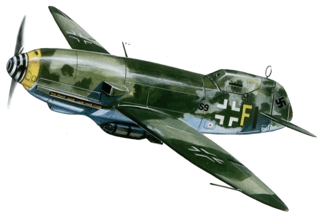
Side profiles by Ed Jackson – www.artbyedo.com


- Cvetković, D. & Cvetković, I. (2016). Borbeni Avioni Prvog Svetskog Rata,, Odbrana Beograd.
- Grosz, P. (1992). Junkers D.I. Berkhamsted, Hertfordshire: Albatros Productions.
- Hofmann, A., Hofmann, T., Mau. & Schmitt, G. (1990). Junkers : Bildatlas aller Flugzeugtypen = Junkers : pictorial record of all aircraft. Berlin: Transpress.
- Gray, P. & Thetford, O. (1962). German aircraft of the First World War. Baltimore, Md: Nautical & Aviation Pub. Co. of America.
- Side view illustrations by Ed Jackson – www.artbyedo.com


.jpg)