World War 2 saw the airplane rise to even greater importance than in the first World War. Air superiority became a crucial component of battlefield operations and air forces were massively expanded during the conflict.The Allied and Axis sides of the war developed enormous war machines, capable of developing and rolling out unprecedented numbers of advanced new military equipment in rapid response to changing conditions on the battlefield, as well keeping up with the technological advances of adversaries.
High altitude bombing raids and night fighting were hallmarks of the War for Europe, whilst aircraft carrier battles pitched the American and Japanese fleets against one another. The technology of the day was pushed to it’s limit with the use of superchargers in aircraft engines, the introduction of radar, and the rapid development of the jet engine by the war’s end.
The period ended as the Nuclear Age and subsequent Cold War were ushered in by the tremendous and tragic blows to Japan’s wearied people.
Empire of Japan (1943) Prototype Fighter Interceptor – 1 Built
The Kawasaki Ki-88 was a fighter interceptor designed in 1942 with the intent of intercepting enemy aircraft heading towards vital military locations. The Ki-88 would never see service, as it was cancelled in 1943 after a mockup and partial prototype were constructed. Although considered by many to be the Japanese copy of the American Bell P-39 Airacobra due to the exterior aesthetic similarities, this is only speculation.
History
The origins of the Kawasaki Ki-88 began in August of 1942 when Tsuchii Takeo, a designer for Kawasaki, responded to a design specification put forward by the Imperial Japanese Army Air Service (IJAAS). The IJAAS determined that they needed an interceptor aircraft that would defend important military assets like airfields, gun emplacements, and others. The specification also stated that the aircraft had to be heavily armed, provide a stable gun platform and be easily flyable by new pilots.
Takeo began work on the Ki-88 and chose to use a 37mm Ho-203 cannon as the plane’s primary armament, with two 20mm Ho-5 cannons to complement the Ho-203. The placement of the guns prompted Takeo to place the engine behind the cockpit. Many sources state that this was done to copy the American Bell P-39 Airacobra, but that claim is debated. The P-39 Airacobra was in service at the time the Ki-88 was developed, but saw limited service with the United States. It did however, see service during the Battle of Guadalcanal. The Japanese were certainly aware of its existence and possibly captured an example of the P-39. If they did indeed capture an example, Takeo could have simply copied the gun and engine placement. It is important to note that such a “rear-engine” fighter configuration was a rarity in plane design at the time. Another common theory is that Takeo came to the same conclusion as H.M Poyer (designer of the P-39) did during the planning phase and designed the plane without copying the P-39. Other than the engine and gun placement, the two planes are quite dissimilar.
Takeo completed the Ki-88’s design in June of 1943. A full scale mockup and prototype were in the works in mid/late 1943, and estimated that the prototype would be completed in October of 1943. However, after the mockup and plans were inspected by representatives of the IJAAS, it was concluded that the Ki-88 had no real improvements over other designs of the time, and the top speed was only slightly better than the Kawasaki Ki-61 after calculations. The IJAAS immediately lost interest and ordered Kawasaki to cease all work on it.
Design
The Ki-88 was a single seater, single engine fighter powered by a Kawasaki Ha-140 engine producing 1,500hp while driving a propeller using an extension shaft. The radiator was placed under the cockpit at the bottom of the fuselage. There was an air intake placed beneath the fuselage on the left to provide cooling for the supercharger in the Ha-140.
The Ki-88 used a conventional landing gear, in which the main wheels could be retracted into the wings while the tail wheel stayed fixed. There was a fuel tank in each of the wings, beside the landing gear wells.
The size of the Ho-203 canon prevented Takeo from placing the engine into the nose which led him to place it behind the pilot’s cockpit, much like the American P-39 Airacobra. Moving the engine to the back of the cockpit was a smart move, as it theoretically would have made the plane a more stable gun platform. Under the Ho 203, on both sides of the nose, there were two 20mm Ho-5 cannons.
Operator(s)
Empire of Japan – The Ki-88 was supposed to have been operated by the Imperial Japanese Army Air Service, but never did so due to the design being deemed as inferior to the Ki-61 and was thus cancelled.
The Beechcraft XA-38 Grizzly was an experimental attack aircraft stemming from a USAAF requirement for a two seated attack bomber. Two prototypes were constructed between 1944 and 1945, and saw extensive testing within the US. The Grizzly showed promising performance, but was ultimately cancelled due to the engines intended for use was given priority to the Boeing B-29 Superfortress and the inevitable victory of the Allies.
History
Bottom view of Beechcraft XA-38 (S/N 43-14407) in flight. (U.S. Air Force photo)
In 1942, the United States Army Air Force (USAAF) issued a requirement for a two seater attack bomber. Beechcraft was quick to respond, and proposed their design to the USAAF. The USAAF was very interested in the design, and ordered two prototypes to be constructed in December of the same year after granting the contract to Beechcraft. In anticipation of the two prototypes, the USAAF assigned serial numbers to them, being “43-14406” and “43-14407”.
Beechcraft specifically designed the Model 28 to be able to destroy gun emplacements, ships, armored vehicles and bunkers while keeping great maneuverability and able to remain airborne after being damaged. All of this would be done by the addition of a powerful 75mm T15E1. The task of developing the Grizzly was given to a team led by Bill Cassidy with Jess Vint and Alex Odevseff in charge of designing the armaments, Bill Irig in charge of the control surfaces, Gus Ericson in charge of the design of wings, Mervin Meyers in charge of hydraulics, Ralph Harmon in charge of the landing gear structure and Noel Naidenoff in charge of the engine compartment. The Grizzly is common thought to be a modified Model 18 design, but this is untrue. The Grizzly did take inspirations from the Model 18, though.
Beechcraft XA-38 during ground vibration tests. Tests were set-up to determine natural frequencies excited during engine operation. (U.S. Air Force photo)
The first Grizzly (43-14406) was delivered to the Army Air Force and flown on May 7th of 1944 by test pilot Vern L. Carstens. The first test flight went relatively well except for an unplanned touch-and-go during landing. This was due to Carsten’s inexperience with landing such a large plane. The first prototype had no armaments installed, but had a wooden mockup of the 75mm T15E1 cannon. In the next few test flights, the Grizzly proved itself to be very aerodynamically stable, and made a good impression with the designers. A memorable flight test includes a performance comparison between the Grizzly and a recently manufactured North American P-51B. The Grizzly and P-51B were put in a mock pursuit, and the P-51B was reported to have been unable to keep up. Afterwards on July 7th of 1945, the first Grizzly was transferred to Wright Field to be used by the USAAF. It then participated in 38 test flights from between October 13 and October 24 of 1944 flown by Captain Jack W. Williams. Williams affectionately noted that the Grizzly was a great aircraft and “very maneuverable” for an aircraft of its size. It is also interesting to note that the turrets on the first Grizzly were dummies.
Front view of Beechcraft XA-38 (S/N 43-14407) in flight. (U.S. Air Force photo)
The second Grizzly (43-14407) had its maiden flight on September 22nd of 1945, once again piloted by Carstens. The second prototype was intended for armament testing, so it had all weapons fitted. The 75mm T15E1 prototype cannon was already successfully tested the year before on July 1st. The second Grizzly flew a total of 38 hours afterwards in tests at Eglin Field in Florida.
As successful as the Grizzly was, it would never reach mass production status because of two reasons. The first reason was that the R-3350 engines were in short supply, as the Boeing B-29 Superfortress had top priority for the engines. Second, the war situation was already in America’s favor, thus cancelling out the need for such an aircraft. As a result, both of the Grizzlies were retired from active service. One was scrapped while the other one was transferred to the Davis-Monthan Airfield in Arizona, meeting an unknown fate.
Design
The XA-38 Grizzly was an all metal, two seat, twin engined semi-monocoque plane with cantilever wings, conventional landing gears, oleo-pneumatic shock absorbers and hydraulic brakes. It was powered by two Wright R-3350-43 Duplex Cyclone engines, the same engine that powered the Boeing B-29 Superfortress. The propellers measured at 4.32m (170in) each in diameter.
The plane used flush riveting and butted skin joints to give the plane its pristine, shiny look. The foil used to construct the wings were derived from the NACA 23000 series which was good for high and low speeds. The engine hub was made from stainless steel and aluminum alloy. The oil coolers were placed in the wings. Four fuel tanks were installed in the wings with a capacity of 2,422 litres (640 US Gallons). Two self-sealing fuel tanks were also placed behind the cockpit which can carry 681 litres (185 US Gallons) if needed to. There were pumps and connectors installed onto the tanks, which would stop fuel flow if the tanks took damage.
Beechcraft XA-38 (S/N 43-14407, the second and last XA-38 built). (U.S. Air Force photo)
As for armaments, the XA-38’s 75mm T15E1 was the defining feature. Could carry 20 rounds fed by a Type T-13 feeding system. There would be a Type N-6 reflector sight to help the pilot aim. The cannon would fire every 1.2 seconds if the pilot pressed the trigger button. Two .50cal (12.7mm) M2 Browning machine guns were installed under the cannon with 500 rounds each. The entire nose section of the XA-38 could be unhinged, where mechanics can easily access the guns for maintenance.
The Grizzly had two turrets, one located on the top of the fuselage and one on the bottom. The turrets were manufactured by General Electric and had two M2 Brownings each with 500 rounds. These two turrets were controlled by a single gunner seated in the rear fuselage. He would aim the guns with a periscope to control the turrets. Interestingly enough, the turrets can also be fixed to fire forward to accompany the T15E1. Ordinance wise, the XA-38 was designed to carry a wide range of things. It could have carried bombs, napalm, torpedoes, fuel tanks, smoke tanks and depth charges.
Operators
United States of America – The USAAF was the sole operator of the XA-38. The USAAF extensively tested the XA-38, and concluded it was a success. However, the XA-38 never reached mass production status.
Beechcraft XA-38 Grizzly
Wingspan
64 ft 4 in / 20.52 m
Length
51 ft 9 in / 15.77 m
Height
15 ft 6 in / 4.72 m
Wing Area
626 ft² / 58.15 m²
Engine
2x Wright R-3350-43 Duplex Cyclone (2,300hp)
Fuel Capacity
640 US Gallons / 2,422 L
Additional Tanks: 185 US Gallons / 681 L
Maximum Takeoff Weight
35,265 lbs / 15,996 kg
Empty Weight
22,480lbs / 10,197 kg
Wing Loading
56.3 lb/ft² / 275.1 kg/m²
Power Loading
7.67 lb/hp / 3.48 kg/hp
Climb Rate
2,600 ft/min / 792 m/min
Maximum Speed
330 mph / 531 km/h at Sea Level
348 mph / 560 km/h – at 5,000 ft / 1,525 m
370 mph / 595 km/h – at 17,000ft / 5,180m
Cruising Speed
(75% Throttle)
289 mph / 465 km/h – at Sea Level
350 mph / 563 km/h – at 16,000 ft / 4,875 m
Range
1,625 mi / 2,615 km – at 225 mph / 362km/h
745 mi / 1,200 km – at 289 mph / 465 km/h
Service Ceiling
29,000 ft / 8,840 m
Crew
1x Pilot
1x Gunner/Observer
Forward Firing Armaments
1x 75mm T15E1 (20 rounds)
2x 12.7mm M2 Browning (500 rpg)
Defensive Armaments
2x 12.7mm M2 Browning (Upper Turret) (500 rpg)
2x 12.7mm M2 Browning (Belly Turret) (500 rpg)
Ordinance
Planned Options:
Bombs
Fuel tanks
Napalm
Torpedoes
Depth Charges
Smoke Tanks
Gallery
Grizzly Prototype 314407 – armed with two 500 lb bombs
The XB-19 was a heavy bomber designed in 1935 to fulfill a request made by the United States Army Air Corps (USAAC) to develop an experimental heavy bomber with extreme range. Although slow in its development and obsolete by the time it was produced, it served as a test vehicle to evaluate plane and engine performances. The sole XB-19 was converted to a cargo transport plane and was eventually scrapped in 1949. The XB-19 was the largest plane operated by the USAAC and USAAF until the Convair B-36 came into service.
History
The roots of the XB-19 can be traced to 1935 on February 5th when the United States Army Air Corps (USAAC) commenced “Project D”. The purpose of Project D was to experiment with the maximum distances achievable with bombers. The USAAC contacted and discussed the project with Douglas Aircraft Company and Sikorsky. Douglas representatives agreed to the terms of the design and plans were made during a conference on June 5th, 1935. The initial plan was to begin the basic design on July 31st of 1935, detailed designs on January 31st of 1936, and have the plane physically produced by March 31st, 1938. The plan however was soon found out to be too ambitious, with the designers underestimating the work required. The designers would be plagued with a lack of proper funding and the sheer enormity of the task. The project would finally be completed in May of 1941, nearly four years after the original deadline.
Douglas XB-19 under construction. (U.S. Air Force photo)
Douglas Aircraft Company received a contract to the project in October of 1935 which required Douglas to create a general and detailed design of the plane, create a mockup of the plane and test the wing centre section, undercarriage, and engine nacelles of the plane. Douglas accepted the contract on October 18th. Later that year, the USAAC would evaluate the mockups provided by Douglas and Sikorsky. Douglas’s design was ultimately chosen, and was given the task of further developing the plane.
The XB-19 under construction at the Douglas Aircraft Factory located in Santa Monica, California. 1940.
The plane would be known as the “XBLR-2” (Experimental Bomber Long Range 2) in its early stages of development. The progress of developing the bomber proved to be tedious and slow. Lack of funding would severely hinder work on the plane. During that time the USAAC made a change to the requirements, the plane was suppose to be powered by four Allison XV-3420-1 engines producing 1,600 horsepower each, but was ordered to be replaced by four Wright R-3350 engines producing 2,000 horsepower each instead. This would also hinder work as the plane had to be slightly redesigned. As time went on, Douglas had to loan a Douglas OA-4A from the USAAC to test an experimental tricycle landing gear configuration intended for the XBLR-2. The tests proved to be a success. Later, the XBLR-2 would be redesignated as “XB-19” (Experimental Bomber 19). Douglas eventually managed to scrape together enough funds to produce a prototype, and the production was authorized on March 8th of 1938.
The XB-19 parked at Mines Airfield. (Colorized by Michael J.)Washing XB-19 at March Field 1941. (Colorized by Michael J.)
During its development, the Douglas company had many problems with the XB-19. They were forced to allocate more funds than initially expected, and needed design staff to work on other aircraft which had a more promising production future. They claimed the XB-19’s design was obsolete due to the production delays it suffered over the past three years and the fact that the plane’s weight was far heavier than expected. The Douglas company officially made a recommendation to cancel the XB-19 project on August 30th, 1938. This recommendation was denied by the USAAC. Interestingly enough, two years later, the USAAC would suggest that the slow development of the XB-19 already rendered the project obsolete when they removed the plane from the top secret classified list. The XB-19 would finally be completed in May of 1941.
The XB-19 parked on the ground next to a P-40 Kittyhawk.
Shortly after completion, the XB-19 was used in taxiing tests on May 6th, 1941. The flight test was scheduled to be on May 17th, but was postponed three times due to critical mechanical errors. The landing gear brakes were found to have defects, its engines had backfiring issues, and the propeller pitch control system had to be worked on. On June 27th however, the XB-19 would finally have its maiden flight. In the maiden flight, seven crewmembers were on board with Major Stanley M. Umstead in charge. The flight lasted 55 minutes from Clover Field in Santa Monica to March Field. The flight went by smoothly without any problems and was successful. Shortly afterwards, Donald Douglas would receive a congratulatory telegram from President Roosevelt. The USAAC unofficially accepted the XB-19 in October of 1941.
Eager observers watch the XB-19 preparing for its maiden flight. Clover Field, 1941.
After the Japanese attack on Pearl Harbour on December 7th of 1941, the United States was on high alert. The XB-19’s turrets were armed and a new layer of olive camouflage paint was applied, replacing its bare metal USAAC livery. It would make 4 more tests flights in California before being transferred to Wright Field on January 23rd, 1942 as another safety measure. By then, the XB-19 had over 70 hours of flight time.
The XB-19 was finally accepted officially by the USAAF in June of 1942 after minor modifications were made to the plane’s brake system. The contract cost to the United States government was $1,400,064. The Douglas Aircraft Company also spent $4,000,000 in personal company funds. The XB-19 was extensively tested by the USAAF for eighteen months to see the engine performances and different altitudes and the maneuverability of the aircraft. The results of these tests would later go on to influence the design of the Boeing B-29 Superfortress and the Convair B-36. The XB-19 performed well in all aspects and was generally free of problems. The only problem noted however was the inefficient engine cooling process. Due to this, the cooling gills on the plane had to be open the whole time in longer flights, thus reducing the effective speed of the XB-19.
The XB-19 in flight over Santa Monica with an AT-6 following it.
After the XB-19 was thoroughly tested and experimented with, the USAAF no longer had a need for it. It was brought to the Wright Field and modified to be a cargo transport aircraft. It was refitted with Allison V-3420-11 engines and had its armaments removed. The new aircraft would be designated “XB-19A”. For the next two and a half years, the XB-19A would fly to numerous airfields within Ohio. It was documented to have been stationed at Wright Field, Patterson Field, Lockbourne Air Base, and Clinton Country Air Base. The XB-19A would make its last flight on August 17th, 1946, where it flew to the Davis-Monthan airfield in Arizona from Wright Field to be stored. It stayed in storage for three years before finally being scrapped in 1949, thus ending the legacy of the XB-19.
The XB-19 in flight some time in 1942. (Colorized by Michael J.)
To this day, only two wheels of the XB-19’s landing gear survives. One can be seen in the Hill Aerospace Museum in Oregon, and the other can be seen in the National Museum of the United States Air Force in Ohio.
The wheel of the XB-19 with a car and person for comparison.
Design
The XB-19 is described as a colossal, all metal low wing monoplane installed with a conventional tricycle landing gear. The two main wheels of the landing gears measured at 2.44 m (8 ft) in diameter, which was impressive for the time. The original design specifications ordered wanted the engines to be four Allison XV-3420-1, but was swapped for four Wright R-3350-5 engines instead with a three blade metal propeller with a 5.18 m (17 ft) diameter. The engines would be switched once again to Allison V-3420-11 after the plane was repurposed as a cargo transport aircraft. The plane could carry an impressive amount of fuel, at 38,178 L (10,350 US Gallons) in its auxiliary fuel tanks, with an optional 3,210 L (824 US Gallons) that could be stored in the bomb bay.
A shot of the underside of the XB-19 with the gear down.
The XB-19 carried 8,480 kg (18,700 lbs) of ordinance usually, but could be overloaded to 16,828 kg (37,100 lbs) if fuel was reduced significantly. As for armaments, the initial prototype was unarmed. Later though, two 37mm Oldsmobile T9 autocannons, five 12.7mm M2 Brownings and six M1919 Brownings were fitted to the plane. One T9 was fitted to the nose while the other was fitted to the upper front turret, each accompanied by a single M1919 machine gun. There would be one M1919 on each side of the bombardier’s position, and a M1919 on each side of the stabilizer. A single M2 Browning was fitted in the tail of the XB-19, two M2 Brownings on each side of the galley compartment, one in the bottom turret, and one in the upper powered turret.
In the crew compartment, there was eight seats and six bunks. The compartment could accommodate two flight engineers, and six relief crew members. The normal combat crew consisted of sixteen people. (Refer to Specifications Table).
The cockpit of the XB-19.
Variants
XB-19 – The original model and design. Initially developed as a long range heavy bomber for the USAAC, but was outdated by the time it entered service. It served as a “flying laboratory”, testing engine performances and plane handling. It was converted to the XB-19A after the USAAF no longer had use for it.
XB-19A – The XB-19A was a converted XB-19 using improved Allison V-3420-11 engines. It was used as a cargo transport aircraft after the air force was done experimenting with it. All armaments were removed. It was scrapped in 1949.
Operators
United States of America – The XB-19 and XB-19A was operated by the USAAC and USAAF throughout its service life.
Douglas XB-19
Wingspan
212 ft / 64.62 m
Length
132 ft & 4 in / 40.34 m
Height
42 ft / 12.8 m
Wing Area
4,285 ft² / 398.091m²
Wing Loading
32.6 lb/sq ft / 159.5 kg/sq m
Power Loading
17.5 lb/hp / 7.9 kg/hp
Engine
4x Wright R-3350-5 Duplex Cyclone (2,000 hp)
Fuel Capacity
10,350 US Gallons / 38,178 L – in auxiliary fuel tanks + 824 US Gallons / 3,120 L – in bombay (Optional)
Maximum Weight
140,000 lbs / 63,503 kg
Empty Weight
86,000 lbs / 39,009 kg
Climb Rate
650 ft/min / 198 m/min
Speeds
Cruising: 135 mph / 217 km/h – Sea Level
Operational: 186 mph / 299 km/h – @ 15,700 ft / 4,785 m
Maximum Speed: 224 mph / 360 km/h – @ 15,700 ft / 4,785 m
A spectacular shot of the XB-19 flying low. 1942.XB-19A on the ground with Allison V-3420-11 engines.Crewmen washing the XB-19 at March Field, some time in 1941.The crew of the XB-19 operating in the cockpit.XB-19A on the ground with Allison V-3420-11 engines.A photo of the XB-19 post-war before it was scrapped.
Empire of Japan (1945) Prototype Special Attack Aircraft – 3 Built
The Ta-Gō was an attempt at creating an easily made and cheap kamikaze aircraft in anticipation of Operation Downfall and Operation Olympic. The plane would have been used by special “shinpū” (kamikaze) units to ram advancing Allied tanks, infantry and boats. Fortunately for the Allies, the Ta-Gō project was cancelled once the Empire of Japan capitulated.
History
The concept of the Ta-Gō came in late 1944, when Japan was on its heels after losing the majority of its territories to the Allies. With the recent loss of Guam, Okinawa, Iwo Jima, and other islands, Japan was convinced that the American invasion of the Japanese mainland was inevitable. By 1945, Japanese factories and industries suffered from constant bombings by the USAAF. This led to the deprivation of much needed materials to produce planes and tanks. Because of this, much of the already existing aircrafts were designed to be built with wood. (Example: Ki-106 from Ki-84, D3Y from D3A). Even then, Japan’s industry could barely produce such planes due to the situation of the war.
Watching his country’s resources slowly depleting and the rapid advance of the Allies, IJA Captain Yoshiyuka Mizuyama wanted to make a difference. He wanted to design a simple, cheap and easily producible plane requiring minimum materials for designated kamikaze units. If the Ta-Gō was mass produced, it could easily fill already depleted kamikaze units, and would make kamikaze attacks more popular. Once Mizuyama finished designing the plane, he went to Tachikawa Hikōki Kabushiki Kaisha (Tachikawa Aircraft Company) and submitted his design. His design was however rejected because Tachikawa Hikōki simply could not afford to allocate resources for the Ta-Gō. It was also rejected due to the fact that Mizuyama’s design was not officially approved by the state.
Determined to initiate his project, Mizuyama looked around the city of Tachikawa until he discovered a small woodwork shop. He rented the shop and began constructing his first prototype with the help of his men. Around February of 1945, Tachikawa was firebombed by the USAAF. The workshop was completely destroyed along with the sole prototype. Still determined to initiate the project despite the major setback, Mizuyama approached Nippon Kokusai Kogyo K.K (Japanese International Aviation Industries Ltd) to continue his project. Luckily for him, Kokusai accepted his project. Since Kokousai accepted the project, they asked that Mizuyama redesign certain parts of the plane to so that it would require even less materials and manpower. The Kokusai design’s dimensions was significantly scaled down compared to Mizuyama’s original design and was simpler altogether.
Now satisfied that his work was accepted, he began building the new model of the Ta-Gō with help from Kokusai. The prototype was completed around the middle of June, and was test flown for the first time on June 25th, 1945 with an experienced pilot from Kokusai in the cockpit. The test pilot expressed obvious handling concerns and gave helpful tips to the designers. As a result, the Ta-Gō participated in more test flights and was modified on the drawing board. In the end, the blueprints for the production variant were finalized. Unfortunately for Mizuyama and Kokusai, the Empire of Japan surrendered to the Allies in August of 1945, and the Ta-Gō never entered production. Interestingly enough, the Allies discovered two variants for the Ta-Gō named “Gi-Gō” and “Tsu-Gō” after Kokusai surrendered all their documents. However, there is no known information on them today.
Tachikawa, funnily enough, took on the project too after the Kokusai prototype was completed and authorized by the Gunjushō (Ministry of Munitions) despite them rejecting the project earlier. Once the American Occupation forces arrived in Japan, they found the Tachikawa Ta-Gō incomplete. Once the Ta-Gō was accepted, it was given the designation Ki-128. It is not confirmed whether the designation was for the Kokusai or Tachikawa variant or both.
Design
The Ta-Gō was a single seated kamikaze plane made mostly out of plywood, fabric, and wood lathes. The original Ta-Gō design used wood lathes for the fuselage and structure, and used plywood and fabric for the outer skin and control surfaces. The pilot’s compartment featured a simple acrylic glass. The landing gear was fixed, meaning they couldn’t be retracted. It featured a Hitachi Ha-13 Ko 9-cylinder radial engine that produced 450hp, with thin steel sheets as the engine cowling. The only armament it could carry was a 500kg bomb, which cannot be released. Other than these details, little is known about the original Ta-Gō as hardly any evidence exists.
The refined design for Kokusai made the Ta-Gō much smaller than its original size. Due to this, the plane could no longer house the Hitachi Ha-13 Ko, and was replaced by the Hitachi Ha-47 11 producing 110hp instead. Because of the severe engine power decrease, the 500kg bomb load had to be changed to 100kg. Another change from the original design was the cockpit was open topped. The only thing that covers the pilot is a simple acrylic glass pane that shields from the wind. As for the engine, it was protected by an angular wooden cowling. The engine was paired with a two-blade fixed pitch wooden propeller. The engine mount was made of metal, with the fuel tank placed on top of the engine, thus using a gravity feed system. In between the acrylic glass pane and the fuel tank, there was an oil cooler. As for cockpit instruments, only the very basic and important ones were kept. Such instruments used were a compass, speedometer, altimeter, and engine-related gauges such as fuel and oil. The fuselage was also boxier than the original design. This design feature was extremely simple to manufacture, but was very un-aerodynamic.
The fuselage and structure was made with wooden spars and plywood, much like the original Ta-Gō. The wings were rectangular shaped, and were hinged near the landing gear, which allowed the the wings to fold upwards. The reason why the wings could be folded was because the Ta-Gō was suppose to be hidden in caves and take up less space in the factory line. The rudder and elevator of the Ta-Gō were both rectangular shaped. As for the landing gear, it was made out of steel tubing and paired with rubber wheels. Each landing gear was supported by a metal strut.
Variants
Original Ta-Gō: The original Ta-Gō was powered by a Hitachi Ha-13 Ko (450hp) and could carry a 500kg bomb. It was almost completed before being destroyed in a bombing raid. Only one photo of the original prototype is known to have existed.
Revised Ta-Gō:The revised Ta-Gō design featured a smaller airframe to save the factories effort and materials. As a result of this modification, the engine had to be changed to a Hitachi Ha-47 11 (110hp) and the bomb load was reduced to 100kg. Two of these were made. One was completed by Kokusai, test flown and evaluated while the other one by Tachikawa was incomplete.
Gi-Gō: The Gi-Gō was a late war development of the Ta-Gō. There is no information known about it to this date. The project was commenced by Kokusai.
Tsu-Gō: Like the Gi-Gō, the Tsu-Gō was developed very late in the war. No information about it has been discovered to this date. The project was commenced by Kokusai.
Operators
Empire of Japan – The Ta-Gō would have been used by special kamikaze units in both the army and navy.
Ta-Gō (Revised Version)
Wingspan
8.90m | 29.2ft
Length
7.40m | 24.3ft
Height
3.87m | 12.7ft
Wing Area
5.10m² | 54.9ft²
Engine
Hitachi Ha-47 11 (110hp)
Take-Off Weight
565.5kg | 1,290lbs
Empty Weight
345.5kg | 761lbs
Maximum Speed
195km/h | 121mph
Cruising Speed
179km/h | 111mph
Range
150km | 93 miles
Maximum Service Ceiling
4,600m | 15,091ft
Crew
1 (pilot)
Armament
1x 100kg bomb
Gallery
The never completed first Tachikawa prototypeArtist Interpretation of a completed first Tachikawa prototype
Nazi Germany (1942)
Light Transport and Trainer – 1,216 Built
The Siebel Si 204 was a twin engined light transport and trainer aircraft built by Siebel for the Luftwaffe in World War II.
History
Si204s under construction
The story of the “Siebel” factory starts in the 1934, with the founding of “Hans Klemm – Flugzeugwerke Halle“ that was a branch of “Leichtflugzeugbau Klemmin Böblingen”. In December 1937 the name changed to “Siebel Flugzeugwerke“ when it was taken over by Friedrich Siebel.
Initially Siebel had a license to produce the Focke-Wulf Fw 44 “Stieglitz” and later during the war Heinkel He 46, Dornier Do 17 and the Junkers Ju-88. In addition to the production of licensed aircraft, in 1937, “Siebel” produced its own aircraft under the name Fh 104. It had its first test flight that same year, and some 46 planes where build during the period of 1938-42. The Fh 104 made a number of notewortly flights:
In March of 1939 flying a 39975 km tour of Africa,
Winning the “Littorio rally in Italy”,
And flying a 6200 km across 12 countries in 1938 (Europa Rundflug).
Color photo of Luftwaffe Si204
By the end of 1930, “Siebel” company was commissioned by the Luftwaffe to design a new type of all-metal twin-light light transport aircraft with a capacity of eight persons with two crew members. In 1940 the first prototype of the twin engine and larger and also heavier Si 204 appeared with originally a conventional stepped cockpit and a powerplant of two 360 hp (268 kW) Argus As 410 engines . The prototype made its first flight during the period of May to September 1940. Second prototype made it first test flight in early 1941. The third prototype was re-designed as a trainer aircraft for blind flying. Because of this, its first test flight was only possible at the end of 1941 or the beginning of 1942. The other 12 planes produced by “Siebel” were used for general flight evaluation. After this small production run Siebel stopped building this aircraft, and future planes would be built in France and Czechoslovakia.
Model A was build in relatively small number by the French “SNCAC” (Société Nationale de Constructions Aéronautiques du Nord) factory. It was designed as a transport and communication aircraft.
Si204A
The next model D appeared in 1942, with a new glazed nose and cockpit with no separate flat windscreen for the pilot. Almost all German bomber aircraft during the war shared this design. The D model also had more powerful 600 hp As 411 engines. The D model was used for radio navigation and for training. This model was mostly used during the war.
The production of the D-3 version start in October 1944 by the “Aero” company. The D-3 had wooden wings and a tail-plane made of wood because due to material shortages. In France, production of this aircraft was stopped in August 1944 as a result of the Liberation.
“BMM” produced the aircraft until October 1944 and then changed to producing spare parts for the Si 204. The “Aero” was scheduled to cease production of the D-1 in March 1945 after building 486 aircraft and then switch to D-3 only. The E version was built in limited numbers and can be considered as an experimental series.
After the war, production of Si 204 continued in Czechoslovakia and France. Czechoslovakia produced some 179 Si 204D, developed into military trainer variants Aero C-3A, passenger variant C-103 and military transport variant D-44. France produced 240 transport NC.701 Martinets and a number of passenger NC.702 Martinets.
Si204 in French Service
Operational history
Si204D Armed Version
During the war the Luftwaffe put the plane to use for transport, communication while also seeing use as an advanced trainer and blind flying trainer.
It was generally regarded as a good plane, but with some drawbacks like the lack of any armament, which prevented many exercises for the combat training program and possible use as a combat aircraft, although for this role it is not designed.
Designers in Halle had developed few different military projects, like installing bomb racks, machine gun turrets and other necessary equipment, but none of these plans were ever realized. This problem was attempted to be solved with some modified Si 204D airplanes with three 13mm MG 131 machine guns, intended to be used as a night combat aircraft but this model was not used in combat and was built in limited numbers.
Despite these unsuccessful attempts, Germans tried to make a new bomber variant, in order to be used in anti guerrilla fighting with a built to this specification. Three Si-204E were sent to the military tests in Belarus. They were treated as special anti-guerrilla aircraft. The scope of the actions of the Belarusian partisans forced the Germans to throw against them not only regular troops, but armored vehicles and aircraft. The extent to which they were used in this role remains unknown.
Si 204 is reported to has the “honor”, of being the last German aircraft shot down on the Western Front. On May 8, 1945 an Si 204 was shot down by an American P-38 Lightning, three miles southeast of Rodach, Bavaria.
Production variants
Closeup of Si204 Engine Nacelle
Because Siebel produced the Junkers Ju-88 under licence and the need for as many military aircraft as possible, Germans decided to increase the volume of production for this aircraft. This was done by moving the production to French “SNCAC” and Czechoslovakian “Aero”, and “ČKD-BMM” factories. The “SNCAC” produced some 168 aircraft and the “Aero” and “ČKD-BMM” produced 1033 aircraft, Siebel produced only the first 15 prototype Aircraft, before the production was stop in favor of Ju-88. In total some 1,216 aircraft of this type where build, during the war.
During WW2
Si 204 – Prototype version with 15 plane build by Siebel (Number V1 to V15),
Si 204A – Model A was a transport and a communication aircraft, with crew of two and eight passengers.
A-0 – Passenger plane version,
A-1 – French built version.
Si 204B and C – Were paper projects
Si 204D – Model with a new glazed nose and cockpit and with two 600 hp As 411 engines. Model D was used for radio navigation and for flying training.
D-0 – Blind flying trainer,
D-1 – Czechoslovakian production version,
D-3 – This model had wooden wings and tailplanes, in order to save on metal.
204E – Experimental night fighter plane. This model had on its nose two 13mm MG 131 machine guns plus one more machine gun (same caliber) in a glazed cupola on the upper hull of the plane. This model was not used in combat and was build in limited number using rebuild Si 204D planes.
E-3 – Proposed version to be armed with bombs, and to be used in anty guerrilla fighting, possibly only few were build.
Flying carrier – Paper project that was originally intended to carry one DM-1 (Doctor Alexander Lippisch plane) on the back of a Siebel Si 204. Little is known about this project
Postwar
Czechoslovakia Version:
Aero C-3 – Used for flying and crew training,
Aero C-103 – Used for Civilian transport,
Aero D-44 – Military transport version.
France versions:
SNCAC NC.701 Martinet – Military transport version with SNECMA 12S-00 air-cooled V-12 engines,
SNCAC NC.702 Martinet – Improved Passenger transport version.
Operators
Germany – Most produced planes where used by the Luftwaffe as advanced schools training, transport, blind flying trainer (usage in this role was at best was sporadic) and communication. There were plans for arming this plane for night fighter and anti-partisan operatons, but it all left on paper only with few model build and not a single one was used in combat.
Czechoslovakia – Used German build planes and the new Aero C-3 version after the war.
France – Used some captured German planes and also the NC. 701 version which was build by France after the war.
Hungary – Operated some C-3 Aero version after the war.
Poland – Used six NC.701 version.
Soviet Union –They were captured in some numbers at the end of the war. At first, the captured Si-204 was mostly used by the military. The headquarters of many regiments and divisions stationed in Germany used the Siebel for official flights, but only for short period.
Sweden – Operated five NC.701 (1962-1970) for mapping photography.
Switzerland – Operated some Si.204 D planes.
Specifications (Si 204D)
Wingspan
70 ft / 21.33 m
Length
39 ft 3 in / 12 m
Height
14 ft / 4.25 m
Wing Area
495 ft² / 46 m²
Engine
2x Two Argus As 411 12 cylinder inverted piston engines (447kW/600 hp)
The Saab B 17 is the product of Sweden’s need to procure assets to defend its sovereignty and neutrality in the light of a gradually complicated international and regional context, to the point that it was prioritized over the equally capable and versatile Saab B 18. This aircraft was a milestone for the main company in the Swedish aerospace industry, as it was the very first airplane produced and delivered by this company following its acquisition and merge with ASJA, the aircraft branch of the Swedish Railroad Workshops company. It was also the application of the lessons and experience provided by the licensed-manufacturing of the Northrop 8-A1 bomber by AJSA/Saab. AJSA was already commissioned by the Defence Material Administration to develop and build a single-engine and light fighter-bomber, so Saab took over the design and development process in 1939 after both companies merged, evolving into the final light bomber, dive bomber and reconnaissance aircraft. Designated as the L 10 by ASJA, the design became the Saab 17, incorporating a good number of innovations and becoming a very versatile and adaptable airframe. Yet its time of service with the Flygvapnet was rather brief, as it was de-commissioned by the late 40’s. This was due to new and more powerful powerplant technologies such as jet propulsion. Instead, it served for a long period of time in Ethiopia until 1968.
The Saab B 17 is a light bomber/dive bomber and reconnaissance plane with two seats, a single engine and a single tail, whose design bears a close resemblance with the Mitsubishi Ki-30 “Ann”, the Mitsubishi Ki-15, the Vought OS2U, and the Curtiss SB2C Helldiver, especially with the elongated shape of the main airframe and equally elongated windscreen of the cabin (as well as the same cockpit), which occupies most of the superior area of the airframe and it is fully incorporated in the fuselage. The wing is a mid-wing (cantilever) of trapezoid shape with a remarkable characteristic: where the retractable landing gear, which was covered with streamlined fairings, was placed, the rear part of the wing was divided. From the fuselage to the place of the landing gears, it was straight; from the landing gears area to the wingtip, it was angled. The forward area of the wing was straight, and the wingtips were rounded. The wing, from a frontal perspective, was slightly angled upwards from the landing gear area to the wingtip. It was also a reinforced wing to allow it to deal with the high stress by dive bombing missions.
The Saab B 17 was powered by different powerplants during its career, as many versions had their own powerplants. The two prototypes (L 10) were powered by a licensed-built Bristol Mercury XII of 880hp by NOHAB (Nydqvist & Holm AB) and by a Pratt & Whitney R-1830 Twin Wasp of 1065hp each. The first production version (B 17A) was powered by the same Pratt & Whitney R-1830 (S1G3C) of 1050hp, while the B 17B (and also the B 17BL and B 17BS) was powered by a licensed-built Bristol Mercury XXIV of 980hp, with the B 17C powered by a Piaggio P.XIbis R.C.40D of 1040hp. Consequently, speed tended to vary from version to version as well. For instance, the B 17A could reach speeds of up to 435 Km/h (270 mph); the B 17B could reach speeds of up to 395 Km/h (245 mph), the B 17BL and B 17BS could reach speed of up to 330 Km/h (205 mph); and the B 17C could reach speed of up to 435 Km/h (270 mph). The landing gear was also varied from version to version, as it could have the classic set of two wheels at the wings and a small tailwheel, skies as replacement for the wheels, and even special twin floats permanently attached. This gave the B 17 considerable versatility, as it could take off and land in normal runways to snow-covered terrain, and also in water surfaces.
The armament had no modifications, comprising of two 8mm Ksp m/22F machineguns placed at the forward section of the wings and after the landing gear area, a single and moveable 8 mm Ksp m/22R machine gun firing backwards for the observer/navigator/radio operator, and a payload of up to a 500-kg (1,102 lb) bomb or 700-kg (1,500 lb) bomb. Interestingly, the dive bomber version had an under-fuselage trapeze to accommodate a 500 Kg bomb, along the wing weapons stations. And it had state-of the art avionics for bombers by the time, like the bomb-sight BT2 (also known as m/42) that increased precision, mostly the late versions. In addition, it had two radios, an FR-2 and FRP-2. The reconnaissance version had a camera placed at the bottom of the fuselage.
The initial roles of the airplane were reconnaissance and artillery spotting, roles that were, however, already filled by other air assets such as the Fieseler Storch and the Hawker Hart. As a result, the new airplane was required to be a light dive-bomber as well. Nevertheless, the final model retained all of the two missions through its variants, as well as receiving a level light-bomber and dive-bomber role. It would also be used for target towing later in its career. The Saab B 17, like the B 18, had an American ‘soul’ as well, thanks to the 40-50 American engineers that were part of ASJA and contributed with the design and construction of the airplane, hence the abovementioned similarity with the American airplanes. And it needed to receive some structural modifications, especially for the dive-bombing missions, such as the reinforcing of the wings and the landing gear folding system. This could be retracted backwards and used as an airbrake, taking advantage of the fairing.
Development of the B 17 began in 1937 when ASJA began works on its L 10; as Saab merged with ASJA that same year, it continued with the development of the given aircraft, which would be an all metal airframe – something that was a novelty as airplanes back then used to have wood and other materials part of the fuselage. Two prototypes were built, each one having a different powerplant and flying for the first time in May 1940. The test pilot, Claes Smith, assessed the design as a good one, despite the fact the cockpit wheel came loose and fell prior landing. During development, it was realized that some modifications were needed, like changing the carburetor air intake from the top of the engine cowling to the starboard side of the cowling. This was done to prevent the engine from stopping. A spin fin was also added. By the end of 1940, the first 8 B 17s were produced, entering in service with the Flygvapnet in 1942. Some issues delayed the production programme, however. Nonetheless, 324 airframes were produced between 1942 and 1944, with three main versions: the B 17A light bomber and later target towing aircraft, the B 18B – and its sub-variants B 17B I, B 17B II, B 17BL and B 17BS – light bomber and reconnaissance versions (this version was the one that received most of structural the modifications), and the B 17C bomber version.
The B 17 had one of the shortest service period with the Flygvapnet, as it was retired 7 years after it was introduced; yet it remained in service in Austria, Finland, and Ethiopia until 1968. In Sweden, they remained in service with civilian operators and in very small numbers until 1959, where they received new avionics.
5 airframes remain, one of them airworthy and still operating today in airshows. Two are museum pieces in Linköping and one in Helsingør, Denmark. Two airframes are reportedly located in Lithuania.
Design
The design of the B 17 is similar to other aircraft used in WWII by other countries, meaning it has the typical ‘WWII style’. But instead of being the average WWII design, the B 17 has some remarkable and particular characteristics. The airplane is an all-metal airframe, with the bow having a cylinder shape thanks to the radial engine and the stern is topped off with the tail, and the overall airframe being elongated with a sort of conical shape. The airplane is also a semi-straight leading-edge wing airplane, but the wings also have a particular characteristic. In fact, the wings have a ‘divided’ shape, with the area of the landing gear being the dividing point. First, from the fuselage to the landing gear, the leading-edge is straight while the rear-edge is also straight, having two ‘dog-teeth’ that mark where the rear area of the fairings are located. Second, from the landing gears to the tip of the wings, the leading-edge of the wings are straight as well, but the rear-edges are angled, making this area of trapezoid shape. The tips are rounded. The wings also have a divided shape from a frontal perspective, with the landing gear being also the dividing area. From the fuselage to the landing gear area, the wing is straight. However, from the landing gear to the tip of the wings, it is angled upwards, similar to the Ju-87 Stuka or the Douglas SBD ‘Dauntless’, only that the angle is not as wide. The wing, furthermore, is installed in the middle of the fuselage (cantilever), also being reinforced. Such reinforcement can be seen through its thickness. The horizontal stabilizers are also of trapezoid shape, with the control surfaces per se having an inwards angle at the tip of the surface. The tail has a similar shape with the rudder occupying most of the surface and having also an inwards angle near the tip. Both horizontal and vertical stabilizers have an equally rounded shape.
The canopy is another remarkable characteristic of the B 17, as it is very elongated, occupying almost 40% of the superior area of the fuselage and making an impression that the B 17 has a crew of three, rather than the actual crew of 2: the pilot and the radio operator/navigator/observer. As a result, the cockpit had a lot of space, which allowed the second crewman to slide the seat back and forwards between the two different workstations. Beneath the forward area of the cockpit was where the bombs bay was located. A long antenna was placed above the canopy, right after the pilot’s seat, with a long cable connecting it with the tail. The landing gear was of classic configuration, with two (extended) wheels placed beneath the wings and a third wheel placed beneath the tail. The two forward wheels have a particular trait that gave the B 17 another distinctive characteristic either in land or when in flight: the forward landing gears were covered with an aerodynamic fairing as it folded backwards, into the wing. The purpose was to use such fairing as an airbrake, yet it was not entirely functional as the hydraulic system wasn’t powerful. The fairings were met by a ‘hood’ of sorts at the wing; when the landing gear folded, it gave the landing gears cover a cylinder shape, making the B 17 to have two cylindrical structures at the wings while in flight, making easy its recognition while in flight. The B 17 went through a series of modifications, especially the reconnaissance versions, as they received floats – with the purpose of operating from water – along with small endplates (placed right before the wing tips) and aerodynamic struts. The landing gear, in turn, could be replaced with skis instead of wheels, an ideal device for winter or Arctic operations.
The B 17 received three different type of powerplants. The first two prototypes were powered by a NOHAB-built Bristol Mercury XII and a Swedish-made Pratt & Whitney R-1830 Twin Wasp engines. The production versions had the following powerplants: a Swedish-made Pratt & Whitney R-1830 Twin Wasp (B 17A); a Swedish-made (by SFA) Bristol Mercury XXIV (B 17B and the different sub-variants); and the Piaggio P.XIbis R.C.40D (B 17C). All the engines were radial and air-cooled, with 9 or 14 cylinders. The propeller was a three-bladed Piaggio P.1001 variable pitch propeller. The engines yielded different speeds. The B 17A could reach speeds of up to 435 Km/h (270 mph), the B 17B could reach speed of up to 395 Km/h (205 mph), and the B 17C could reach also speeds of up to 435 Km/h (270 mph).
The B 17 had a standard armament with no variation from model to model, except for those with reconnaissance tasks. It consisted of two 8mm Ksp m/22F mounted at the wings and firing forwards, and one 8mm Ksp m/22R mounted at the stern of the cockpit, which was moveable and could fire backwards. A 500 Kg (1,102 lb) (B 17A) or a 700 kg (1,500 lb) (B 17B andC) could also be carried. Some units of the B 17A were modified to carry air-to-ground rockets. The reconnaissance versions were fitted with a camera type N2. An advanced bomb sight named the ‘m/42’ was introduced to enhance bombing efficiency, especially at dive-bombing, reducing the angle of bombing.
The B 17 was the very first plane produced by Saab, and incorporated many of the lessons and experiences acquired with the licensed-manufacturing of the Northrop 8-A1 bomber by ASJA and then Saab itself, being also the first then modern all-metal light bomber produced by Sweden during WWII. As the m/42 bomb-sight was developed and introduced for this aircraft, it was reportedly exported to the US.
An ‘all-terrain’ airplane
If there is something that makes the B 17 a remarkable design, it is the fact that modifications to its landing gear allows the plane to operate from any type of terrain… literally. The main landing gear configuration is that with wheels for normal operations in normal airstrips. But when winter comes, the wheels could be replaced with skis, allowing the airplane to operate even in harsh cold weather conditions with snow-covered airstrips. This might indicate that Sweden needed an all-time available air asset to defend its sovereignty and neutrality, or maybe that it absorbed the operational lessons the Swedish Volunteer squadron that took part during the Winter War, or the lessons provided by that same conflict. But the B 17 received another modification that allowed it to operate from the surface of any water body, as it could be fitted with two floats replacing the wheeled-landing gears, becoming the B 17BS. This variant was mainly used for water-borne aerial reconnaissance.
Close to War and the architect of an air force
Despite being a rather obscured airplane in history, the B 17 would have been one of the few neutral airplanes to take actual part in a conflict, besides those belonging to the Flygvapnet that took part during the Winter War. For instance, the Danish Brigade, a unit comprised of refugee Danish airmen supported and equipped by Sweden, would have been close to assist in the liberation of their country, if it weren’t for the fact that the Swedish government did not allow it to take off with the supplied B 17 units to Denmark. The B 17s were then offered to the Danish Air Force, but were rejected as the German surrender took place some days before the offering was made, being returned to the Flygvapnet.
But the adventures of the B 17 would not finish there, Ethiopian country was looking for assistance in building a more advanced air force of its own after WWII. Sweden became the main supporter of this small air force, supplying Saab Safir trainers and B 17 light bombers, as they later were being phased out in 1947. It also employed some former Flygvapnet personnel and under orders of Carl Gustav von Rosen, who also became the chief instructor of the rebuilt Imperial Ethiopian Air Force. It remained in service there until 1968.
Variants
L-10 – The prototype version of the B 17 under the denomination it had when ASJA was tasked with the design and development process. One unit was powered by a NOHAB-made Bristol Mercury XII 880hp engine and another was powered by a Pratt & Whitney R-1830 Twin Wasp engine.
B 17A – Bomber version powered by a Pratt & Whitney R-1830-S1C3G Twin Wasp engine of 1050 to 1200 hp. Some units were modified to carry air-to-ground rockets. The armament of this version became standard for the bombers and its other variants: 2x8mm machine guns placed on the wings and firing forwards, and an 8mm rear machine gun placed at the second crewman’s post, along a 500 kg (1,102 lb) bomb. 132 units delivered.
B 17B – Bomber version powered with a Swedish-built Bristol Mercury XXIV (Svenska Flygmotor Aktiebolaget SFA) engine, with the same armament configuration except for a 700 kg (1,500 lb) bomb. 55 units delivered.
B 17B I – Dive-bomber version fitted with a trapeze under the fuselage, carrying a 500 Kg (1,500 lb) bomb, and underwing hardpoints for bombs. It was equipped with the m/42 bombsight.
B 17B II – A light level bombing version fitted with an internal bomb bay and underwing hardpoints.
B 17BL – Reconnaissance version fitted with a wheeled landing gear and a camera in the fuselage, replacing the HE 5 Hansa and the Fokker C.VD/C.VE. 21 units delivered.
B 17BS – Reconnaissance floatplane version fitted with twin floats, aerodynamic struts, and endplates on the horizontal stabilizers. 38 units delivered.
B 17C – Another bomber version fitted with the Piaggio P.XIbis R.C.40D 1040hp engine, and carrying a 700 kg (1,500 lb) bomb. 77 units produced.
Operators
Sweden The Flygvapnet was the main operator of the B 17, with 132 units of the B 17A model, 55 units of the B 17B and its modified sub-variants, and 77 of the B 17C variant. The first model was fitted with an inner bomb bay with some airframes modified to carry air-to-ground rockets. The following version was used as bomber – equipped with the advanced m/42 bombsight and some with the trapeze and underwing hardpoints – up until 1945. Some airframes were modified for reconnaissance duties and subsequently equipped with cameras. These modified aricraft served until 1949. Some airframes received further modifications such as the twin floats and other structural modifications. The B 17C was used for bombing missions, having an internal bomb bay and hardpoints until 1948, when they were withdrawn due to problems with the engines. The B 17 operated in six squadrons from 1942 to 1949 as it follows: the B 17 bomber and dive-bomber versions operated in F4 Frösön, F6 Karlsborg, F7 Stenäs, and F12 Kalmar. The B 17BS sea-based planes operated with F2 Hägernäs, and the land-based reconnaissance planes operated in the F3 Malmslätt.Following the B 17 withdrawal from service with the Flygvapnet, the airplane was operated by civilian companies for various purposes, target towing included. Two B 17BS were purchased by the Osterman Aero and used to carry fish and shellfish from Bergen (Norway) to the Swedish capital. In addition, 19 B 17A were loaned to AVIA and Svensk Flygtjänsk AB and modified for target towing; 5 of them received ECM equipment in 1959. One B 17A remains airworthy in airshows, with 2 additional airframes used as museum displays.
Finland The Ilmavoimat (Finnish Air Force) received two B 17A for target towing tasks, which were lost in accidents.
Austria The Österreischische Luftstreitkräfte (Austrian Air Force) received a B 17A via Svensk Flygtjänsk AB in 1957. This was done to facilitate the deal as it was a privately-owned airplane, considering the restrictions the Swedish government sets on sales abroad on Swedish-made military equipment.
Denmark As this country was under German occupation, a Danish brigade was established in Sweden in 1943 with 15 pilots and equipped with 15 B 17C under loan, taking part in training and exercises with the Flygvapnet, being painted with Danish colors. They were not given permission to leave the Swedish territory despite being ready to enter action against the Germans; the 15 units were offered to Denmark, but this country never accepted them, with Germany surrendering some time after the offer was made. One remains as a display in a museum.
Ethiopia The Ethiopian Air Force received 46 B 17As between 1947-1953 as the airplanes were being phased out in Sweden, and mainly as Sweden agreed to support the establishment of the Ethiopian Air Force under the lead of Carl Gustav von Rosen and with some former Flygvapnet personnel. The Ethiopian B 17 remained in service until 1968.
Specifications (B17C)
Wingspan
44 ft 11 in / 13.7 m
Length
32 ft 10 in / 10 m
Height
14 ft 9 in / 4.5 m
Wing Area
307 ft² / 28.5 m²
Engine
1x Piaggio P.XIbis R.C.40D 9 cylinders air-cooled radial piston engine, with a 3-bladed Piaggio P.1001 variable propeller.
The Saab 18 is another example of Sweden’s efforts to produce an aircraft to safeguard its neutrality, considering that the same War and international political context prompted the Scandinavian nation to do so. Only that this plane was not devised to keep the skies of Sweden, but rather to protect the national territory from the air. Curiously, when WWII started, the Saab B 17 was given priority at the earlier stages of the war, as a dive bomber was considered more necessary than a light/medium bomber. This plane gave also important contributions to the development of the Swedish aeronautic and military industry, contributing in the development of ejection seats and of air-to-surface (or AGM) missiles; more specifically, anti-ship missiles. Despite being required to maintain Sweden’s neutrality and protect its territory, it entered in service in 1944, quite late to address the threat from Germany but ready to address the threat from the East and to serve at the early days of the Cold War, with distinction. It became also the standard bomber of the Flygvapnet.
The Saab B 18 is a light bomber and reconnaissance plane with three seats, two engines and a double tail, with a design similar to that of the Junkers Ju 86 and the Dornier Do 17 with the rounded shape of the vertical stabilizers. Or simply the very characteristic shape of double tail and double engine bombers of the era: this is, the cockpit placed at the frontal section of the plane and with the bow being made entirely of glass (normally the place of the bomber), and the cockpit being of a glazed offset type with the pilot and navigator. The wing has a trapezoid shape, being a straight leading edge type with the rear part being instead angled.
The Saab B 18 was initially intended to be powered by British-made Bristol Taurus engines. But it received in the end two types of engines during its career as the Taurus engines weren’t available, powered instead with two Pratt & Whitney R-1830 Twin Wasp radial engines of 1065 hp (the Saab J 21 had priority in receiving the Daimler Benz engines). Posterior versions received new powerplants as the Pratt & Whitney were deemed insufficient, hence receiving 2 Daimler Benz DB 605 of 1475 hp, enabling the plane to reach speeds of up to 570 km/h (357 mph), and making of the B 18 one of the fastest light bombers producing during the war. The powerplant was not the only modification the B 18 suffered during its service with the Flygvapnet, as the initial configuration of armament of 3 x 13,2 mm machine guns was changed to a set of one 7,92mm gun and 2 X 13,2mm machine guns (B 18B). Another re-configuration was the instalment of 2 X 20mm cannons and a 57mm gun (T 18B), along with rockets instead of bombs. Noteworthy to point out that the B 18 could carry up to 1,000 kg of bombs in the compartment and 8 x 50 kg bombs at the wings. As reconnaissance and torpedo-bomber variants were developed (though the last one was never put into service), the versatility and adaptability of the B 18 was made evident, at the point of being the platform for testing the Rb 302 anti-ship missiles. The crew was also modified, as following versions needed only two crewmen as rockets were introduced, suppressing the bomber.
Both versions (B 18B and T 18B) received another modification of armament in the 50’s, as they were fitted with rocket launchers allowing a maximum of 4 rockets on each wing, and even another rocket launcher allowing 2 or 4 rockets under the nose. The bomb sight was also equipped with an automatic reflex sight for rocket firing. This conversion meant that the B18B and the T18B would have increased – and more specialized – attack roles. Also, both the B 18B and the T 18B received ejection seats, maximizing the safety of the crew operating with these air assets. In addition, some B18 B units were fitted with two radars (a radar altimeter PH-10 and a search radar PS-18/A, which was a US Navy AN/APS-4 naval radar) for target designation and identification.
This airplane was purposed at replacing the Junkers Ju 86 in service with the Swedish Air Force back then, basing the requirement for a fast bomber with a crew of three. This was later on changed to a bomber having a crew of 3, a bomb payload of up to 750 kg (1653,46 lb), capable of reaching speeds of 500 km/h (310,68 mph) and to be used as a long-range reconnaissance, torpedo-bomber and heavy fighter. The fact that the B 18 ended in serving with the Flygvapnet was a sheer product of luck, as the competition’s design (the GV8 proposed by the competing AB Götaverken) was capable of meeting the requirements. Yet its costs and the departure of Götaverken’s chief designer resulted in Saab awarding the contract in 1938. As development began, many Americans reportedly took part in the design and development process, resulting in the B 18 having some “American traits” in the design. As a result, the B 18 development had a Swedish and an American chief designer: Frid Wänström and Carl Haddon, respectively.
The development process was delayed by two factors explaining the reasons of the Saab B 18 entering in service relatively late: first, the abovementioned shifting in priorities once the war started, with the Saab B 17 dive bomber receiving priority over the Saab B 18. And second, a change in requirements from a light bomber to a medium bomber, which ended in increasing the development time. The first flight took place in 1942, entering in service in 1944 with two initial versions: the B 18A bomber and the S 18A reconnaissance versions. A torpedo-bomber and later attack plane (T 18B), and a dive bomber (B 18B) were developed, receiving ejection seats.
After WWII and in the wake of the Cold War, the B 18B had a very interesting career, as the increase of the Soviet threat asked for reconnaissance missions; in 1945 and 1946 the B18 B was used to reach the Baltic coast and take pictures of every Soviet vessel, meeting Soviet fighters almost every time.
244 units were produced with the Flygvapnet being the sole operator until 1959, year in which the Saab 32 Lansen replaced the B 18: 62 units of the B 18A, 120 units of the B 18B, and 62 units off the T 18B were built. A single surviving airframe is displayed at the Flygvapenmuseum.
Design
The design of the B 18 is very typical of the pre-WWII double-tail light or medium bombers, having some interesting features despite its conventional sight at first glance. The B 18 is a straight leading edge wing airplane, with the engines placed at the first half of the wings. The fuselage was entirely made of metal, with fabric covering the control surfaces, and having the armor being integrally part of the structure.
The most remarkable areas are the canopy, the bow section, and the rear horizontal stabilizers, connecting the two vertical stabilizers with the main airframe. Regarding the canopy and bow section, the canopy is not placed at the longitudinal middle of the plane as it is normally placed, being instead an offset type at the left side. There, the pilot and the navigator were stationed, with the navigator seat being placed backwards. In addition, the bow section had a glazed tip where the bomber was stationed. Reportedly, such scheme improved the visibility for the pilot. The nose of the T 18B version was slightly modified. And the bow inferior section is not entirely straight, having instead an undernose gondola right before the wing-roots. The landing gear was of classic configuration, with the frontal landing gears retracting into the engine gondolas, while the small rear landing gear was placed at the stern of the bomber, right before the horizontal and vertical stabilizers area. In turn, the horizontal stabilizers are of a ‘butterfly shape’, having at the tips the two horizontal stabilizers; the rudders occupied the whole posterior area of the tails. The shape of the vertical stabilizers is of an isosceles trapezoid.
The wing is a mid-wing (cantilever) leading edge wing, with a shape of a right trapezoid and where the two engines are installed, along with the main fuel tanks. In some versions, there was a gun or a cannon installed at one of the wing-roots. The engines, depending of the version, were either a couple of Pratt & Whitney R-1830 Twin Wasp radial engines or a couple of licensed-built Daimler Benz DB 605 liquid cooled inline V-inverted engines. Depending of the installed engines, the air intake might be located below the engine gondola or above the engine gondola. Normally the earlier versions of the B 18 can be identifying by the intakes placed above the engine gondola. The Daimler Benz engine gave the B 18 a quite remarkable speed for a plane of its type back then, being among the fast ones with speeds of 575 km/h (357 mph). Such speed would provide an advantage for attack and reconnaissance missions. Reportedly, the T 18B version could reach speeds of up to 600 km/h (372,82 mph). The propellers of the B 18 where a three-bladed type.
The armament configuration also varied from version to version. The initial configuration was of 3 x 13,2mm machine guns, one firing forwards at the wing root, another firing also forwards at the nose, and another at the rear. This set was then changed for a set of one wing root 7,62mm machine gun and two 13,2mm guns, and then it was changed for a set of a front-firing 57mm Bofors gun at the undernose gondola and 2 x 20mm guns. The B 18 could carry up to 1,000 kg (2,200 lb) bomb and the bombs compartment and up to 8 x 50 kg (110 lb) bombs at the wings. This type of offensive armament was also changed, as it was first modified to carry a torpedo, which never came to be operational, and then it carried up to eight air-to-surface rockets. The B 18 was also used to test the Rb 302 anti-ship missile. The reconnaissance version was fitted with various cameras to perform its mission, along with a radar.
The B 18 was among the first planes in receiving ejection seats, as its high attrition rate made the Flygvapnet to implement such measure for the sake of the crew’s safety. The fact that it had ejection seats and capacity to carry missiles, along with its speed and un-conventional design, makes the B 18 a very interesting design made by a neutral nation during WWII and the early Cold War.
A Versatile Guardian of the Swedish Land
The B 18, although entering quite late to have a remarkable role in defending Sweden’s neutrality as WWII unfolded, it became a very valuable asset for the Nordic nation at the last stage of the war, when the Soviet Union became stronger and advanced towards the West, with the Cold War highlighting the threat it posed to Sweden. Not only its speed and considerable armament made the B 18 an air asset to be reckoned with, but also its versatility and adaptability, let alone its flexibility. The design allowed the installation of new engines that increased the speed of the B 18, as well as a change of armament while in service, at the point of serving as a test bed for one of the earlier anti-ship missiles, the Rb 302. These modifications allowed the B 18 to become very effective bomber and ground-attack planes, and even to serve as a reconnaissance plane capable of approaching or even penetrating Soviet airspace for its missions, facing quite often the Soviet fighters.
Striking at Speed
One of the characteristics that made the B 18 an airplane to be reckoned with was beyond any doubt its speed, especially after the Daimler Benz 305. The B 18B could reach speed of 570 km/h (357 mph), and the T 18B, the most powerful version in terms of firepower, could reach speeds of up to 600 km/h (372,82 mph). This was an advantage when it came to perform bombing or strike attacks with rockets, as the B 18 could have hit any advancing enemy ground forces formation with hit-and-run tactics or simply by direct strikes with devastating effects. Curiously, the S 18A was the slowest version, with speeds of up to 465 km/h being the maximum speed; this can be explained by the fact it was powered by the previous Pratt & Whitney engines, as the S 18A was a direct modification from the B 18A, which was (under)powered by such engines. Nevertheless, as the powerplants were enhanced, the B 18 became a very fast medium bomber. And it could have posed a serious threat to naval surface units approaching the Swedish coast.
Variants of the Saab B 18
18A – Two prototypes powered by Pratt & Whitney R-1830 Twin Wasp engines of 1065 hp.
B 18A – This version became the first series version of the B 18, powered with the abovementioned Pratt & Whitney engines. Armed with 3 x 13,2 mm machine guns and up to 1400 kg (3086.47 lbs). 55 units were reportedly converted into the S 18A reconnaissance version in 146-47. 62 units delivered.
S 18A – A modified version of the B 18A for reconnaissance purposes, replacing the Caproni Ca 313 (S16) reconnaissance plane in service back then. It was fitted with a varied array of cameras: 3 high-altitude 10/92 and 5/25 cm cameras, 1 panoramic 10/105 cm camera and a 13/30 cm night camera. This version was also fitted with a PS-18A (An American-made AN/APS-4) maritime surveillance radar, with 36 units having this radar installed in pods under the nose, and serving as maritime reconnaissance airplanes.
Saab 18B – A single prototype powered with the Daimler Benz DB 605B.
B 18B – A dive bomber version powered by the new Daimler Benz DB 605B of 1475 hp engines. It was later on modified to carry up to 8 air-to-surface rockets, becoming an attack plane. Armed with a 13 mm machine gun and a 20 mm gun plus the 1400 kg (3086.47 lbs) payload of bombs, and later on the 8 air-to-surface rockets. A dive bomb sight m/42 developed by Saab engineer Erik Wilkenson maximized its attack capabilities. Reportedly, some B 18B received a PS-18A radar. This version received ejection seats, and had the crew modified, reducing it to two (pilot and navigator/radio operator). 120 units delivered.
T 18B – A projected torpedo-bomber to serve as an anti-ship asset, it ended in being a ground-attack plane thus receiving an armament of a 13mm machine gun, 2 x 20mm guns and a 57mm Bofors cannon at the undernose gondola, receiving later on air-to-surface rockets. This version also received ejection seats. 62 units delivered.
Operators
Sweden The Flygvapnet was the sole operator of the B 18, which entered in service in 1944 with 62 units of the B 18A model, followed shortly by 120 units of the B 18B that were initially purposed as dive bombers, developed later on into the T 18B with 62 units, which served as a ground-attack plane. The T 18B, in turn, was initially purposed to be a torpedo-bomber, but given problems with the new payload, received instead rockets hence serving as attacker. Some airframes were modified to be the S 18A reconnaissance plane, performing reconnaissance missions off the Soviet Baltic coast in the aftermath of WWII. It remained in service until 1958, year in which the Saab 32 Lansen replaced the B 18. It was used for testing the Rb 302 anti-ship missiles. The B 18B operated in 4 squadrons from 1944 to 1958: F1 Västerås, F7 Såtenäs, F14 Halmstad, and F17 Kallinge. The T 18B torpedo-bomber/attack aircraft operated also in the F17 Kallinge from 1948 to 1958. The S 18A operated in three squadrons in the same perios of time: F3 Malmen, F11 Nyköping and F 21 Luleå. A single B 18B recovered from a lake remains as a museum exhibition.
Specifications (B-18B)
Length
13.23m / 43ft 5in
Wingspan
17m / 56ft 9in
Height
4.35m / 14ft / 3in
Wing Area
43.75m2 / 470.92 ft2
Engine
2 X Daimler Benz DB 605 of 1475hp (some were licensed-built versions made by Svenska flygmotor AB).
Maximum Take-Off Weight
8800kg / 19,401 lb
Empty Weight
6100 kg (13,448 lb)
Loaded Weight
8140 kg (17,948 lb) (B 18A)
Maximum Speed
570Km/h / 357 mph
Range
2600 km /1,616 miles
Maximum Service Ceiling
9800m / 32,150ft
Crew
3 (2 in the T-18B)
Armament
A 13mm machine gun; 20mm cannon
A 13mm machine gun; 2x 20mm cannon; a 57mm gun (T 18B)
Up to 1400kg of bombs and rockets (the T18 B was intended to carry a torpedo or a mine, but it ended in having a payload of rockets)
The FFVS (Kungliga Flygförvaltningens Flygverkstad i Stockholm/Royal Air Administration Aircraft Factory in Stockholm) J 22 was a small light fighter airplane, and an exception to the mostly Saab-built airplanes, which were the ones equipping the Flygvapnet the most. But like those made by Saab during WWII and the early Cold War, this aircraft is a product of the defence needs that the war was imposing upon the Scandinavian nation. Although not so renown as its colleagues, this fighter proved to be a feat of Swedish capacities during dire times and tight resources, compensating its comparatively small size with good firepower and good performance. Of course, and like all of Swedish-made (and imported) air assets, it was purposed with giving Sweden with tools enough to defend its territorial and airspace integrity and security, let alone its neutrality. This under a locally built armament programme while facing restrictions to foreign advanced aviation technology.
A single-seat, single-engine airplane. Its design is conventional, yet the wings are placed further bow of the airframe, with a trapezoid shape. The nose is very similar to those of the American-made fighters, with a wide and cylindrical shape due to the shape of the engine. The cockpit was also placed at the bow section of the fighter, yet slightly aft the leading edge of the wing. The canopy was a bird-canopy design. The canopy hinged to the right side.
The J 22 was powered by a SFA STWC-3G 14-cylinder air-cooled radial engine of 1065 hp, which was an unlicensed version of the Pratt & Whitney R-1830 engine. A three propeller-blade composed the other propulsion element of the aircraft. The engine-propeller combination allowed the J 22 to yield speeds up to 575 km/h (360 mph), being this speed aimed to make the fighter comparable to the Messerschmitt Me109 and Supermarine Spitfire. The first version of the fighter (J 22A/J 22-1) was armed with a set of 2 X 7,9mm and 2 X 13,2mm light and heavy machine guns. The second version (J 22B/J 22-2) was armed with a set of 4 X 13,2mm heavy machine guns. As it not carried bombs or rockets as secondary weapons like most fighter designs of those days, it was a 100%-designed fighter.
The J 22 was developed aiming at providing Sweden with an air asset enough for it to defend its airspace, by providing the Flygvapen with a rather modern fighter. But it was also aiming at producing a new aircraft through a company established solely for this purpose, as Saab was already busy producing the Saab 17 and Saab 18 bombers.in addition, it was purposed with replacing many of the outdated fighter assets the nation had by the beginning of the war. Development began in 1940, with Bo Lundberg as both head of design and head of the newly established company (FFVS). Lundberg was already having experience as head of Swedish Air Commission USA, and as chief designer of Götaverken’s aircraft division that designed the GP 8 bomber and the cancelled GP 9 fighter. He was commissioned with designing a new fighter required to use the STWC-3G (Pratt & Whitney R-1830) engine, being small and light in size and weight, and interestingly, to be made of parts manufactured by a large number of subcontractors. The J 22 development, manufacturing and testing took place at the workshop of Flygtekniska Försöksansalten (FFA) near the Bromma airport. Both prototypes crashed during testing, due to pilot’s oxygen device and engine failures.The J 22 first flight took place in 1942
The J 22 entered in with the Flygvapnet in 1943, remaining in that until 1952, year of its retirement, with 198 fighters built from 1942 to 1946. During its service, it was well received by the pilots, thanks to its good manoeuvrability and responsive controls, capable of giving a fight to the Mustangs P-51 at heights up to 5000 meters (16,000 fts). It did not have stall problems at turns or straight forward course, and the second version (J 22B/J 22-2) was considered the best in terms of firepower. Moreover, the simple systems facilitated maintenance and service. The J 22 was reportedly comparable to the early versions of the Supermarine Spitfire and of the Mitsubishi A6M Zero. Three J 22 are preserved as static displays in museums.
Design
FFVS J 22A at an airshow circa 1990
The design of the J 22 is a conventional one, being a small and lightweight airplane, whose shape is very similar to most US airplanes of the era. The fighter is a cantilever mid-wing design, with its structure being a mixed steel tube and wood construction (plywood) one. In fact, the tubular-steel framework and fuselage were having coverings of moulded plywood panels. The only drawback of the design was that forward visibility was poor.
The J22 wing has the average shape of most WWII-era fighters, a trapezoid shape. It was located slightly towards the bow of the airplane, containing the fighter’s guns and the fuel tanks. In addition, the air intakes were placed at the roots of the wings. The aft section of the airplane contained the vertical and horizontal stabilizers, with the rudder dominating most of the tail, while and as a result, the horizontal stabilizers were placed before the rudder. The landing gear, in turn, was also of classic configuration – two ‘legs’ with the wheel and a tailwheel – being also retractable and rotating, very similar to the Vought-Chance Corsair F4U. The only problem with the tailwheel was that, if left unlocked and able to swivel, it could result in ground-loops. Interestingly, the landing gear was designed to accept skies, that were never installed as snow-clearance service of the runways was improved.
The engine was a SFA STWC-3G 14-cylinder air-cooled radial engine of 1065 hp, an unlicensed copy of the American-made Pratt & Whitney R-1830 engine, allowing speeds of up to 575 km/h (360 mph). given the shape of the engine, the nose has the characteristic cylindrical shape of the American homologues. The propelling system was comprised of a three-blade license-built Hamilton standard propeller connected to the engine. Alongside speed, the J 22 was deemed a manoeuvrable and easy to control fighter with good performance especially at low altitudes. Furthermore, it had no stalling problems but the tendency to flip over its back if pulling hard when turning. It was considered capable to outperform the P-51 Mustangs, and be equal to the early versions of the Zero and the Spitfire. The armament had different configurations on the two main versions: The J 22A (J 22-1) was armed with 2 X 7,9mm and 2 X 13,2mm machine guns. The J 22B (J 22-2) was armed with 4 X 13,2mm machine guns. In both cases, the armament was placed at the wings. No secondary weapons were carried.
The canopy was of a bird-cage type, which hinged to the right to allow the pilot to enter and exit the airplane, with the windshield made of 6mm laminated Gremax or acrylic, and the center part being thickened with 60mm for ballistic protection. The gunsight was a fixed reflex sight.
Noteworthy to point out, that 500 hundred contractors produced 12000 of the 17000 total parts of the J 22.
A war-time solution for a non-belligerent nation
The J 22 is also a product of the need to defend the airspace and the neutrality of Sweden, as modern air assets were required to meet this objective. By the beginning of WWII, Sweden was having 60 Seversky P-35 (of the 120 ordered), 60 Italian-made Reggiane 2000 and 72 Fiat CR. 42 biplanes – bought as a temporary measure – and old Gloster Gladiator fighters. As Sweden did never receive the remaining 60 P-35 and 144 Vultee P-66 Vanguard it ordered from the US, due to the embargo imposed to any arms delivered to any country but the United Kingdom after the invasion of Norway by Germany, in 1940.
As a result, Sweden bought the abovementioned Italian fighters to provide the Flygvapnet with some air assets, but it was deemed necessary to introduce up-to-date fighters. Initially, Sweden considered to buy additional fighters from abroad, such as the Finnish VL Mysky, the Soviet Polikarkov I-16 and even the Japanese Mitsubishi A6M Zero. But these options were having problems, such as not bing enough or being impossible to transport into Sweden despite being available, s it was the case of the Zero.
As a result, the FFVS was established, as Saab was already concentrating on the fabrication and development of bombers and fighters, with the sole purpose of developing and manufacturing a new lightweight fighter that would provide the Flygvapnet the needed modern air assets to keeps its neutrality in a world at war. Consequently, it replaced the Gladiator, the Severski, and Reggiane and Fiat fighters while other air asserts were received – like the Mustang P-51 – and the Saab J 21 was ready to enter into service.
The fast and small Viking warrior of the skies
Although the J 22 was a very small and lightweight fighter, it was a very capable one, proving itself to be able to undertake its purposed task: defend the Swedish airspace and neutrality. The secret of its good performance was its engine and structure. It was among the fast fighters the Flygvapnet had back then, reaching speeds of 575 Km/h (360 mph). It was also a manoeuvrable fighter, with a fast turning rate – it was even capable of getting the Mustang in the gunsight by out-turning It – with responsive controls. The altitude where it tended to perform the best was at low altitudes, with the performance decreasing at higher altitudes. Stall problems where rather absent, and it was an airplane easy to maintain and service by land maintenance crews.
Variants of the FFVS J 22
FFVS J 22A – 22185
J 22A (J 22-1) – First production series armed with 2 X ,9 mm M/39A (Browning M2) machine guns and 2 X 13,2 mm heavy machine guns. Operated until 1952. 143 delivered.
FFVS J 22B – 22280
J 22B (J 22-2) – Second production series armed with 4 X 13,2 mm M/39A (Browning M2) heavy machine guns. 55 delivered.
S 22 (J 22-3) – Reconnaissance version (the S stands for spaning, or ‘reconnaissance’ in Swedish), equipped with a vertically mounted camera. Developed from J 22A (J 22-1) airframes in 1946, refitted as fighters in 1947. Operated until 1952. 9 airframes modified and refitted.
Operators
Sweden – The Flygvapnet operated the J 22 during the last half of WWII, being also in service during the earlier days of the Cold War, as it was retired until 1952. A total of 198 airframes were in service, being 143 of the J 22A version, 55 of the J 22B version and 9 airframes of the first version modified to produce the S 22 version, which served for a very short period of time as reconnaissance airplane. In 1945 all the J 22 were re-designated as J 22-1 for the first version, J 22-2 for the second version, and J 22-3 for the third version. These last airplanes were re-conditioned a year later as fighters. Three J 22 remain today as museum exhibitions in Sweden. It served with seven squadrons throughout its career: F3 Malmen; F8 Bakarby; F9 Säve; F10 Barkråka; F13 Bråvalla; F16 Uppsala; and F18 Tullinge. The S22 (J 22-3) served only in the F3 Malmen squadron.
J 22 Specifications
Wingspan
10 m / 32 ft 10 in
Length
7,80 m / 25 ft 7 in
Height
3,60 m / 11 ft 10 in
Wing Area
16 m² / 172,16 ft²
Engine
1 SFA STWC-3G (Pratt & Whitney R-1830) 14-cylinder air-cooled radial engine of 1065 hp
Maximum Take-Off Weight
2835 Kg / 6,250 lb
Empty Weight
2020 kg / 4,445 lb
Loaded Weight
2835 kg / 6,240 lb
Maximum Speed
575 km/h / 360 mph
Range
1270 Km / 790 miles
Maximum Service Ceiling
9300 m /30,500 ft
Crew
1 (pilot)
Armament
2 X 7,9 mm M/39A (Browning M2) machine guns and 2 X 13,2 mm heavy machine guns located at the wings (J 22-1).
4 X 13,2 mm M/39A (Browning M2) heavy machine guns located at the wings (J 22-2).
Gallery
FFVS J 22A – 22185FFVS J 22B – 22280
FFVS J 22B at the Flygvapnet MuseumFFVS J 22A at an airshow circa 1990
The F4U Corsair is another most famous fighter and fighter-bomber of WWII, although it saw action mostly against the Japanese in the Theatre of the Pacific, therefore being primarily used by the US Navy and the Marines. This airplane in particular was specifically designed for aircraft carriers, being a naval aircraft in essence, although initial doubts over its performance on-board an aircraft carriers made it to serve initially as a land-based asset. It saw also action during the Korea War as a ground attack and Close Air Support (CAS) aircraft, and with the French in the Indochina, Algeria, and Suez Canal crisis. It also saw some service in the Atlantic during WWII, mainly with the British Fleet Air Arm, where reportedly provided air cover to the airplanes attacking the battleship Tirpitz, and served in the Indian and Pacific Oceans. The Corsair contributed to change the balance over the skies of the Pacific by shooting down many Mitsubishi A6M Zeros, although not as much as the Grumman F6F Hellcat.
The Corsair is single-seat and single engine fighter/fighter-bomber for day and night-time, featuring a characteristic inverted gull wing (Similar to that of the Junkers Ju-87 Stuka and the Loire-Nieuport 40) and a very long propeller-blade. The development of the Corsair began following a request by the US Navy for twin and single-engine fighters in 1938, with the single-engine required to obtain the maximum speed possible and a stalling speed of no more than 110 km/h (70 mph), and a long range. Interestingly, the initial requirements comprised the aircraft to carry anti-aircraft bombs to be dropped on enemy formations. That same year, Vought – the builder company – was awarded a contract to start with the development of the Corsair.
The Corsair was a pretty advanced aircraft for the times, and this characteristic meant that its development would find several problems that required solution, which in turn, were quite remarkable. Even so, the Corsair required improvements while in service, which does not deny the fact that it was one of the greatest and unique airplanes of the war, let alone a good complement to other aircraft carrier-based fighters and among the best naval fighters in the war.
One of the main features during development was the incorporation of the largest engine available, the Pratt & Whitney R-2800 V-18 Double Wasp of 2250 hp, requiring the installation of a wide three-blade Hamilton propeller. This installation had two visible effects on the design: First, the characteristic shape of the airframe, where the bow is basically the area where the big and long engine is located, almost displacing the cockpit further aft. Second, it yielded speeds of up to 652 km/h (405 mph), making it the first single-engine American design to reach such speed. But the first problems emerged, especially in regards to diving speed that, although achievable, meant considerable damage to control surfaces and access panels, as well as problems with the engine. Spin recovery standards also needed to be revisited.
The wing itself, along with the longitudinal shape, were both a challenge when designing the frame. In regards to the inverted gull wing, it was purposed to make the width and the landing gear as short as possible, benefiting also the minimization of drag, as the anhedral of the center section gave an optimal meeting angle between the wing and the fuselage. Yet the weight of the wing alone neutralized those effects. But it also had the problems when recovering from developed spins, as the shape of the wing interfered with the elevator. It also had problems with the starboard strip, that used drop without warning, requiring the installation of small stall strips on the leading edges. The port wing also had the potential of stalling and dropping in failed landings, which was further dangerous if throttle was abruptly increased in such cases. The inverted gull wing was also a product of solving the problem of the landing gear, as they needed to be tall enough to keep the propeller away from the ground (the same problem the Saab J-21 had). It simply shortened the length of the legs, while the landing gear was able to retract and rote 90° into an enclosed wheel well, maintaining the streamline of the wings.
The Corsair, however, was benefited during its development thanks to the experiences of other air forces when the war sparked in Europe. As a result, the set of 2 X 7.62mm synchronized engine cowling-mount machine guns, and the 2 X 12.7mm wing machine guns was deemed unsuitable, prompting the armament scheme to be modified. Three 12.7mm machine guns were fitted on each wing, increasing the firepower of the Corsair.
A Corsair and Mitchell bomber, fly together at an airshow.
As it was abovementioned, other problems prevented the Corsair to serve as a carrier-based fighter until 1944, mainly those related to the type of landing required in that type of vessel. Not only the wing-related problems when performing this manoeuvre, but also the location of the cockpit plus the long bow made landings particularly dangerous for new pilots. Furthermore, during landing approaches manoeuvres, the oil from the hydraulic cowl flaps had the tendency to spatter onto the windscreen, compromising visibility, and the oleo struts had bad rebound when landing, making the entire aircraft to bounce upon landing. The top cowl flap down was sealed, while a valve was fitted to the landing gear legs in order to solve the issues, solution that were, on the other hand, implemented by the British firstly. It had its first flight in 1940, entering in service in December 1942 intended as a naval fighter, but these problems delayed its utilization as carrier-borne fighter and the US Navy initially preferring the F6F Hellcat, but it also meant that the Marines would use the Corsair as their main air assets, and it was with this branch that the Corsair began to carve its reputation. It entered in service in the late 1942, where the Marines began to make use of it at the Battle of Guadalcanal and the Solomon Islands, where its first debut was rather disappointing. But once the Marines learned how to maximize the advantages of the Corsair, they began to contest the air supremacy the Japanese had. It also saw extensive action as a fighter-bomber/attacker in the Marshall Islands, Palaus, Iwo Jima and Okinawa.
It was the British the ones that solved the operational problems of the Corsair for naval use, as they began to operate with the Corsair in 1944, on-board the HMS Victorious. Those Corsairs saw action as carrier-borne aircraft by supressing Flaks and providing escorts to aircraft performing raids against the Kriegsmarine battleship DKM Tirpitz in three raid operations: Operation Tungsten, Operation Mascot and Operation Goodwood. Later on the British Corsairs were deployed in the Indian Ocean and the Pacific, attacking Japanese targets on April 1944.
The Corsair saw action in post-WWII conflicts such as the Korean War, the Indochina War, among others. Many served with other air forces as surplus or donated aircraft, where it served more than 30 years after WWII was over, when it scored its last air victories and gave an honourable closure to an era past gone. 10 F2G ‘Super’ Corsair series also served as civilian racers after the war. A total of 12571 Corsairs were built, being in service with the US Navy, the Marines and other air forces from 1942 to 1979, attesting the good quality of the aircraft and its endurance, being produced until 1953. A total of 15,386 Mustangs were built.
Design
The Corsair is a low inverted gull wing fighter, with a single tail and a single engine: Pratt & Whitney R-2800 V-18 Double Wasp of 2250 hp, with a wide propeller fitted as to maximize the power yield. As a result of the size of the engine, the bow or nose of the Corsair is particularly long, which made the cockpit to be located further aft. The relocation and reconfiguration of the armament – which was placed at the wings – and the resulting relocation of the fuel tank in front of the cockpit contributed to its location in the airframe, which in turn had to be elongated.
The wings with their characteristic shape were the result of the need for shortening the legs of the landing gear and for accommodating also a folding wing, while being located also well ahead the pilots’ cockpit, making the Corsair to have a cross shape. This wing design also resulted in the Corsair having remarkable aerodynamics over similar airplanes of its type. The shape of the wing was also beneficial in the sense that the meeting angle between the wing as the fuselage reduced drag and saved the utilization of wing root fairings, although the bent wing tended to neutralize such benefits given its weight. On a similar way to the Saab J 21, the supercharger air intakes, alongside the oil coolers, were placed at the wings, this case on the anhedraled center section of the wings. The combination of the propeller diameter, the engine and the wing’s shape and length – alongside the resulting aerodynamics – made the Corsair the fastest naval aircraft the US had at its disposal. The flaps were changed to a NACA slotted type while the ailerons were increased in span.
The fuselage, mainly the large panels, were made of aluminium and attached to the frames by spot welding, which eliminated the use of rivets. The top and the bottom areas of the outer wings were made out of fabric, as well as the ailerons, the elevators – which were also made of plywood – and the rudder. At the rear an IFF (Identification Friend or Foe) transponder device was installed.
The landing gear consisted typically of two ‘legs’ at the wings and a rear small wheel, with the carrier-based version having also a tail hook for the arresting cable. All of the set was retractable, only that the ‘legs’ at the wings rotated 90° and then swivelled backwards, a trait that common among many US fighters. Noteworthy to remark that the landing gear was hydraulically operated, alongside the cooling flaps, the wing flaps, the wing folding and locking, the arresting gear, the gun charging, and the dive breaks.
The aft cockpit had some interesting features and modifications resulting from the assessed hazards while landing on an aircraft carrier. As this problem was the result of the nose and the location of the same cockpit, a rectangular plexiglass panel was fitted in the lower center section, so to allow the pilot to see below and perform carrier landings with more safety. In addition, armour plates were applied to the canopy area, with the windscreen being a 38mm bullet-proof installed internally and the behind the curved windscreen. To aid the pilot’s rear view, half-elliptical planform transparent panels were placed at each side of the structure right behind the cockpit, yet the view provided was rather limited.
The aft section of the Corsair is also full of noticeable characteristics, with a projecting fuselage tip where the vertical stabilizer is placed, which is large. The horizontal stabilizer is, in turn, placed ‘aft’ of the tail.
The Corsair’s armament was originally a set of two 7.62mm machine guns at the frontal section of the nose, and two 12.7mm machine guns, one at each wing. But as the abovementioned reports from the war in Europe obliged the armament to be modified, the final disposition was of 6 X 12,7mm machineguns at the wings, three on each side.
Death has bent wings.
The Corsair was the most effective fighter the US Navy and the USMC had from the moment it was introduced and entered combat in the Solomon Islands in 1943. It was appraised by the pilots due to its performance and its capacity to remove the threat posed by the Mitsubishis A6M Zeros, as well as to break Japanese bombing raids. It was also capable of outfling and outfighting any land-based aircraft. It was capable of performing interception, bombing, ground-attack and fighter missions. The Corsair was a fighter that was also an ace-maker, with Kenneth Walsh (21 kills), Gregory “Pappy” Boyington (28 kills) and Joe Foss (26 kills). It was under Boyington lead that his squadron, the “Black Sheep” were the most effective squadron, scoring 97 kills and 103 damaged airplanes on the ground. Noteworthy to remark, the Corsair was also appraised by Admiral Nimitz giving its performance.
As the Corsair was cleared for carrier use, it began to operate on-board USS Essex and USS Bunker Hill. The Corsair also performed dive bombing missions in the Marshal Islands as it dropped more than 90718 kg (200000 lbs) of bombs against Japanese installations. It also took part in combats at China Sea, Okinawa, Iwo Jima, Formosa and the Philippines. It also took part on the Saigon and Tokyo Raids, which were diversionary attacks prior to Okinawa. It was also during Okinawa where they had to operate as fleet air defence against the Kamikaze attacks in the earlier stages of the battle, performing CAS with bombs, rockets and Napalm once the threat was neutralized. They reportedly achieved remarkable feats, like keep flying after ramming an enemy. The Corsairs scored 2140 Japanese airplanes with only 189 Corsairs lost, along with 14 warships and 33 merchants sunk (Saigon raid). These scores earned the Corsair Nimitz’s appraisal and a US government citation, and the builder granted an “E” after the War.
The Corsair was among the few WWII-era aircraft to serve right into the earlier days of the Cold War, as it took part in low altitude attack fighter-bombing and CAS missions in Korea, as well as heckling the enemy in night missions. It also attacked enemy installations It dropped bombs, Napalms, rockets and cannons the same way as in WWII, being both aircraft and pilots both veterans of that conflict, and operating from WWII aircraft carriers (USS Essex and USS Bon Homme Richard). As tough as it was, it was able to cary alarge payload and remain more time in the combat zone for CAS missions, and even the Corsair even managed to kill a North Korean Mig-15. The Corsair also had a high rate of availability and hard resistance against enemy fire.
One last dogfight over the jungle
When the 1969 ‘Soccer War’ sparked between Honduras and El Salvador, both nations were having among their air forces inventories some WWII-era fighters, namely F4U/FG-1 and P-51D/TF—51 fighters. These airplanes were to perform the last dogfight between WWII-era (or piston-propelled engine) airplanes, like two medieval knights clad in armour, ready to joust for a last opportunity as to write the last chapter of an era. The morning of the 17th of July, 1969, the encounter was bound to take place. As Honduran Captain Fernando Soto was leading a group of three F4U-5 to strafing missions at the border, one of the Corsairs was attacked by two Salvadorian P-51, with Capt. Soto shooting it down. But there was to be a second encounter between the veteran aircraft, as late on the same day, during a bombing mission alongside another F4U-5, they encountered Salvadorian FG-1. The result was that both FG-1 were shot down, making of Capt. Soto the only “Ace” of the War.
P-51 of the Salvadorian Air Force, piloted by US mercenaries, patrolled the Salvadorian skies and border, looking also for the Honduras Corsairs, with no avail.
Variants
F4U-1 (Corsair Mk I)/FG-1 – This was the first production series of the Corsair, being characterized by a ‘bird cage’ canopy and a low seating position, featuring also the definitive abovementioned modifications for the series-production models, including the 6 X 12,7mm machine guns’ configuration. An additional pair of auxiliary fuel tanks were installed in each wing edge A two-seat trainer was built but was not accepted by the US Navy. The Corsairs in service with the Marine Corps did not had folding wing capacity neither they were fitted with an arrester hook but a pneumatic tail wheel, as they were land-based, receiving the designation FG-1 and being built by the Goodyear. Those with the British Fleet Air Arm were denominated Corsair Mk I.
F4U-1A (Corsair Mk II) – A post-war denomination introduced to differentiate the mid-to-late production batch. This version – which would be the second production version – would have a new type of canopy, similar to a Malcolm hood type – like that of the Spitfire – and with only two frames. It had a simplified windscreen, which improved visibility overall along with the canopy being taller. That the pilot’s seat was raised 180mm (7 in), in combination with a lengthened tailwheel strut, meant that visibility was also improved, solving the problems posed by the long nose. This is the version that, along canopy modifications, also introduced wing and undercarriage oleo struts modifications, becoming in the US Navy carrier-based version. This version also received a new power plant, the R-2800-8W water-injection engine, and the capacity to carry a center-section fuel drop tank. Goodyear also built a variant of this version, land-based and without folding wing capacities. Those in service with the British had their wings modified – shortened by 2cms/8 in – for use in their carriers, denominated FG-1A.
F3A-1 (Corsair Mk III) – Denomination for those built by the Brewster, which none of them reached front-line units as the building both production and quality control were poor, noticeable after having speed restrictions and broken wings (due to poor quality wing fittings).
F4U-1B – Unofficial post-war denomination to identify Corsairs modified for Fleet Air Arm use.
F4U-1C – Ground attack and fighter version, with the 6 X 12,7mm guns replaced by a set of 4 X 20mm AN/M2 (Hispano-Suiza) cannons thus providing considerable firepower for ground attack missions. Based on the F-4U-1. This version had a remarkable performance in the Battle of Okinawa, as it was introduced in 1945.
F4U-1D/FG-1D/F3A-1D (Corsair Mk IV and Mk III) – Ground attack and fighter version, developed and built in parallel to the F4U-1C. It had the new engine fitted in the F4U-1A, yielding speeds of up to 684 km/h (417 mph). It also carried an increased payload of rockets and a twin-rack plumbing for an additional belly drop fuel tank, which increased firepower but also drag. The range was also increased, meaning it could perform long missions. A single piece – Malcolm hood type – canopy was adopted firstly as a standard for this version, then for the following Corsairs. Goodyear and Brewster also produced this version, under denominations FG-1D and F3A-1D, respectively.
F4U-1P – Photo-reconnaissance version.
XF4U-2 – Nigh-time fighter version fitted with two auxiliary fuel tanks.
F4U-2 – Experimental carrier-based night-time fighter. Armed with 5 X 12,7mm guns, with the starboard gun being replaced by an Airborne Intercept radome containing a radar. 32 were modified by Naval Aircraft Factory, ant two more were modified in the front-line. It saw action in the Solomon Islands and in Tarawa.
XF4U-3 – Experimental version used to test different engines that never entered into combat. Goodyear also produced some units of this version, denominated FG-3. A single XF4U-3B was produced with some modification, intended to be issued to the British Fleet Air Arm.
XF4U-4 – Version with new engine and cowling.
F4U-4 – A naval fighter/fighter bomber version, being the last one taking part in WWII, as it was introduced by late 1944. It was powered by a 2100 hp dual-stage-supercharged V18 cylinder engine, with its power boosted to 2450 hp when the cylinders were injected with a water/alcohol mixture. An air scoop was fitted under the nose, while the wing fuel tanks were removed. The propeller was also changed from a three blade to a four blade type. The new engine, the mixture and the new propeller blades allowed the F4U-4 to reach speeds of up to 721 km/h (448 mph) and a better climbing rate (4500 ft/min / 1180 m/min). A flat bulletproof windscreen was also installed, avoiding optical distortions. Versions with wingtip tanks and a six-blade contra-rotating propeller were proposed but ultimately rejected by the US Navy.
F4U-4B – Corsair that were set to be delivered for the British Fleet Air Arm, but were confiscated by the US.
F4U-4C – A version with an alternate weapons set of 4 X 20mm AN/M2 (Hispano-Suiza) cannon. 300 delivered.
F4U-4E/F4U-4N – Night fighters with the starboard wing radar radome. The F4U-4E was equipped with an APS-4 search radar, and the F4U-4N was equipped with an APS-6 search radar. These Corsairs would have an armament of 4 X 20mm AN/M2 (Hispano-Suiza) cannons. These Corsairs served in the Korean War.
F4U-4K – Experimental drone version
F4U-4P – A photo-reconnaissance version.
XF4U-5 – Version with new engine cowling.
F4U-5 – A modified version of the F4U-4, introduced in 1945 and aimed at increasing the Corsair’s performance and introduce many of the suggestions issued by the pilots. It was powered with a Pratt & Whitney R-2800-32(E) engine with a two-stage supercharger of 2850 hp. Automatic blower controls, cowl flaps, intercooler doors and oil cooler for the engine were fitted. Spring tabs for the elevators and rudder, a modernized cockpit, a retractable tailwheel, heated cannon bays and pitot head were also fitted. The cowling was lowered two degrees, and the wings were all-metal. 223 units delivered.
F4U-5N – A radar equipped version. 214 units delivered.
F4U-5NL – A winterized version equipped with rubber de-icing boots on the leading edge of both wings and tail. 72 units delivered and 29 units modified from F4U-5N.
F4U-5P – A long range photo-reconnaissance version. 30 units delivered.
F4U-6/AU-1 – A re-designated AU-1 (which in turn, was based on a modified F4U-6), which was the ground-attack version in use by the Marine Corps. The AU-1 had extra armour protecting both pilot and fuel tank, as well as extra racks, and the oil coolers relocated inboard to reduce changes of ground fire damage. The supercharger was redesigned for low-altitude operations. Capable of carrying up to 3720kg (8,200lbs) of bombs and of reaching speeds of 383 Km/h (238mph) or 479 Km/h (298mph) when armed with bombs or rockets and with one or two fuel tanks. At empty payload this version could reach speeds of 626 Km/h (389mph). produced in 1952 and retired in 1957, seeing action in the Korea War.
F4U-7 – Version based on the AU-1 for service with the French Navy.
FG-1E – Goodyear-made Corsairs FG-1 with radar equipment.
FG-1K – Goodyear-made Corsairs FG-1 used as drones.
FG-3 – A turbosupercharger version from modified FG-1D airframes.
FG-4 – Goodyear-made Corsairs F4U-4 that were never delivered.
Super Corsairs (F2G-1 / F2G-2) – Versions developed after the war, powered by a Pratt & Whitney R-4360 Was major with 4-row 28-cylinder radial engine and a teardrop/bubble canopy. The F2G-1 had a manual folding wing and a 4,3m (14ft) propellers, the F2G-2 had hydraulic operated folding wings, 4m (13ft) propellers and carrier arresting hooks. Development problems delayed and finally ended further developments, with the F2G-2 becoming racing planes.
Operators
U.S. Navy F4U-4 – VMF 124 No 13 – June 1945
United States of America – The Corsair was primarily used by the US Navy and the United States Marine Corps in most of the campaigns of the Pacific War. It started its service at Solomon Island in 1943 as fighter in the hands of the USMC, where three famous Pacific War American Aces marked their scores with Corsairs. It also took part of dive bombing operations in the Marshal Islands, seeing also action in the China Sea, Okinawa, Iwo Jima, Formosa, the Philippines and also in the Tokyo and Saigon Raids. In Okinawa, it became the main defence against Kamikaze attacks. The Korean War brought the Corsairs back given its capacity to carry large and heavy amounts of payload/ordnance, performing ground-attack and CAS missions, used by the USMC. Many were also sold as surplus aircraft, serving in the air forces of Argentina, El Salvador and Honduras.
Royal Navy F4U-1 (F.Mk.1) 1855 NAS FAA – Oct 1943
United Kingdom – 2,012 Corsairs were issued to the British Royal Navy Fleet Air Arm in 1943, where the wings were clipped 8 inches in order to increase storage in the lower carrier decks, being the British Corsairs the first ones to be used in on an aircraft carrier. The Corsair also took part as escort fighter and anti-air defences in three operations – Operation Tungsten, Operation Mascot and Operation Goodwood – against German battleship DKM Tirpitz. In 1944, British Corsairs took part in operations at the Indian and the Pacific Ocean, remarkably used in Java as bombers. It was during Corsair service with the British, that enhancements for carrier operation were made.
French Navy F4U-7 – 14F Aeronavale No.133704 – Circa 1956
France – France and its naval air branch or Aéronavale operated with 69 AU-1 and 94 F4U-7s from 1954 to 1964. It was introduced to replace the Supermarine Seafires, Grumman Hellcats, Curtiss Helldivers and SBD Dauntless that equipped the naval air service. They operated from 4 carriers – Arromanches, Dixmude, La Fayette and Bois Belleau – that were part of the French Navy. 4 squadrons – the 14F, 12F, 15F and 10F – were operating with the Corsair, alongside two training squadrons – 10S and 57S. French Corsairs intervened firstly in Indochina, as they were handed by the US (AU-1 Korean War veterans) and where they were well received by French troops and pilots. In Indochina 6 Corsairs lost and 2 pilots dead.
The Corsairs also operated in Africa, namely in Algeria, Suez and Tunisia. In Algeria, they provided fire support, bombing, reconnaissance and protection of airborne troops. There were some considerable losses due to accidents and AA fire took place. In Suez, they took part in operations from carriers Arromanches and La Fayette, attacking the Cairo-Almanza airfield with only one loss against 12 planes damaged and 1 damaged of the Egyptians. The last action the French Corsairs saw was in Tunisia, where they provided support to besieged troops at a French airbase after Tunisian independence, attacking also Tunisian troops and vehicles. 3 Corsairs were lost due to the AA. The French reportedly used the Corsairs to experiment with anti-tank missiles, but they were never used. As new carriers and new air naval assets were introduced, the Aéronavale withdrew its Corsairs.
Royal New Zealand AF F4U-1A – 22 Sqn 49944 – July 1944
New Zealand – The New Zealand air force shifted from the P-40 to the Corsair in 1944, receiving in total 424 airframes as a lend-lease, with 13 squadrons operating it. The RNZAF operated with F4U-1A, F4U-1D and FG-1D, concentrating on attacking the bypassed islands with ground support, escort and air patrols. Only 17 Corsairs were lost, as the Japanese air superiority was, by the time the Corsairs were received, almost neutralized. A squadron equipped with Corsairs served an occupation duty for two years once the Pacific War was over.
Argentina – Argentine acquired the day-time and night-time fighter versions of the Corsairs (26 F4U-5/5N/5NL) in 1957, being incorporated to the Argentinian aircraft carrier ARA Independencia. As the abovementioned versions were fitted with Radar, Argentina became the first nation in the region to operate aircraft with radars. They intervened during the 1958 border incidents with Chile, and in the period of 1959-1960, the Corsairs were used as submarine chasers – equipped with depth charges – following the detection of unidentified submarines. They also took part during the political revolt of 1963, being 1964 their last year of operational service during another set of border incidents with Chile. They were withdrawn from service in 1968.
Honduras – The Honduras Air Force operated the Corsair from 1956 to 1979, with 19 units. The Honduran Corsairs also took part in the 1969 ‘Soccer War’, where a single Corsair scored three victories against two Salvadorian Corsairs and one Mustang, piloted by Capt. Fernando Soto. These were the only air-to-air victories of the war. The Honduras Corsairs also performed strafing missions at the border. The Corsair that scored those victories is now a war memorial.
El Salvador Air Force FG-1D – 67087 – Circa 1958
El Salvador – The Salvadorian Air Force operated the Corsair from 1957 to 1976, with 25 F4U-/FG-1D. They took part in combats during the 1969 ‘Soccer War’, where took some losses in the hands of the Honduras Air Force operating similar F4U-4 and F4U-5 fighters.
Germany – Germany captured only one British Corsair that was forced to land in Norway due to technical issues while taking part in Operation Mascot.
Japan – Japan also captured two Corsairs after emergency landings, with one possible tested in flight.
F4U-4 Specifications
Wingspan
12,49 m / 41 ft 0 in
Length
10,27 m / 33 ft 8 in
Height
4,5 m / 14 ft 9 in
Wing Area
29,17 m² / 314 ft²
Engine
1 Pratt & Whitney R-2800-18W 18 cylinder radial engine of 2,250 hp
Propeller Diameter
4,06 m/ 13 ft 4 in
Maximum Take-Off Weight
6149 Kg / 13,556 lb
Empty Weight
4174 kg / 9,202 lb
Loaded Weight
5626 kg / 12,405 lb
Maximum Speed
718 km/h / 446 mph
Range
2511 Km / 1,560 miles
Maximum Service Ceiling
12650 m /41,500 ft
Climb Rate
3050m in 5,1 minutes (22.1 m/s; 4,360 ft/min)
Crew
1 (pilot)
Armament
6 X 12,7mm (0.50 caliber) M2Browning machine guns or 4 X 20mm AN/M2 cannons.
Up to 1000 kg (4000 lbs) of bombs.
8 X 127 mm high velocity aircraft rockets.
Gallery
U.S. Navy F4U-4 – VMF 124 No 13 – June 1945U.S. Navy F4U-1 VMF 123 no. 15 ‘Daphne C’ – July 1943U.S. Navy F4U-1A – VF-17 17640 ‘Big Hog’ – Nov 1943U.S. Navy F4U-1D – VMF-451 20141 – Apr 1945Royal Canadian Navy FG-1D – 1841 Sqn BuNo 76236 – Aug 1945Royal New Zealand AF F4U-1A – 22 Sqn 49944 – July 1944Royal New Zealand AF F4U-1 – No. 21 Sq NZ5315 BuNo 49909 – Jun 1944Royal Navy F4U-1 (F.Mk.1) 1855 NAS FAA – Oct 1943French Navy F4U-7 – 14F Aeronavale No.133704 – Circa 1956El Salvador Air Force FG-1D – 67087 – Circa 1958
The Saab J 21 is a peculiar airplane, not only because of its advanced features. This fighter in particular is one of the only two airplanes that were initially powered with a piston-propelled engine, then later modified to incorporate a jet engine using the same airframe and implementing very few modifications. This airplane is also the product of Swedish defence concerns and resourcefulness, as Sweden wanted to keep its neutrality and territorial integrity during WWII, electing to develop a domestic fighter program as access to foreign advanced technology was restricted.
Saab J 21A-3
A single-seat, single-engine airplane that later became one of the first-generation jet fighters. Its design is a twin-boom tail pusher configuration. It had two longitudinal booms, attached to the main wing but extending backwards from the middle section of each wing, with the main body placed in the middle. Similar to the Lockheed P-38. This design also implements a rear mounted piston engine, otherwise known as a pusher configuration, which made engine modifications easy.
The piston-propelled version, the J 21 – had the engine, a licensed Daimler-Benz DB 605B, simply fitted at the rear of the main body, behind the cockpit and between the longitudinal booms. The jet version – J 21R – was fitted with air in-takes at both sides of the fuselage, having the engine (a De Havilland Goblin 2 and later a Swedish-licensed version, a Flygmotor RM1) located on the same area as the piston-propelled version and elongating the main body. The fuselage section harbouring the engine was also widened. Another modification was that the elevator was placed at the upper area of the double tail plane. The wing in both configurations was a low-wing, being straight until it met the longitudinal booms, changing into a slightly swept wing from the longitudinal boom to the wing tip. It also received wingtip fuel tanks.
The J 21 could develop speeds up to 645 km/h (400,78 mph), while the jet propelled version could develop speeds up to 800 km/h (497 mph), being a fast aircraft in both configurations. Its firepower (J 21) was equally powerful, as it was armed with a 20 mm cannon, either a Bofors or a Hispano-Suiza HS.404, and 2X 13,2mm Bofors machineguns at the nose, with 2X 13,2mm Bofors machineguns in the wings. The J 21R received an even much more considerable firepower, as it featured a 20mm Bofors cannon, 4X 13.2mm M/39A heavy machine guns, a centreline pod with 8X 13.2mm M/39 machineguns, and wing racks for 10X 100mm, 5X 180mm, or 10X 80mm anti-armour rockets.
Prototype in Service
The J 21 was initially developed with the aim of providing Sweden with good air assets to defend its air space and neutrality, and also with the aim of replacing many of the existing airplanes development. The development began in 1939, under the lead of Frid Wänström, having as basis a Bristol Taurus as an engine, yet it fell into a momentary freeze until 1941, when it was resumed. This freeze was due to Saab’s concentration in the Saab B 17 and B 18 bombers. As the configuration resulted problematic for the pilot’s safety when bailing out, many proposed solutions came, such as blowing the propeller, blowing the entire engine or using a “bomb crutch” to throw the pilot away from the airframe. The solution came with the development and implementation of a Bofors ejection seat, which was tested first on ground and in-flight on a SAAB B 17. The nose landing gear wheel was tested on a steel platform attaching the three undercarriage components, with the structure being towed by a truck during the test programme. In 1943 the first flight of the prototype took place, with units entering in service with the Flygvapnet in 1945. Three prototypes were built during the development process. In 1947 the J 21 evolved into de J 21R when it received the De Havilland Goblin jet engine, but as the J 29 Tunnan was introduced, it replaced the J 21 as the main fighter, performing the J 21 instead ground attack missions, thus designated A 21R.
The J 21 was in service with the Flygvapnet from 1945 until 1954, with 298 fighters built from 1945 to 1949. The J 21R was in service with the Flygvapnet from 1950 until 1956, with 60 units built from 1950 to 1952. Three J 21 are preserved as static displays in museums.
Design
The jet powered Saab 21 R in flight
The basic design of the J 21/J 21R was a twin-boom tail pusher propeller, making it one of the most radical operational designs of those times. This scheme proved to be beneficial for two important aspects. First, it benefited both pilot view forward and allowed the armament to be concentrated on the nose, meaning that such combination provided a good firing scope and sight, let alone a good firepower and making maintenance services rather easy. Second, it made possible for the aircraft to be updated thus being able to install a jet engine using the same airframe of the piston-propeller engine version, which was basically the basic airframe.
The only drawback of this layout – mainly with the J 21 piston-propelled engine version – was the risk for the pilot to hit the blades when bailing out, as the engine was placed right behind the cockpit. The solution came with one of the first ejection seats in the world, developed by Saab in 1943, being tested on the ground and on-flight and being a SAAB B 17 the testing platform. Another drawback was that, similar as the earlier versions of the Mustang P 51, the rearward view was rather poor, which could be problematic in a dog-fight. The J 21 featured a characteristic wing, as it was roughly strait from the main fuselage to the tail twin-booms, then being slightly swept back from the tail booms to the wingtips.
The wing was purposed with acquiring laminar flow as far as possible. In regards to the aerodynamics, it was required the airframe to reduce minimum drag and engine cooling drag, so the oil and liquid coolers, along with the duct system for the engine, inside the airfoil contour between the fuselage and the tail booms. Considering the tail boom design, the horizontal elevator was placed between the tail sections, connecting them. The landing gear, meanwhile, was of tricycle configuration and long, which made the J 21 to be a tall aircraft so to keep the propeller away from the ground. The rear gear retracted into the tail booms behind the rear wing spar, but this forced the fuel tank to be placed in the wing centre section. The frontal wheel was located at the nose.
The engine was a Daimler-Benz DB 605B inverted V12 of 1475 hp, which gave the airplane speeds of maximum 645 km/h (400,78 mph), but as the engines were received in poor conditions, improvements and overhauling were required. As a result of the power provided by this engine and the aerodynamic characteristics, the J 21 was deemed good, as it had excellent handling, benign stall characteristics and tight turning circle. The armament also gave this fighter good firing power, with the Swedish pilots being able to compare it with the Mustang P 51D (Sweden received a good number of them) and considering they were a good match for it. But the main drawbacks were that at medium and high altitudes performance tended to decrease, the rearward view was poor, and the controls were heavy to operate, increasing tiring during combat.
The armament of the J 21 consisted of a 20 mm cannon, either a Bofors or a Hispano-Suiza HS.404, and 2X 13,2mm Bofors machineguns at the nose, with 2X 13,2mm Bofors machineguns in the wings. The J 21A-3 was able of carrying unguided rockets (2X 180mm or 8X 80/145mm) and bombs (600kg, 500kg, 250kg or 4X 50Kg).
After World War II, the jet engine technology was becoming the mainstream propulsion system, and the Flygvapnet wanted to catch up and incorporate such technology into its assets. As the development of a new jet propelled fighter would take some time, the J 21 was chosen to be the platform for using an airframe in use with the new technologies back then. As a result, the J 21R was developed and introduced, with the first prototype taking flight in 1947 and then entering service in 1950. This ‘new’ fighter required some structural changes so to cope with the new power plant, like up to 50% of its airframe. First, the main body was slightly prolonged ant widened, so to allow the De Havilland Goblin 2/Flygmotor RM1 engine (that allowed speeds of 800 km/h) and the air intakes, located at each side of the fuselage. In addition, the stabilizer was moved upwards top to the fin, so to allow the engine flow, requiring the tails to be redesigned. The wing leading edge was mover forward and made sharper. Airbrakes were introduced, one upward and other downward flaps placed on the outer wing’s trailing edge. Given the increased speed, the ejection seats were properly modified so to enable ejections at subsonic speeds. And as the propeller was removed, the landing gear was shortened in turn, reducing the height of the airplane. Fuel tanks were fitted in the middle wing and the wingtips, which increased the fuel volume.
The J 21R received an enhanced firing power, as the standard 20mm cannon/4X 13,2mm M/39A heavy machineguns set was added with a centreline external pod carrying 8 additional 13,2mm M/39 heavy machineguns. In addition, the J 21R was fitted with wing racks allowing the airplane to carry 10X 100mm or 5X 180 Bofors rockets, or 10X 80mm anti-armour rockets.
Materializing ‘Armed Neutrality’
The J 21 is, like the J 29 Tunnan, the product of Sweden’s concerns about its own security during WWII, especially in the light of Germany’s invasions of Norway and Denmark in 1940, which were neutral nations by the time. As Sweden considered that its existing air assets wouldn’t be able to successfully contribute to the defence, given their obsolete condition, it considered that new aircraft were necessary. As with the J 29, Sweden faced some problems when trying to acquire some technology due to the restrictions imposed by the conflict, although by sheer luck it was able to receive the Daimler-Benz DB 605B engine, as Germany was trying to hamper the delivery. These circumstances decided the Swedish government to undertake a local rearmament programme and implement a policy of ‘armed neutrality’ to secure the nation’s neutrality. The focus was placed on the development and fabrication of advanced aircraft. As the same concerns prevailed after World War II and into the very earlier days of the Cold War, it was deemed that the resulting technologies from the War needed to be exploited and incorporated, having in mind Sweden to catch up with the newly developed technologies, especially in regards of propulsion. The Saab J 21 became the platform for the Flygvapnet to make the transition from piston-propeller engine to jet engine, while at the same time providing the country with a locally built jet engine fighter, while newer and more advanced aircraft were put into service.
A feat of Swedish Nytänkande
The fact that the J 21 was used as a basis for an almost new jet powered engine fighter is a product of Sweden’s innovative thinking and also of its capacities – out of need, in part – of working with existing resources at the point of maximizing them. While the J 29 Tunnan has the honour of being the first jet fighter exclusively built for that purpose, it is the J 21 the very first jet engine fighter the Flygvapnet operated with, being amongst the very few designs, if not the only one, in being successfully modified as it received two different types of power plants. And while the J 29 Tunnan displaced the J 21 as a fighter, it was able to operate as a good ground attack aircraft until 1956, making this airplane born in the World War II, an early Cold Warrior and the basis for Sweden’s jet fighter industry and operationalization. It simply meant a huge step for the Swedish Air Industry, let alone its Air Force.
Variants of the J 21
J 21A-1 – Fighter version and the very first production series of the J 21. It featured the armament configuration of the 20mm Hispano-Suiza HS.404 cannon and the 13,2mm Bofors/Colt heavy machine guns. In service until 1949. 54 delivered.
J 21A-2 – Fighter version and the second and third production series, featuring enhanced avionics and incorporating a Bofors 20mm gun, with the other armament being the same. It was also equipped with further direction horizon instruments. In service until 1953-1954. 124 delivered.
J/A 21A-3 – Fighter/fighter-bomber version based from modified J 21A-2 airframes. It was equipped with a SAAB BT9 bomb aiming sight and two RATO (Rocket-Assisted Take-off) devices, armed with unguided rockets (2X 180mm or 8X 80/145mm) and bombs (600kg, 500kg, 250kg or 4X 50Kg). 119 delivered.
J 21B – A planned version to be armed with 3X 20mm guns at the nose, a radar in the starboard room, improved aerodynamics and better engines (A Daimler-Benz DB 605E/Rolls-Royce Griffon). It was also intended to feature a pressurized cockpit and a bubble canopy. Cancelled
Variants of the J 21R
J 21RA / A 21RA – First production series powered by a De Havilland Goblin engine. Later reconfigured into ground attack airplanes (A 21RA). Fitted with wingtip fuel tanks to increase the operational range and endurance. Operated until 1953. 30 delivered.
J 21RB / A 21RB – Second production series powered by a Swedish-license made De Havilland Goblin (RM1). It was also reconfigured later into a ground attack airplane (A 21RB), with the nose heavy machineguns changed to a 12.7mm caliber. Fitted with wingtip fuel tanks to increase the operational range and endurance. Operated until 1956. 30 delivered.
Operators
Sweden -The Flygvapnet operated the J21 a time roughly after the end of World War II. It operated with 54 fighters of the J 21A-1 version, 124 The J 21 fighters of the J 21A-2 version, and 119 fighter/bombers of the J 21A-3 version. The J 21 was in service between 1945 and 1954, with X units: F9 Goteborg, F15 Soderhamn, F12 Kalmar, F6 Karlsborg and F7 Såtenäs. In addition, the Flygvapnet operated with 30 fighters of the J 21RA version, and 30 fighters of the J 21RB version. Both were later on modified into ground attack airplanes, being denominated as a result A 21RA and A 21RB. The J 21R was in service from 1950 to 1956, with three units: The F10 Ängelholm, the F7 Såtenäs, and the F17 Kallinge. Three J 21 remain today as museum exhibitions in Sweden.
21 Specifications
Wingspan
11,6 m / 38 ft 0 in
Length
10,44 m / 34 ft 3,02 in
Height
3,97 m / 13 ft 0 in
Wing Area
22.2 m² / 238,87 ft²
Engine
1 Daimler-Benz (SFA) DB 605B inverted V12 of 1475 hp
Maximum Take-Off Weight
4431 Kg / 9,768.6 lb
Empty Weight
3250 kg / 7,165 lb
Loaded Weight
4150 kg / 9,149 lb
Maximum Speed
645 km/h / 400,78 mph
Range
750 Km / 466 miles
Maximum Service Ceiling
11000 m /36,090 ft
Climb Rate
15 m/s (2,950 ft/min)
Crew
1 (pilot)
Armament
1 X 20 mm Hispano-Suiza HS.404 or a Bofors cannon located at the nose.
2 X 13,2 mm Bofors (Colt) heavy machine guns located at the nose.
2 X 13,2 mm Bofors (Colt) heavy machine guns located at the wings.
The J 21A-3 fighter/bomber version could carry also 2 X 180mm, or 8X 80/145mm rockets; and 600kg, 500kg, 250kg or 4X 50Kg bombs
21R Specifications
Wingspan
11,37 m / 37 ft 4 in
Length
10,45 m / 34 ft 3 in
Height
2,90 m / 9 ft 8 in
Wing Area
22.3 m² / 260,0 ft²
Engine
1 De Havilland Goblin 2 Turbojet (Svenska Flygmotor RM2B Turbojet)
Maximum Take-Off Weight
5000 Kg / 1,0230 lb
Empty Weight
3200 kg / 7,055 lb
Loaded Weight
N/A
Maximum Speed
800 km/h / 497 mph
Range
720 Km / 450 miles
Maximum Service Ceiling
12000 m /39,400 ft
Climb Rate
17.1 m/s (3,366.1 ft/min)
Crew
1 (pilot)
Armament
1 X 20 mm Bofors cannon located at the nose.
4 X 13,2 mm M/39 heavy machine guns located at the nose, later changed to 12.7mm caliber.
8 X 13,2 mm M/39 heavy machine guns on a centreline pod.


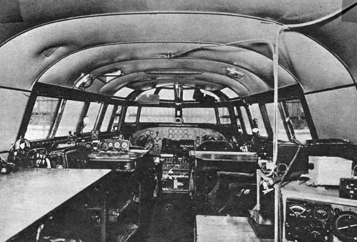


 The Saab B 17 is a light bomber/dive bomber and reconnaissance plane with two seats, a single engine and a single tail, whose design bears a close resemblance with the Mitsubishi Ki-30 “Ann”, the Mitsubishi Ki-15, the Vought OS2U, and the Curtiss SB2C Helldiver, especially with the elongated shape of the main airframe and equally elongated windscreen of the cabin (as well as the same cockpit), which occupies most of the superior area of the airframe and it is fully incorporated in the fuselage. The wing is a mid-wing (cantilever) of trapezoid shape with a remarkable characteristic: where the retractable landing gear, which was covered with streamlined fairings, was placed, the rear part of the wing was divided. From the fuselage to the place of the landing gears, it was straight; from the landing gears area to the wingtip, it was angled. The forward area of the wing was straight, and the wingtips were rounded. The wing, from a frontal perspective, was slightly angled upwards from the landing gear area to the wingtip. It was also a reinforced wing to allow it to deal with the high stress by dive bombing missions.
 The design of the B 17 is similar to other aircraft used in WWII by other countries, meaning it has the typical ‘WWII style’. But instead of being the average WWII design, the B 17 has some remarkable and particular characteristics. The airplane is an all-metal airframe, with the bow having a cylinder shape thanks to the radial engine and the stern is topped off with the tail, and the overall airframe being elongated with a sort of conical shape. The airplane is also a semi-straight leading-edge wing airplane, but the wings also have a particular characteristic. In fact, the wings have a ‘divided’ shape, with the area of the landing gear being the dividing point. First, from the fuselage to the landing gear, the leading-edge is straight while the rear-edge is also straight, having two ‘dog-teeth’ that mark where the rear area of the fairings are located. Second, from the landing gears to the tip of the wings, the leading-edge of the wings are straight as well, but the rear-edges are angled, making this area of trapezoid shape. The tips are rounded. The wings also have a divided shape from a frontal perspective, with the landing gear being also the dividing area. From the fuselage to the landing gear area, the wing is straight. However, from the landing gear to the tip of the wings, it is angled upwards, similar to the Ju-87 Stuka or the Douglas SBD ‘Dauntless’, only that the angle is not as wide. The wing, furthermore, is installed in the middle of the fuselage (cantilever), also being reinforced. Such reinforcement can be seen through its thickness. The horizontal stabilizers are also of trapezoid shape, with the control surfaces per se having an inwards angle at the tip of the surface. The tail has a similar shape with the rudder occupying most of the surface and having also an inwards angle near the tip. Both horizontal and vertical stabilizers have an equally rounded shape.


