World War 1 saw the introduction of aircraft to the battlefield. Initially, crude wood framed canvas covered aircraft were deployed in light reconnaissance roles. However the combat potential of aircraft was quickly realized and military aircraft development bureaus were established to oversee the development of planes designed for attack, fighter, bombing, and reconnaissance roles.
In the beginning, pilots were armed with conventional handheld firearms to take potshots at enemy scout planes. However research and development of heavier armed planes soon saw the introduction of light machine guns and many methods were attempted to find a way for pilots and gunners to accurately aim. After much trial and error with different configurations, it became clear that the easiest solution was to affix weapons directly to the fuselage or wing of the plane, rather than attempt to manually aim weapons independent of in-flight movement of the aircraft.
The earliest crude iterations of this setup included the Morane Saulnier which mounted a machine gun directly on the centerline of the fuselage, directly in front of the pilot for relative ease of aiming. However this presented a problem of the bullets hitting the propeller. Initial crude solutions included mounting reinforced steel armor to the propeller to deflect bullets that struck the propeller.
The introduction of the interrupter gear finally solved this problem by a direct mechanical synchronization between the engine’s rotation and the timing of the gun’s firing. This development meant that more robust armaments could be used without the need for a specialized heavy propeller.
As the war raged on in Europe, the British, French, and the Germans engaged in an air arms race driven by constant experimentation and design fads. Even the slightest edge in speed, armament, or maneuverability could make the difference in air superiority. Pilots’ skills were also constantly put to the test, attempting to push their wood-framed contraptions to the breaking point, often with tragic results.
The strange looking DFW T28 Floh. [DFW Aircraft of WWI]The DFW T28 Floh (Flea) was an early biplane fighter designed for use by the German Empire. To get an edge over then current monoplane fighters, the T28 was designed with aerodynamics and speed in mind. The result was an aircraft that looked straight out of a cartoon. Despite its appearance, the aircraft performed well during testing, maxing out at 112mph (180 km/h). Although its speed was good, its large body and the placement of the wings reduced visibility for the pilot, making landings with the craft difficult. This was enough for officials to decline production of the type despite its respectable top speed.
History
In times of emergent technology, it goes without saying that many new endeavors are tested out. Many of these may seem strange to us now, but something odd looking to us could have been revolutionary for the time. This was no exception for aircraft in the First World War. Many different ideas were tested in the name of advancing aerodynamics. Some of these would end in blunders while others would be influential to aircraft design. A curious case of attempted aircraft advancement was the DFW T28, a plane that pushed records for speed, while looking downright comedic.
A frontal view of the Floh during taxxiing, the pilot had to stand up to even see while doing this. DFW C.Is are visible in the background. [DFW Aircraft of WWI]The Deutsche Flugzeugwerke (DFW) was a German aircraft manufacturer formed in 1910 that license-built French aircraft before the war. During the early years of the First World War, they would design and produce a number of two-seater aircraft types, both armed (C-Type) and unarmed (B-Type). No work was done on a fighter aircraft by DFW at the beginning of the war. Fighter aircraft weren’t as common by this point in the war as they would soon be known, with most types in production being German Eindecker (monoplane) designs like the Fokker E.I. Very few actual biplane fighters (D-Type) had been developed at this time, aside from a prototype or two. Despite this, the Eindecker showed its effectiveness and led to a period of time in 1915 where the air was dominated by the Germans, known as the “Fokker Scourge” to the allies.
Herman Dorner with his Floh. [DFW Aircraft of WWI]In mid 1915, a new head engineer, Dipl-Ing (Engineer) Hermann Dorner was appointed at DFW. Dorner was a German early aviation pioneer in the 1900s and 1910s, building gliders and powered aircraft alike. He had formed his own aircraft company in 1910, but due to poor business decisions on Dorner’s end, the company would be liquidated in 1913. He would go on to work as a teacher at the Adlershof flight school, as well as working for the Deutsche Versuchsanstalt für Luftfahrt (German Research Institute for Aviation) before finally being employed by DFW during the war. After joining DFW, Dorner began working on a new fighter aircraft project. Dorner took issue with the Eindeckers in service at the time, particularly relating to their speed. Despite their effectiveness, all of the Fokker Eindeckers built (E.I-E.IV), could not attain a speed faster than around 87mph (km/h). With newer Allied machines on the horizon, this speed wouldn’t give the Eindeckers an edge forever and a replacement was needed.
Dorner had speed in mind with his fighter design. His vision had the aircraft streamlined for aerodynamic flow. Overall the aircraft would be small and light in construction to reduce weight. Work began on a prototype of Dorner’s fighter in late 1915 at DFW’s facility in Lubeck-Travemunde. This facility primarily served as a flight school for DFW, and wasn’t their main factory. The construction of the aircraft, now known as the DFW T28 Floh, was supervised by Theo Rockenfeller at the plant. The final T28 looked like it flew straight out of a cartoon, possessing a very tall fuselage with small wings. This proportional difference made the aircraft appear more like a caricature than a combat aircraft of the time period. Despite its design, the aircraft was still designed for speed, and would have a 100hp (74.5kW) Mercedes D I engine, which was completely enclosed in the fuselage. Armament would be a single machine gun mounted in front of the pilot. The T28 would take flight shortly after its construction, but the exact date is unknown. The design choices of the aircraft to make it fly faster worked well, as it was able to achieve a top speed of 112 mph (180 km/h), which was extremely impressive for the time period. However, its design wasn’t perfect and the choices made to improve speed negatively affected other aspects of the aircraft, in particular, its landing characteristics. The tall profile of the craft, the location of the upper wing, and the placement of the pilot’s position, gave him a superb view above the plane but was severely restricted frontally and below. The prototype Floh would be damaged due to this reason upon landing on its first flight, due to the pilot misjudging his height, as well as having a fast landing speed. This issue also affected takeoff, as the high placement of the pilot required him to stand up during taxiing to see. The design was reworked a few times after its first flight, mainly with improving the tail surfaces. Despite achieving the speed Dorner wanted, the military officials showed little interest in the design, with some sources citing that it was just too fast for the military. Further work on the aircraft was stopped after this. Exactly what happened to the aircraft after being declined for production is unknown, whether it was simply scrapped or if it was continually used at DFW’s facilities for training and testing are possible theories. Many prototype German aircraft of the First World War would go on to serve as trainers for their various companies once production declined. The facility the T28 was built served as a flight training school for DFW after all.
Design
Rear view of the aircraft. [DFW Aircraft of WWI]The DFW T28 Floh was a biplane fighter designed in 1915 to supersede then in use Eindecker fighters. It had a length of 14ft 9in (4.3 m), a wingspan of 20ft 4in (6.2 m) and a height of 7ft 6in (2.3 m). The aircraft had a tall, flat sided fuselage constructed of wood. The fuselage would be sleek and rounded in design to reduce drag. Buried in the fuselage was a 100hp (74.5kW) Mercedes D.I engine. The aircraft had a large wooden propeller, with a relatively small landing gear mounted far forward with two wheels almost at the nose of, accompanied by a landing skid at the end of the tail. The short wings were fabric covered with wooden ribs. The wings themselves were single bay, meaning only one pair of support struts between the upper and lower wing. The upper wings were placed in a way that restricted the pilot’s vision downward and forward. Behind the wings and engine in the fuselage sat the pilot. Two cutouts were made into the left side of the fuselage for the pilot to climb up into the cockpit. Toward the rear of the fuselage the tail would taper. At the end were the horizontal and vertical stabilizers. The vertical stabilizer itself acted as the rudder and was completely movable. The elevators were originally the same width as the horizontal stabilizers but these were modified later into testing to be wider to increase performance.
For armament, a single synchronized machine gun was fitted in front of the pilot.
A side view of the Floh, its strange proportions are clearly evident. [DFW Aircraft of WWI]
Conclusion
The T28 Floh was a very interesting concept for a fast fighter at a time where biplanes weren’t yet used in such a role in German service. Its design choices might seem strange now, but they meshed together to create a truly fast aircraft of the time. The design however, was troubled by problems that would see it fail to enter widespread production, and eventually more conventional biplane fighter designs would enter service less than a year after the Floh was built. DFW would eventually produce several conventional biplane fighter prototypes later on in the war in 1917 and 1918, but these all performed very poorly. Aside from having structural problems and a poor field of view, the last of these, the D.II, was in fact slower than the Floh.
Dorner would continue working for DFW designing aircraft. His next project after the Floh would be the much more successful DFW R.I Reisenflugzeug (Giant Aircraft), which would first fly in 1916. Dorner, however, wouldn’t stay with the company to see the completion of this project and its success, as he would move to Hannover Waggonfabrik AG in October of 1916 as their chief designer. Here he would design several successful two-seater aircraft, the CL.I through CL.IV, which saw widespread use during the war. He would survive the war and continue working on civil air projects.
Interestingly, this wouldn’t be the only type of aircraft to share this strange design idea during the war. The Austro-Hungarian Lohner Type AA fighter of 1916 also had similar proportions, with a very tall body and small wings to increase speed. This aircraft would have poor flight performance and would be heavily reworked to resemble the more standard biplanes then entering service.
Variants
DFW T28 Floh – The T28 was a small fighter designed to outperform Eindecker aircraft in terms of speed. 1 was built and tested.
Operators
German Empire – The T28 Floh was designed for use by the German Empire but wasn’t adopted for service.
DFW T28 Floh Specifications
Wingspan
20 ft 4 in / 6.2 m
Length
14 ft 9 in / 4.3 m
Height
7 ft 6 in / 2.3 m
Wing Area
162 ft² / 15 m²
Engine
1x 100 hp (74.5 kW ) Mercedes D.I engine
Propeller
1x 2-blade wooden propeller
Weights
Empty
926 lb / 420 kg
Loaded
1,433 lb / 650 kg
Maximum Speed
112 mph / 180 kmh
Crew
1 pilot
Armament
1x Machine Gun
Gallery
The DFW Flea – Illustration by Carpaticus
Credits
Written by Medicman11
Edited by Ed J. and Henry H.
Illustrations by Carpaticus
Sources
Green, W. & Swanborough, G. (2002). The complete book of fighters : an illustrated encyclopedia of every fighter aircraft built and flown. London: Salamander.
Herris, J. (2017). DFW Aircraft of WWI : a centennial perspective on Great War Airplanes. Charleston, SC: Aeronaut Books.
German Empire (1917)
Heavy Bomber Prototype- 4 Built
Linke-Hoffman R.I 40/16 side view. [The German Giants]The Linke-Hofmann R.I was an experimental heavy bomber developed by the German Empire in 1917. The R.I would be unique, as one of the first prototypes to be constructed mostly out of a translucent material known as cellon, with the idea that it aircraft would be harder to spot. Unfortunately for the designers, cellon is highly reflective and ended up making the craft a much more noticeable target. After the failure with cellon, more work continued on the prototypes, now of normal fabric skinned construction. Due to poor performance caused by several design choices, the type was not mass produced and was subsequently cancelled.
History
A drawing of the R.I done by Linke-Hoffman. Notice the 3 gun positions. [German Aircraft of Minor Manufacturers Volume II]During times of war, it is not too uncommon for companies, factories and other industrial firms to be drawn into the war effort and end up producing materials that are as far away from their specialty as possible. Sometimes, this can end in a surprise success or a total blunder. This was no exception in the first World War for the German Empire. The concept of the military airplane had seen its first successes early in the war,and the need for aircraft was on the rise, but a major problem came in the fact that there were few dedicated airplane companies in Germany at the time. Thus, the Empire would call upon many of its industrial manufacturers to begin designing and producing aircraft, even if they were not familiar with working in that field. Linke-Hofmannn would be one such company.
3-Way drawing of both versions of the R.I [The German Giants]Linke-Hofmann, sometimes misspelled Linke-Hoffman, was founded in 1912 and was a manufacturer of railroad components, mainly locomotives and rolling stock. In early 1916, the company would enter the field of aviation by using their factories for aircraft repairs and for license built construction of aircraft. Some aircraft types they built under license were the Roland C.IIa, Albatros C.III, Albatros C.X and the Albatros B.IIa. At the same time, Linke-Hofmann was also awarded a contract to produce their own aircraft. The first of their home built aircraft would be an R-Plane type or Riesenflugzeug (giant aircraft), which was the designation given to the largest multi-engine bomber aircraft of the Empire. Linke-Hofmann’s R.I design would be a strange looking machine. Its fuselage was short and tear-drop shaped to streamline the design . Each pair of wings would be mounted extremely high and low on the fuselage in an attempt to increase lift. Four internal engines would be connected to four propellers, two in pusher configuration and two in puller configuration. Most interestingly, a majority of the tail of the aircraft would be made out of a material called Cellon. Cellon (Cellulose Acetate) is a translucent, plant-based material similar to film that was tested on several German aircraft in WWI, swapping out the normal fabric. The idea behind having the airframe covered in such material was that it was thought to make the aircraft harder to see. In addition to the Cellon, the R.I also had a very large cockpit with a number of windows to give much better visibility. Many of these design choices were made as it was thought they would make the design perform better in the long run, but they would ultimately lead to its downfall.
The R.I 8/15 under construction. The Cellon is clearly visible [German Aircraft of Minor Manufacturers Volume II]The Cellon tail of 8/15 [German Aircraft of Minor Manufacturers Volume II]
The completed R.I 8/15
Work began on the first R.I in the later months of 1916 under Chief Engineer Paul Stumpf, who previously worked for the AEG aircraft works. The first R.I was completed in early January of 1917 and was named the R.I 8/15. Testing of the aircraft began, but its first flight was delayed due to the unconventional steel tires coming apart during taxiing attempts. Improved versions of the tires were built that were much more stable than the first. Shortly after, the R.I 8/15 would fly for the first time from the Hundsfeld Airfield near Breslau, but the exact date is unknown. Early test flights showed the design was flawed and as time went on, performance began to suffer, although the exact reason was not known. Noticeably, the wings seemed to be the root cause of the lag in performance. The aircraft’s controls would occasionally become heavy and unresponsive, resulting in a partial loss of control. To amend this to some degree, several additional struts were added to the main wings, but this would not save the aircraft from disaster. On May 10th 1917, during its 6th test flight, two of the wings on the R.I 8/15 would collapse mid-flight and the aircraft would slam into the ground at full speed. Remarkably, all of the crew of the aircraft would survive, but the airframe itself would be destroyed in a blaze of fire caused by the crash. Unfortunately, 1-2 ground crew would die from the flames while trying to put them out.
The destruction of the 8/15 would force Linke-Hofmann to look into designing an improved model. At this time, many of the design choices Linke-Hofmann made with the aircraft would show how ineffective and even detrimental they were. The wings themselves were the root cause of the crash, as they were not stable nor very well supported. The Cellon material, which was thought to make the aircraft invisible, actually ended up doing the exact opposite, as the material was highly reflective, especially while the aircraft was airborne. Cellon itself also was not the most stable material to make most of the tail section of the aircraft out of, as the material itself could easily bend and warp during rough weather. Even when the material worked as needed, it aged to a yellow color that would remove the translucency. Even before the aircraft took flight, Linke-Hofmann would be criticized for making an aircraft mostly out of the little tested material. In order to amend these issues, the Idflieg ,,the Imperial organization that handled aircraft development, ordered several improved models to continue the development of the type, as the 8/15 had crashed before most of the evaluation had completed. Linke-Hofmann would then begin construction on the improved models, serial numbers 40/16 through 42/16. These improved variants on the R.I attempted to fix many of the issues that plagued the 8/15. The wing structure was redesigned to be significantly more stable, with additional struts forming an overall better design. Most of the Cellon in the aircraft had been replaced with standard fabric, with only a few small patches of the tail containing it, likely to serve as observation windows. The landing gear was also heavily improved, something the Linke-Hofmann Engineers were quite proud of. Lastly, the new airframe was also built to accommodate three positions for machine gunners. These small improvements mended these few issues, but the aircraft’s design was still riddled with flaws.
40/16 in flight. [German Aircraft of Minor Manufacturers Volume II]Details regarding the history of the improved variants are, unfortunately, not well known. It is unknown exactly when the R.I 40/16 first flew or when it was even built, but the handling of the aircraft had been significantly improved upon over the 8/15. Maneuverability was especially stated to be superb compared to the older model, but its general performance was still considered to be unsatisfactory. Landing the aircraft was stated to be terrible due to the high location of the pilot and the slow landing speed.
The crashed 40/16 after a taxiing accident. [German Aircraft of Minor Manufacturers Volume II]During one landing attempt while testing the 40/16, the test pilot misjudged how close he was from the landing strip due to the height of the aircraft and damaged the landing gear. Due to the teardrop shape of the aircraft, the entire thing went nose down into the ground, crushing the entire cockpit section. It is unknown if anyone was killed or injured during the crash, but no attempt was made to repair the aircraft afterwards and it was likely scrapped. Details on the 41/16 and 42/16 are even more lacking. Some sources claim they were never completed, while other sources state they were complete and ready for inspection before the program concluded. 41/16, in particular, has virtually no information or photos of the aircraft, but two photos exist of a finished 42/16 sitting outside the Linke-Hofmann factory in Breslau.
Design
A direct frontal view of 40/16. The unique engine-propeller arrangement can be seen clearly, as well as the tall profile of the aircraft. [German Aircraft of Minor Manufacturers Volume II]Pilot’s position of the R.I [German Aircraft of Minor Manufacturers Volume II]The Linke-Hofmann R.I was a four engined R-Type aircraft with a large teardrop-shaped fuselage covered in fabric. The fuselage was designed in such a “whale” configuration to contain its engines and reduce drag, but this was only ever tested on smaller aircraft and likely detrimentally affected the R.I. The front of the aircraft was divided into three different floors. The first floor contained the pilot’s position and the wireless station for communication. This floor had extensive glasswork to provide a good view around the front of the aircraft. The large amount of glass used in the cockpit only helped during clear weather as, during rain or if illuminated by a searchlight, it would cause visibility to suffer from light reflection and condensation.
Engine Room containing the four Mercedes D.IVa engines
The second floor contained the four Mercedes D.IVa engines. The third and lowest level contained the bombardier’s station and four internal fuel tanks. The tail of the R.I differed between the two variants. On the earlier 8/15, the tail was composed mostly of Cellon, while on the later 40/16, it was covered in fabric. The tail of the aircraft had a biplane horizontal stabilizer and three vertical fins for vertical stabilizers. The two additional fins vertically and the upper wing of the horizontal stabilizers were used as control surfaces on top of the conventional placement of said control surfaces. The wings of the aircraft were placed high and low on the aircraft, with the fuselage height directly separating each wing. Only the upper wings had ailerons fitted. The wings on the 8/15 were actually the lightest of any R-Plane built, which was a likely factor in its crash. The 40/16 had improved and more stabilized wings compared to its predecessor. The aircraft originally was planned to have four propellers, two in tractor and two in puller configuration but this design aspect doesn’t appear to have ever left the drawing board. Instead, only two were used in tractor layout. The engines powered the propellers in a very unique way. Each side of the aircraft had one propeller, which was connected to a pair of engines via outrigger frames and powered through a drive shaft connected to a bevel gear. Each pair of engines powered one side. This was done so that, in the event one of the engines was disabled through either malfunction or combat, the propellers would still have power going to them. A disabled propeller would begin windmilling, or rotating without power, and cause significant drag. On larger aircraft, this would seriously alter performance and cause the aircraft to lose speed and airflow due to drag. This complex system was put into place to prevent this from happening.
R.I 40/16 outside of the Linke-Hofmann factory. [The German Giants]No armament was carried aboard the R.I, but several proposals were made. Three machine-guns of unknown type and caliber were to be located at three positions around the aircraft. Two were located on the tallest point of the body, with one facing forward and one facing backward to cover all angles. The third gun position was located in the middle of the aircraft, with two open windows on each side to provide maximum firing range to each side. Given it was an R-Plane, the R.I would have used bombs had it entered mass production, but it’s loadout was never addressed, since the type was considered a failure.
Conclusion
The only two images of the Linke-Hoffman R.I 42/16 near the Linke-Hoffman factory [The German Giants]With the destruction of two aircraft and the type severely underperforming to expectations, the Idflieg lost their faith in Linke-Hofmann’s R.I program and it was promptly cancelled before January 1918. The 41/16 and 42/16 were most likely scrapped before the end of the war. The type was riddled with flaws from the beginning due to the strange decisions made by Linke-Hofmann in designing their first aircraft. Despite their failure at the start of their aircraft manufacturing career, Linke-Hofmann would use the experience learned from the R.I to create an improved and much more traditional looking R-Plane aircraft, the R.II.
Variants
Linke Hofmann R.I 8/15 – First version of the R.I. This version’s tail and rear fuselage were constructed of the transparent material Cellon.
Linke Hofmann R.I 40/16 – Improved version of the R.I 8/15. This type had many slight modifications, such as a better wing structure, a more stable landing gear, and was no longer constructed of Cellon. 3 of this type were built.
Operators
German Empire – The Linke-Hofmann R.I was an R-type aircraft meant to be used in the heavy bomber role for the German Empire. However, due to poor performance, the type was never mass produced or sent into service.
The Linke Hofmann R.8/15 – Note the extensive use of transparent cellon for the aft portion of the fuselage.The Linke Hofmann R.40/163-Way drawing of both versions of the R.I [The German Giants]
Credits
Written by: Medicman11
Edited by: Stan L. & Henry H.
Illustrations by Ed Jackson
Sources
Kosin, Rüdiger. The German fighter since 1915. Baltimore, Md: Nautical & Aviation Pub. Co. of America, 1988. Print.
Herris, Jack. German Aircraft of Minor Manufacturers In WWI Volume 2: Krieger To Union, Columbia, SC: Aeronaut Books, 2020. Print.
Haddow, G. W., and Peter M. Grosz. The German giants : the German R-planes, 1914-1918. London: Putnam, 1988. Print.
German Empire (1915)
Reconnaissance Aircraft – 267 Built
A Roland C.II in flight. [Roland Aircraft of WWI]The Roland C.II was a reconnaissance aircraft built by LFG Roland in 1915 as a new and innovative design. The type would see widespread use by the German Empire and, thanks to its highly advanced form, became the fastest and most maneuverable of its type when it was introduced. Overall improvements on the aircraft were done throughout the war to strengthen its performance, but by the end of the war, much more advanced aircraft had been deployed and made the Roland obsolete. The C.II was relegated to a training aircraft until the end of the war, when all were scrapped.
Development
In early 1915, the Luftfahrzeug Gesellschaft (L.F.G.), also known as Roland to avoid confusion with a similar sounding design firm, began building several Albatros aircraft under license. These aircraft were the Albatros B.I, B.II and the C.I, which were considered some of the most advanced in terms of aerodynamics for the current times. Around the same time, Dipl.-Ing. (Engineer) Tantzen would join Roland as chief designer. With Tantzen as the chief designer and their experience gained from license-building aircraft, Roland would begin designing a new and original plane, the C.II.
Work began on the C.II (C-types were two-seat armed aircraft) sometime in mid 1915. The C.II would have a very rounded, aerodynamic fuselage design, similar to the Albatros D.III fighters of the following year. The fuselage was created in a unique way, called Wickelrumpf (Wrapped body). Wickelrumpf involved using layers of veneer strips that were wrapped around a simple wodden frame. The shells created were then glued together around the wooden frame of the C.II and strengthened with fabric, making a very streamlined and sturdy fuselage. This whole process was an early attempt at monocoque construction, which involved having a shell built around a frame. However, the Wickelrumpf technique on the C.II used two stringers for the frame, a feature true monocoque aircraft don’t have. Like the fuselage, the wings were also designed to be very aerodynamic. Instead of having the wings connected with multiple spars and bracings, as was common with aircraft of the time, the wings of the C.II would be connected via a single wooden strut in a single bay wing.
The C.II prototype on October 24th, 1915, only hours before its disastrous test flight.
Before a prototype was completed, a C.II fuselage was mounted on a railcar for aerodynamic testing and other experiments. The train would swiftly go down a straight track between the cities of Schoneberg and Juterbog and data would be recorded on the aircraft. The first prototype C.II was completed in October of 1916 and its first test flight would happen between the 24th and 25th. This test flight would end in misfortune, with the D.III engine failing mid flight, resulting in a crash and subsequent damage to the aircraft. The prototype was quickly repaired and flying, with a second prototype completed soon after. In the test flights, it was found that, thanks to its aerodynamic design and powerful D.III engine, the C.II’s speed was extraordinary, surpassing all of the current C-type aircraft then in use. With such a feat, a production batch of 50 aircraft were ordered on December 23rd, 1915. Testing continued and it was found that the wing cells were slightly unstable, so an additional drag wire was added for stabilization. After this change was added to the design and prototypes, production of the type continued and, by March 7th, 1916, the first of the production aircraft were ready to be sent to the front.
Design
The last production batch of C.IIs [Roland Aircraft of WWI]The interior frame of the C.II. This would be covered by the Wickelrumpf shells. [Roland Aircraft of WWI]The Roland C.II was a two seat observation biplane. The body of the C.II was aerodynamic in shape and had a plywood frame, with the outer shell created via Wickelrumpf and made of veneer strips glued together and supported with fabric. Wickelrumpf produced a semi-monocoque fuselage. The body would have two seats, one for the pilot and one for an observer. On the sides of the fuselage were two pairs of celluloid windows for the observer to use. On several occasions, flight crews would paint curtains onto them. The windows themselves were modified by the crews to open by sliding backwards or downwards, but this was not a standard feature. Above the pilot’s position was a roll cage designed to prevent the pilot from being crushed in the event of a roll over on the ground. The initial design of the cage was circular but, once the frontal Spandau was added, the cage had to be redesigned and became more triangular in shape. No measure was given to protect the observer. The C.II used a Mercedes D.III engine mounted in the nose and driving a wooden propeller. The first two cylinders were exposed to the elements. The area surrounding the engine was the only part of the aircraft to have metal plating. Certain plates were hinged to allow for maintenance to the engine. For exhaust, the initial models used the “ocarina” style pipes, but later models would change between the ocarina style and others. The engines would have two ear radiators on each side of the craft. These protruding radiators obstructed airflow and caused drag. The tailfins were wooden and fabric covered. The control surfaces were made of steel tubes and covered in fabric. The tailfin was enlarged after the June 1916 batch to increase stability.
A sight all too common of the C.II. Due to its poor downwards visibility, Pilots had trouble landing the aircraft. [Roland Aircraft of WWI]The wings of the aircraft were made of wood and covered in doped fabric as was conventional at the time, with the control surfaces being made of steel tubes and also covered in doped fabric. The ailerons were originally in the lower wing but, starting with the C.IIa, these would be located in the upper wing. The wings themselves were the exact same length, shape and chord. Unique I-struts connected the wings together. The I-struts were of plywood construction and would have interior bracings in the shape of an X. The C.II would have a landing gear connected to the aircraft with v-shaped connectors. At the rear of the aircraft would be a landing skid.
Mid Production C.II [Roland Aircraft of WWI]For armament, the C.II initially only had a single Parabellum 7.92 mm for the observer to use. After the first 50 aircraft, a forward firing synchronized Spandau 7.92 mm was added for the pilot. If needed, four bomb racks could be fixed to the underside of the wings to carry small bombs. The aircraft also carried several flares. A radio could also be carried on the aircraft and used by the observer. This was powered by an airscrew-powered dynamo located near the landing gear.
The “Walfisch” In Action
Otto Czernak’s C.II. This aircraft was modified with a rudimentary machinegun mount and an input system for the observer to request certain flight movements. [Roland Aircraft of WWI]The Roland C.II arrived on the frontline in late March of 1916 and the effort put into its aerodynamic design was noted almost immediately. The C.IIs were the fastest aircraft used by the Luftstreitkräfte (German Air Force) at their introduction, outpacing all of their operational aircraft and almost all opposing Allied aircraft, only being superseded by a handful of Allied fighters. Because of its impressive speed, the Roland C.II was flown in special groups, as other two seater C-type aircraft could not keep up with the type. The Roland C.II was initially used as a reconnaissance plane, with the second crewman acting as the observer, but its speed allowed it to be used on escort duties as well. Despite its good speed, however, the C.II was not without its flaws. In the observer role, thanks to the crewmen being seated above the body, visibility above the plane was superb, but visibility in front of the aircraft was lacking, and visibility beneath the aircraft was poor. An attempt to fix this early on, before production began, was placing cutouts in the base of the wings, but this solution still do not provide adequate visibility. This flaw became fatal later on, once enemy pilots learned of this massive weak spot, as they would now dive beneath a C.II, then fly upwards towards it, firing their guns while the Roland crew had no means of detecting threats from that angle. This visibility issue also made landings especially dangerous, as the pilot had difficulty calculating how close the ground was. Aircraft of the time were well known to have difficulty upon landing, but the Roland C.II exhibited worse than average landing performance due to the visibility issue. Maneuverability and stability of the C.II was also lackluster at times and would need improvement.
Initially, the Roland C.II only had a single Parabellum 7.92 mm machine gun for the observer to use. The first fifty of these aircraft would have this small armament. Many of the pilots found this weak armament lacking. One pilot in particular, Lt. Otto Czernak of Schusta 28, would fix this issue on his own. He would rig up a forward firing apparatus for another Parabellum machine-gun that would allow the pilot to fire. Due to the propeller and machine-gun not being synchronized, the rig placed the gun well above the rotating radius of the propeller, making the rig very tall. Czernak’s own plane was modified in other ways as well, having a unique input system for his observer that would allow the 2nd crewman to communicate to Czernak to maneuvering instructions. No other C.II would have this system. After the first fifty aircraft, all C.II’s would have a synchronized Spandau machine-gun for the pilot to use. This gave the C.II some dogfighting ability, which is how it would end up being used for escort duties, along with its excellent speed.
A Linke-Hoffman produced C.IIa(Li). This particular aircraft has bomb racks installed. [Roland Aircraft of WWI]At some point, either during its career or while it was still being developed, the C.II was given the unofficial nickname of Walfisch (Whale). The origin of this name has been told many times but there is no concise point that has been confirmed. The most common of these origins is said to have come while it was still in development, from a German official observing the type. Another reason could have been its overall round shape and how the early models were painted a silver-white color. Nonetheless, the name stuck around. The name Walfisch did not seem to have any negative connotation for its pilots, as many of them would paint fish or shark faces on their aircraft. Some would even paint scales. The previously mentioned Otto Czernak would paint a fish face onto his aircraft. This tradition was seen throughout its lifespan, even after the later two-toned camouflage models were introduced with green and brown paint.
A production of 24 aircraft, after the initial batch, with the modified machine-gun was ordered in March of 1916. Another batch of 45 aircraft was ordered in April. However, the batch of Roland C.IIs after this set would aim to fix many of the stability issues found with the aircraft in the field. The tailfin was enlarged to improve flight performance. The wings were shortened and the I struts were moved inward to compensate for the wing flexing. These made the wings much more structurally sound. This reworked design of the C.II was known as the C.IIa and testing of the type began in April and May of 1916. The type would be sent to the frontline by the summer. All C.II aircraft after this point would be of the C.IIa model. A batch of 19 C.IIa was ordered in April of 1916 and another batch of 36 C.IIa was also ordered, but with the ailerons in the upper wing. All aircraft after this would have the ailerons this configuration. A batch of 40 C.IIas was ordered in June of 1916 and would have a larger vertical fin to improve stability.
Production C.II [Roland Aircraft of WWI]Most of the production Roland C.IIs were flying by the mid summer of 1916. The C.II was used extensively at the Battle of the Somme, where it was used in large numbers for recon and escort duties. On the second day of the Battle of the Somme, June 2nd, the soon-to-be-famous Albert Ball would go on a sortie in a Nieuport scout aircraft. While flying, his squadron would encounter 6 Roland C.IIs on patrol. The Allied squadron would begin their attack, while the Roland formation scattered. Ball was able to catch up to one and shoot it down, causing the C.II to plummet near the Mercatel-Arras road. This would be the first aircraft Ball completely destroyed in flight (There were several confirmed victories before this, but this was the first confirmed complete destruction of an aircraft). Many of Ball’s early kills were Roland C.IIs. Ball himself went on to compliment the C.II, stating it was the best aircraft the German’s had at the time, with a good defense to compliment its speed.
A C.IIa in two tone colors. This particular aircraft has been decorated by its crew, including painted on curtains over the celluloid covers and a shark mouth. [Roland Aircraft of WWI]The Roland C.II was continually used through the rest of 1916. By summer, the Linke-Hofman company would begin license building C.IIs. An initial batch of 16 aircraft was ordered. The aircraft built under license were known as C.IIa(Li). In July of 1916, a batch of 40 aircraft was ordered to be produced by Linke-Hofman. This would be the last batch of C.IIs built and would be sent to the front in the beginning of 1917. By this time, however, the C.II had lost its performance edge. The Allies had fielded newer and improved aircraft that were able to easily keep up with the C.II, and the Germans had also produced newer aircraft that performed better. The C.II was instead returned from the front lines and used as a trainer for the C-type in flight schools. The C.II would perform this duty until hostilities ended in 1918. The fate of the remaining C.IIs is unknown, but they were most likely scrapped. No aircraft survive to this day.
The Roland C.III: A Derivative Design
The Roland C.III. It is apparent its design is based off of the C.II. Very little is known about this aircraft. [Roland Aircraft of WWI]In mid-1916, a derivative design of the C.II emerged; the Roland C.III. The C.III shared many of the same design features of the C.II, such as a two-seat aerodynamic body with two windows on each side for observation purposes. However, most of the similarities stop there. The C.III was designed to use the more powerful 200 hp (149 kW) Mercedes D.IV engine over the C.II’s D.III. Based on the few pictures available, the prototype C.III appears to still use a D.III engine, most likely to test the airframe before the larger engine was placed. To compensate for a stronger engine, the wings of the C.II were made larger. The wings themselves were also reworked. Instead of having single bay wings with flat strut connectors, like the C.II, the C.III instead had the standard two bay wings typical of aircraft of the era. This was most likely done as the single struts of the C.II happened to obscure the vision of the frontal windows. The tail design of the C.III also differed from the C.II. Very little is known of the C.III outside of these few details, including whether or not it even flew or any further testing. The single C.III prototype was lost when LFG’s facility in Adlershof was destroyed in a fire on September 6th, 1916. This incident is cited to be caused by sabotage from British Special Forces. After the loss of the prototype, no further work on this type was done.
Conclusion
A lineup of several early C.IIs [Roland Aircraft of WWI]At the time of its introduction, the C.II was one of the most advanced aircraft Germany had. Its powerful engine and aerodynamic construction allowed it to outperform most of its opposition. As the war continued, more advanced machines eventually outpaced the Roland C.II. The aircraft did manage to influence other companies to attempt more aerodynamic designs. Roland would continue building planes, including newer C-types (C.V and C.VIII) and fighter types, both of which would use Wickelrumpf. Two other aircraft were built off of the C.II’s design, the D.I fighter and the WD floatplane. Despite continuing to make newer aircraft, none of Roland’s designs would ever garner the same fame as their “Walfisch”, and it would remain their most iconic design of the war.
Variants
LFG Roland C.II Prototype – The prototype model of the C.II differed from the production version in several ways. Notably, it only had one set of windows. Two of these were built.
LFG Roland C.II – Standard model for the Roland C.II. After the initial batch, all aircraft would use a synchronized machine-gun in the nose.
Otto Czernak’s LFG Roland C.II – A modified early production C.II used by Otto Czernak of Schusta 28. It had a makeshift machine-gun mount and a unique input system for the observer to request movements from the pilot.
LFG Roland C.IIa – Later modified model of the C.II, had improved wings and a larger tailfin.
LFG Roland C.IIa(Li) – Designation given to C.IIa planes license-built by Linke-Hofman.
LFG Roland C.III – Derivative aircraft based on the C.II. Heavily reworked the wings and was given a Benz B.IV engine.
Operators
German Empire – The Roland C.II served as a reconnaissance aircraft and an escort aircraft in several squadrons of the Luftstreitkräfte from 1916 to 1918
LFG Roland C.II Specifications
Wingspan
33 ft 10 in / 10.33 m
Length
25 ft 3 in / 7.7 m
Height
9 ft 6 in / 2.9 m
Mean Aerodynamic Chord
4 ft 11 in / 1.5 m
Wing Area
91.7 ft² / 27.96 m²
Engine
160 hp (119.3 kW) Mercedes D.III 6-cylinder inline engine
Roland C.II PrototypeRoland C.II Schusta 28 – Lt. Otto Czermack Note the forward firing Lewis Gun mounted high to clear the propeller arc.Roland C.II – Black Stripes over Pre-Production PaintRoland C.II featuring a Shark MouthRoland C.IIa – Note the Larger RudderRoland C.III Prototype
Credits
Article written by Medicman
Edited by Stan Lucian & Ed Jackson
Illustrations by Ed Jackson
Herris, Jack. Roland Aircraft of WWI : a centennial perspective on Great War Airplanes. Charleston, SC: Aeronaut Books, 2014. Print.
Gray, Peter L., and Owen Thetford. German aircraft of the First World War. London: Putnam, 1970. Print.
Robert Macfie piloting the biplane ‘Circuit’ at Brooklands, 1911 [Flight Magazine]Prime examples of early aeroplane designs, American Robert Macfie’s three handmade flying machines were designed and constructed from 1909 to 1911, a mere 6 years after the Wright brothers’ first flight. After studying under legendary French aviation pioneer Louis Bleriot, Macfie involved himself in the budding British aeroplane circuit competition scene and became one of the first licensed pilots in Britain. Despite his moderate success in the flying scene, he received no orders for the aircraft and any further developments were cut short by financial troubles and the looming threat of what would become World War I.
The Creator
Robert Francis Macfie pictured on 31st December 1910 on his Aviator’s Licence Number 49. [Photo by kind permission of the Royal Aero Club of Great Britain]Robert Francis Macfie was born on 11th November 1881 in San Francisco, California, USA. He was the son of Robert Andrew Macfie (1811 – 1893), a businessman in the sugar industry. His family business was connected with the sugar plantation at Kilauea, Hawaii which was managed from offices in California. Presumably, Robert’s birth in San Francisco was due to his family being located there at this time in connection with plantation management.
Macfie was of Scottish ancestry, despite not being born in Scotland (he had US Citizenship) and took some interest in the family sugar business which had connections in Hawaii and also a 250 acre (101 hectares) ‘Cocoanut’ plantation on the Island of Tobago (St. George Parish) in the Caribbean. By 1898, he was living in Great Britain, as he is recorded as having won a place as a Naval Engineering student at the Royal Naval Engineering College at Devonport. He studied as a Naval engineer for nearly five years, but following graduation did not go into the navy; travelling instead around the United States, Canada, West Indies, Central America, Australia, and South Africa. Presumably, some of this travel was connected in some way to the family’s sugar business. He had settled in Chicago by 1902 and between 1902 and 1904 he took a keen interest in the new field of aviation.
Back in Britain
By 1909, Robert Macfie was back in Great Britain and then went on to France in order to study the new field of aviation. Just six years after the flight by the Wright brothers, the field of aviation was brand new and one of the leading luminaries in the field was the Frenchman Louis Bleriot (1872 – 1936). Between about February and July, he studied under Bleriot and then returned to Britain.
By August 1909, Macfie was in Fambridge, Essex building his first aeroplane. Built around a wooden frame, the ‘Macfie Monoplane’ took just 6 weeks to build with the single largest delay being in obtaining an engine. Macfie had purchased a 35 hp Green engine from Green’s Motor Syndicate for £275, but it was delivered late and would not run. As a result, he switched to a different engine, a 220 lb V8 35 hp J.A.P. air-cooled petrol engine (38 hp at 1500 rpm). The engine had a bore of 85mm and a stroke of 95mm with a displacement of 263.68 cubic inches. When it was finished in September 1909, the ‘Macfie Monoplane’ was a single seater aircraft with a 28′ 6″ (8.7 meter) wingspan, made from canvas over wood.
Wooden frame with wire bracing formed the body of the Macfie Monoplane. [Flight Magazine]Flown for the first time in September 1909, the Macfie Monoplane suffered a series of crashes which required the undercarriage to be rebuilt. The undercarriage was replaced with a Bleriot style undercarriage instead.
Macfie Monoplane seen at Fambridge with the original undercarriage. [Flight Magazine]Abandoning Fambridge, Macfie went to Foulness Island instead for test flights. Due to bad weather though, he only got two flights. On 20th November 1909, Macfie narrowly avoided disaster when his plane had a hard landing on the sands at Foulness Island and broke a wheel. The car sent to tow the plane then got stuck, and if it was not for a team of horses coming from a nearby farm, both car and plane would have been lost to the merciless tides at that location. The rest of his tests at Foulness had to be abandoned when the War Office ordered him off the sands.
Macfie then found himself without anywhere for test flights and even took his plane to Paris to try there but was rebuffed. During the Paris floods between the 20th and 30th January 1910, the Macfie Monoplane was so badly damaged it was irreparable and Macfie returned to a workshop at Blackfriars in London.
Macfie Monoplane during testing on Maplin Sands with the rebuilt ‘Bleriot’ type undercarriage. [Flight Magazine]
Improved Plane – The Empress
Building a new and improved version of his monoplane meant a new engine and Macfie selected a 60-hp water-cooled J.A.P. engine. Assembly of the new plane took place in Huntingdon, but the new 60 hp J.A.P. engine had not been delivered by the 10th May, so the original 35 hp engine from the Macfie Monoplane was installed instead. This time, instead of facing forwards, the engine was turned backwards in order to push this new plane.
This new plane was christened the ‘Macfie Empress’, a single-seater once more made from canvas over wood but featuring a second tier of wings, creating a biplane. First flown on 12th May 1910, it was successful, although underpowered and unable to turn properly. The plane was sent to Wolverhampton by the end of June for tests, but when Macfie got it back in on 9th July, it was partially burnt and damaged by the weather to such an extent that it required reconstruction.
The New Empress – the ‘Circuit’
The damage to the Empress meant that Macfie was effectively building a new, third machine. Macfie wanted a better engine than the 35 hp J.A.P engine he had been using. The 60 hp version of the J.A.P. had still not materialised and, as a result, Macfie took a trip to Paris at the start of September 1910 to obtain a 50 hp Gnome engine for this new plane. The source of the engine was James Valentine, and Macfie went into partnership with him to complete the rebuilt Empress. Now rebuilt with a 50 hp engine, the plane was ready by the end of November 1910. Once finished though, it was known as the ‘Macfie Circuit’ and was intended for use in the 1911 Circuit of Britain contest. It had taken just three weeks to build.
By January 1911, Macfie had completed the test flights of the ‘Circuit’ for certification and he was one of the first qualified pilots in Britain. He gained his Aviator’s Certificate from the Royal Aero Club of the United Kingdom on 24th January 1911, the 49th such licence issued in the country.
This rebuilt Empress, now ‘Circuit’, design featured a distinctive triple tail and long sledge-like skids underneath. The 50 hp Gnome engine was considered temporary as a more powerful 100 hp A.B.C. engine was preferred. Even so, powered by this 50 hp engine, the plane successfully completed test flights in March 1911 piloted personally by Macfie before heading for the competitive circuit. Here, under the pilotage of Mr. Valentine, the Circuit took part in competitive trials at Brooklands in April and July 1911.
Macfie’s Monoplane with Bleriot style undercarriage
Disaster
Mr. Valentine piloting the Circuit at Brooklands 1911 [Flight Magazine]Despite the technical success of the Circuit as a plane and the potential for significant improvement with a 100 hp engine, Macfie received no orders for planes. With no money coming in and with his funds now exhausted, he had no choice but to give up. Circuit was sold to another pioneer who would modify her once more with a new type of tail known as the ‘Farman’ tail. Equipped with the Farman Tail, the Circuit was flying around Brooklands in April 1912, but neither Macfie nor Valentine were there to see it.
With no plane orders and his funds exhausted, he returned to the family sugar business until the outbreak of war in 1914. When the war started, he returned to Great Britain with ideas for tracked armored vehicles. Despite joining the Royal Naval Air Service (R.N.A.S.) he never flew during the war and his ideas for tracked vehicles were equally unsuccessful.
Conclusion
The Macfie Monoplane, Empress, and Circuit all had potential in their own rights. At a time when aviation was in its infancy, it was not considered odd to switch from monoplane to biplane as an advance. Macfie had certainly encountered significant obstacles to his aircraft development from the lack of somewhere to test it, a lack of a powerful engine, and the intervention of fate like the Paris floods. It is perhaps remarkable that Macfie was quite so persistent in his aviation endeavours despite all the setbacks. Macfie’s life story is undoubtedly a sad one full of lost chances and missed opportunities. He died an unrecognised pioneer in both aviation and tracked vehicles in 1948. having lived to see the dawn of both tracked armored warfare as well as the jet age.
Austro-Hungarian Empire (1916)
Triplane Bomber Prototype – 1 built
Front view of the Luftkreuzer colorized by Michael Jucan
The Lloyd 40.08 was a prototype triplane bomber built for Austria-Hungary under an order for a new bomber by the Luftfahrtruppen (LFT, Aviation Troops) in 1915. The 40.08 “Luftkreuzer” (Air Cruiser) was a twin boom design that would have carried 200 kg of bombs into battle. The aircraft had frequent problems with its design, such as being front-heavy and the center of gravity being too high. Attempts to fix the issues were minimal and it would never fly. The aircraft was sent to a scrapyard in the end, but it was an interesting venture of a now-defunct empire.
History
World War I showcased the first widespread use of combat airplanes and the subsequent specialization of aircraft to fit certain roles. Bombers proved their effectiveness and most countries involved developed some sort of bomber for their early air forces. One shining example is the Gotha series of bombers, which were able to bomb London and eventually replace Zeppelin raids entirely. The Austro-Hungarian Empire was no exception to building their own bombers. At the time, in 1915, Austria-Hungary was fighting on several fronts, with the ongoing Russian front dragging on and by May, Italy had joined and had begun fighting its neighbor. A new bomber would be a helpful addition to Austria-Hungary’s military.
Direct frontal view of the Luftkreuzer [armedconflict.com]In 1915, the Luftfahrtruppen sent out an order for a 3-engine bomber design. The exact date the order was given in 1915 is unknown, but it is very likely the order was a reaction to Italy joining the war, as similarly, Austria-Hungary attempted to buy Hansa-Brandenburg G.1 bombers to bolster their aircraft complement. The requirement specified that two engines would be mounted inside fuselages and the main engine in a central hull. The bomb payload would be 440 Ibs (200 kg) and defenses would be six machine guns mounted around the aircraft. Expected flying time was up to 6 hours. Given the long flying time, strategic bombing might have been in mind but the bomb load is much smaller compared to other bombers in the role. Tactical bombing would be more practical in the long run for the aircraft. Three companies would submit their designs and would be awarded funding: Oeffag, Phönix, and Lloyd.
Lloyd was one of several aircraft manufacturers in Austria-Hungary. Most of their aircraft that entered production were reconnaissance planes, but they had designed and built several experimental designs as well, some of which had unique and unorthodox designs, such as their FJ 40.05 Reconnaissance/Fighter hybrid. Their bomber design would also verge on to the strange. This would be the only bomber the company would produce. Lloyd came forward with two designs in January of 1916, the Luftkreuzer I and the Luftkreuzer II. The first would eventually be redesignated the 40.08 and the second would be redesignated the 40.10. A complete 40.08 was constructed by June 20th, 1916 and was ready for testing. Given there is no further evidence of work on production examples of the 40.10, it can be assumed the 40.08 was chosen over this design.
Engine testing would shortly begin with the 40.08 at the Aszod Airport. Early testing showed the design was severely flawed. The center of gravity was too high and the aircraft was too front heavy. During ground testing, this problem became clear with the aircraft tipping forward, resulting in damage to the front. A frontal wheel was added to fix this problem, as well as other minor changes. With the modifications completed in Aspern (a section of Vienna), the aircraft was slated to finally take off, with a pilot being assigned to the aircraft. The aircraft would attemp a take off in October of 1916, with Oberleutnant Antal Lányi-Lanczendorfer at the controls. Attempts at flight proved the aircraft was too heavy as well and it would never get truly airborne. A solution came with reducing the bomb load to decrease the takeoff-weight, but at the cost of ordnance.
Little work was done on the aircraft between October and November. In December, large rails were fixed to the bottom of the aircraft, replacing the tailings on the aircraft in February of 1917. With the number of problems the Luftkreuzer faced, it was obvious it would not be possible to improve the plane fast enough for it to have any value on the battlefields of Europe. In March of 1917, all work had stopped on the Luftkreuzer after an attempt to revise the aircraft was denied. The sole Luftkreuzer was sent to storage where it would remain for almost a year. In January of 1918, what was left of the aircraft was taken to an aircraft boneyard and destroyed in Cheb (located in soon to be Czechoslovakia). Thus concludes the story of Austria-Hungary’s attempted triplane bomber.
Austria-Hungary itself wouldn’t survive by the end of the year and would dissolve into Austria and Hungary and new national states such as Czechoslovakia. This wouldn’t be the only bomber built nor used in Austria-Hungary. Several other companies had designed large bombers, but none of these would enter production either. The only bombers that would be operated by the Luftfahrtruppen and see combat would be German and license-built Hansa-Brandenburg G.1s. These were bought in 1916 and would go on a single sortie before being sent to training duty, as they were found to be heavily outdated by the time they arrived on the battlefield. In the end, Austria-Hungary wouldn’t see itself using a mass-produced bomber.
Design
Side view of the Luftkreuzer, notice the absence of a frontal wheel and the side window of the cockpit. [armedconflict.com]The Luftkreuzer was a large triplane, twin-boom design. On the end of each boom, an Austro-Daimler 6-cylinder engine was mounted in tractor configuration (engine faced forward) and ended with a wooden propeller. These propellers did not counter rotate. Each boom itself was a reused fuselage taken from the Lloyd C.II aircraft. Each wing on the aircraft was actually a different length; with the top wing having a 76.3 ft (23.26 m) wingspan, the middle wing with a 73.42 ft (22.38 m) wingspan and the lower wing being 55.2 ft (16.84 m) wingspan. The central wing would be connected to the main fuselage and booms while the upper and lower wings would be connected via struts.
The main hull was rather tall and was one of the causes for why the aircraft was so front heavy and had such a high center of gravity. The cockpit was located beneath the upper wing and had several windows on both sides. The lower extended area was where the bombardier would sit, and was between the middle and lower wings. The central hull also contained the main engine, an Austro-Daimler 12-cylinder water-cooled engine in a pusher configuration. This engine was linked to a wooden two-bladed propeller. The hull was designed in a way so that the gunners would have a clear field of vision. Despite its prototype status, the aircraft was fully marked with the Luftfahrtruppen’s insignia, including one very large symbol painted directly in the front of this aircraft. The Luftkreuzer originally only had two main landing gear legs, with 4 wheels being mounted to each leg. When it was realized the aircraft was front heavy, a 3rd landing gear leg was directly in front of the central hull. No photos exist that show this third landing gear leg.
The armament would consist of 4 machine guns and 440 Ibs (200 kg) of bombs. The bombs would be mounted in the main central hull. The machine guns would most likely be Schwarzloses. These guns would be placed around the airframe, with two being in the central hull and the other two being located in the side hulls. Certain gunner stations would be equipped with a searchlight to aid in night missions. The aircraft was never fully armed before being scrapped, but it is likely it was loaded with bombs or ballast, given that the aircraft had weight issues before taking off and the solution given was to lower the bomb load.
Variants
Lloyd 40.08 – The only version of the aircraft built. Never truly flew.
Operators
Austro-Hungarian Empire– The Lloyd 40.08 was built in and for the Austro-Hungarian Empire’s Lufthahrtruppen, but did not see action.
*Given that the aircraft never truly flew, speed and similar flight statistics were never found.
Lloyd 40.08 Specifications
Wingspan
76 ft 3 in / 23.26 m
Length
31 ft 3 in / 9.6 m
Height
16ft 5 in / 5 m
Wing Area
110.0 ft² / 10.2 m²
Engine
1 × Pusher Austro-Daimler 12-cylinder water cooled engine 300 hp (224 kW)
2 × Tractor Austro-Daimler 6-cylinder inline water-cooled engines 160 hp (120 kW)
Weight
10,670 Ibs / 4840 kg
Endurance
Maximum 6 hours of flight
Crew
4-5
Armament
440 Ibs (200kg) of bombs
4 × 0.315 in (8 mm) Schwarzlose machine guns
Gallery
Lloyd-40.08 Side Profile View by Ed JacksonFrontal shot [dieselpunks.com]
United Kingdom (1915 & 1917)
Anti-Airship Fighter – 1 Each Built
Supermarine PB.31E Nighthawk
In 1915, Germany began bombing Great Britain by Zeppelin. For the first time, Britain itself was under threat by enemy aircraft. Early attempts to counter the Zeppelins were ineffective. The Royal Air Corps needed an aircraft to be able to endure long, nighttime missions to chase the Zeppelins. The Pemberton-Billing aircraft company designed the PB.29E quadruplane for this task. The aircraft didn’t perform as hoped, but before a final conclusion could be made it was lost in a crash. Years later in 1917, with the company under new management and renamed Supermarine, the program would rise again as the PB.31E. The PB.31E was dubbed the Nighthawk, and like its predecessor, proved to be ineffective in the role. The fighter is significant for its unusually large quadruplane layout and the first aircraft to be built by Supermarine.
History
The arrival of the Zeppelin in 1915 as a new type of weapon was an unwelcome one. It offered a new way of strategic bombing, as Zeppelins were faster and able to ascend higher than aircraft at the time. Zeppelins also served as a weapon of terror, as the civilians of England had never been faced with anything like it before, especially since the Zeppelins attacked mainly at night. Early attempts to counter Zeppelin raids proved ineffective, as anti-aircraft guns had a hard time spotting and aiming at the Zeppelins. Early forms of countermeasures involved aircraft dropping flares to illuminate the Zeppelins for gunners to see. None of these aircraft were used to actually intercept the airships. The Royal Air Corps needed an aircraft that would be able to reach and pursue Zeppelins on the homefront and on the battlefield. A potential solution came from a man named Noel Pemberton Billing.
Noel Pemberton Billing (1881-1948)
Noel Pemberton Billing was a man of many talents. He was an inventor, aviator, and at one point a member of Parliament. At the time, he was invested in many forms of new technology and aircraft was one of them. Having formed his own aircraft company in 1913, he built several aircraft types for the Royal Naval Air Arm (RNAA), such as the PB.25. He had taken a short break from designing planes for the RNAA and wanted to pursue aircraft to help in the war effort. The task of taking on Zeppelins got him interested in designing a plane to fill the role.
His answer was the PB.29E, a quadruplane aircraft. Information regarding the PB.29E is sparse and no specifications can be found for it. To get the aircraft to the altitudes at which Zeppelins usually lurked, Pemberton Billing applied triplane principles in making the aircraft, except taking it a step further and adding an extra wing. Having more wings, in theory, would assist with lift, a necessary factor when trying to chase the high-flying Zeppelins. Work began in late 1915, with the aircraft being finished before winter. The PB.29E was intended to fly for very long missions and needed to operate at night. To assist in spotting the behemoths, a small searchlight was to be mounted in the nose of the aircraft. The sole PB.29E crashed in early 1916. From test flights, the aircraft proved to be cumbersome and would not have been able to pursue Zeppelins. The two Austro-Daimler engines did not prove to be sufficient for the intended role, and performance suffered from it.
German Navy – R Class Zeppelin L 31
On September 20th, 1916, Noel Pemberton Billing sold his company to Hubert Scott Paine so he could become a member of Parliament. His career in Parliament was full of slander and conspiracy, and ultimately negatively affected the war effort. Soon after being acquired, Paine renamed the company as the soon to be famous Supermarine Aviation Works, in honor of the firm’s telegraph address. Work continued on a Zeppelin interceptor, which would eventually become the PB.31E. The PB.31E was technically the first aircraft built by Supermarine and it resembled a larger and more advanced version of the PB.29E. It retained many aspects from its predecessor: the quadruplane layout, the mounted searchlight, and endurance for long nighttime missions. The armament was expanded with a second Lewis gun mounted in the rear cockpit as well as a Davis gun mounted on top of the cockpit above the wings. To make the crew more comfortable, the cockpit was fully enclosed, heated, and had a bunk for crewmembers. The Austro-Daimler engines were replaced by 100hp Anzani radial engines. Expected speed was 75 mph (121 km/h) and it was to operate up to 18 hours.
The design team poses in front of the newly completed Nighthawk, fourth from the left is R.J Mitchell.
The aircraft was constructed in February of 1917, with a second in the works. On board the project was R.J Mitchell, the future designer of the Supermarine Spitfire. He began as a drafstman for the company and several designs concerning the fuselage and gun mounts of the PB.31E are labeled with his name. To the engineers, the aircraft was dubbed the Supermarine Nighthawk, however, this name was never official. Early flights were conducted at the Eastchurch airfield by test pilot Clifford B. Prodger. Tests showed that, like its predecessor, the engines weren’t capable of propelling the aircraft to its desired level of performance. To reach altitudes most Zeppelins were found at took an hour. Not to mention, newer Zeppelins could go even higher. Its expected 75 mph (121 km/h) top speed was never reached, with the aircraft only going 60 mph (96 km/h). However, it had a safe 35 mph (56 km/h) landing speed, which would have given the aircraft easy landing capability. With the performance lacking, the RAC deemed the project to be a dead end.
With the introduction of new incendiary rounds which easily ignited Zeppelins, Britain could defend itself with the improved AA guns. Along with the new rounds, the RAC started using the Royal Aircraft Factory B.E.2 to intercept Zeppelins at night. Originally intended for dogfighting, the B.E.2 proved to be ineffective and slow against fighters, but Zeppelins were easier, and much larger targets. With the Nighthawk now not needed, Supermarine ended up scrapping the first and incomplete second prototypes in 1917. Although the Nighthawk would never have been successful had it entered production, it still represents major innovations in aircraft design. It was one of the first true night-fighting aircraft to be designed, a concept later heavily utilized in the Second World War. The honor of being the first aircraft built by Supermarine under their name also goes to the Nighthawk.
Design
Overhead and side schematic views of the PB.29E
The PB.29E was a quadruplane designed to chase and intercept Zeppelins. Its fuselage was mounted between the lower two wings, with a gunner port being mounted in the upper two wings, leaving an opening in the middle between the two. Two crewmembers occupied the central fuselage with a single gunner gunner position in a seperate section above. The cockpit was open to the elements, as well as the gunner port. For armament, a single Lewis gun was mounted for attacking Zeppelins. For engines, the PB.29E had two Austro-Daimler six-cylinder engines in a pusher configuration. The tail itself was doubled.
Schematics for the Nighthawk with R.J Mitchell’s initials.
The PB.31E was a quadruplane like the PB.29E, but it was larger utilized a different fuselage design. Instead of having the fuselage between the lower two wings, the PB.31E positioned its body between the middle two wings. The body itself was of all wooden construction. To reduce splinters if the aircraft was fired upon or in the event of a crash, the fuselage was taped and covered in heavy fabric. To make the long missions more comfortable the cockpit was heated and completely enclosed by glass. A bunk was added for one crew member to rest during the flights as well, as the expected flights could last up to 18 hours. A searchlight mounted protruding from the center of the nose for use in patrols at night. The searchlight was movable to allow pointing it at different targets. It was powered by an onboard dynamo hooked up to a 5hp A.B.C petrol engine. For fuel storage, the PB.31E had 9 individual petrol tanks located around the cockpit area. The tanks were built to be interchanged if they were damaged or empty. In the front of the aircraft were several slits behind the searchlight that would assist in cooling. The wings of the PB.31E had significant cord to them. The tailplane was doubled like on the PB.29E, and the tail itself was lower to allow the rear mounted Lewis gun more range
The newly completed PB.29E, the gunner position between the two topmost wings is easily visible
of fire. For engines, the PB.31E had two Anzani radial engines in tractor configuration. These engines gave the PB.31E its slow speed of 60 mph (96 km/h), and its hour-long ascent to 10,000 ft (3000 m). The fluid lines, controls and other parts connected to the engines were placed outside the fuselage in armored casings. For armament, the PB.31E carried a frontal Lewis gun, a top mounted Davis recoilless gun and a rear Lewis gun. The Davis gun was built on a mount that allowed an easy range of motion in most directions. Lewis gun ammo was stored in six double cartridges and 10 Davis gun rounds were stored onboard as well. Also on board were an unknown amount of incendiary flares to be dropped should a Zeppelin be directly below the craft.
Variants
29E– First aircraft built for the Anti-Zeppelin role. Armed with a single Lewis gun. Crashed during testing.
31E– Second aircraft. One prototype and one unfinished plane. Resembled a larger version of the PB.29E. Carried a Davis gun and two Lewis guns. Scrapped once the design was deemed unworthy.
Operators
Great Britain – The two prototypes were built and tested in England.
Pemberton-Billing PB.29ESupermarine PB.31 NighthawkThe PB.29E under construction in WoolstonA frontal view of the PB.29E, note the searchlightThe newly constructed Nighthawk sits in a hangar at WoolstonThe Nighthawk on the runway, notice the weapons and spotlight are absent
The first Junkers D.I prototype J.9/I [Nhungdoicanh]The German Air Force was responsible for several great revolutions in the development of aviation during both World Wars. While the development of jet technology in the Second World War is probably the best known, during the First World War, one of the most important such evolutions was the development of the first all-metal planes. The man responsible for this was the famous Hugo Junkers. The corrugated metalwork first seen on the D.I would become a hallmark of later Junkers aircraft.
The first all-metal projects
Aviation technology before the First World War revolved around wood as the main building material. Wood was used as it was easy to process and was easily available in great quantities and simple carpenters could be put to work on airplane construction.
One of the first persons who ever experimented with the idea of building an all-metal plane was the well-known German aviation designer and inventor Hugo Junkers (1859-1935). While working as a professor of thermodynamics at the Technische Hochschule (Technical University) in Aachen in 1907, he met a colleague, Professor Hans J. Reissner. Professor Reissner was involved in experiments with many novel ideas, such as aerodynamics in aviation. This moment would have a big impact on Hugo Junkers, as he would develop a great interest in aviation.
One of the few produced J 2 prototype which lead to the D.I [Wikimedia]Hugo Junkers’ initial efforts were focused on solving the problem of poor aerodynamics of already existing aircraft. In 1912, his preliminary research showed that planes had better aerodynamics properties if they were designed to have an airfoil structure. In essence, this means that the whole plane, wing, body, and control surfaces had to have curved surfaces specially designed to give the best possible ratio of lift to drag. In order to perform even more experiments in aerodynamics, Junkers financed the construction of a wind tunnel at the Frankenberg laboratory. In the following years he continued his research, and by 1914 he had performed around 4,000 different tests and built 400 test models.
In 1914, Junkers had the first indications that an all-metal monoplane with thick wings was a feasible idea. While metals, like iron, were available in large quantities, lighter metals, like duralumin, an aluminum alloy, were more desirable for this purpose. The negative aspect of duralumin was the fact that it was difficult to work with. The techniques and technology of the day were inadequate, and the process of forming duralumin was slow and crude. As this could delay his work for years, Hugo Junkers decided to use the iron plates as a replacement, as they were much easier to work with.
After having constructed one all-metal wing prototype with a 9.18 ft (2.8 m) wingspan, Hugo Junkers made a request on the 2nd of February, 1915 to the German War Ministry for funds so he could build an all-metal prototype plane. This request was rejected, but it did not discourage Junkers from continuing his research. His second request was accepted in July 1915. With these funds, Hugo Junkers was able to construct a working prototype by December 1915.
The base of the prototype was made of iron ribs which were covered with iron sheets which were only 0.1 to 0.2 mm thick, held in place by electric welding. A second layer of sheet metal was added to reinforce the whole construction. The first prototype, designated the Junkers J 1, was ready by the end of 1915. It was powered by a Mercedes D.II 125 hp engine. After some ground testing, the new plane was shipped to Döberitz, the main German aviation training and test site in December 1915. Once there, the first test flight took place on 18 January, 1916. This was the first flight of a plane with an all-metal frame. The Idflieg (Inspektion der Fliegertruppen – Inspectorate of Flying Troops) was impressed with this prototype and ordered six more all-metal planes for future testing as a fighter plane. The J 1 design was not without problems, as there were some issues with the wing connection to the fuselage. During one test landing, one of the wings separated entirely.
Hugo Junkers began working on a second improved prototype named J 2. The problem with the wing-fuselage connection was solved by changing the internal design. The wings were divided into a couple of parts. The main section was connected directly to the fuselage and the others were affixed by screws. In only a few months, the first Junkers J 2 was ready to be tested. The J 2 was powered by a single Mercedes D.II 120 hp engine which was later changed to a stronger Mercedes D.III 160 hp. It made its first flight on 11 June, 1916. However, unlike the first prototype, the flying performance of the Junkers J 2 was poor. The speed was good, but the plane was simply too heavy at 2,480 lbs (1,160 kg) and thus useless as a fighter. Some six were ordered and built for future testing but the Idflieg lost any interest in it. Despite being rejected for operational service, it was still deemed important for testing construction methods and acquiring additional research.
After Hugo Junkers and his team analysed the Junkers J 2, they concluded that the plane could be vastly improved if lighter materials were used. Their solution was to undertake a study of how to make duralumin easier to work with. In time, specialized tooling and machines were developed and designed in the hope of producing adequate duralumin parts that could be used for aircraft construction. Despite the use of the duralumin in Zeppelin construction, the Junkers team made many improvements to these processes.
Thanks to these developments with aluminum processing, Junkers tried to build a fully operational all-metal monoplane. This was a private venture marked as the Junkers J 3. It was short lived, as the Idflieg refused to finance its development and only a single incomplete airframe was built. The Idflieg was more interested in all-metal ground attack biplanes.
The improved J 7 prototype
Side view of the J 7 prototype. [Wikimedia]Hugo Junkers and his team continued to develop their own all-metal plane project. The J 4 served as a prototype for the J.I biplane and J 5 was never completed. Next in line was the Junkers J 7 as a single seat fighter and the J 8 two-seat close ground-support version. The J 8 prototype would eventually lead to the J 10 and the CL I. As the the J 7 and J 8 were developed, tests done in the wind tunnels showed that the low wing design provided good performance. One extra benefit of this design was the fact that the low wing would provide some extra protection for the pilot during a harsh landing. However, the weakest point in the design was the fuselage. Hugo and his team had significant problems designing a structure that would be strong enough to support all the necessary equipment, engine, and fuel tanks while still being light enough to maintain fighter maneuverability. They eventually reached a design that met most of the requirements.
The Junkers J 7 was constructed by using steel bars to form the structures of the plane and these were then covered in duralumin sheets. This method was copied from the J 4, with the only difference was that parts of the surface of J 4 were covered with fabric, while J 7 was all-metal. The J 7, piloted by Feldwebel Arved Schmidt, made its first test flight on 17 September, 1917. As the tests continued, Schmidt was generally pleased with how the plane behaved. In his report he said that the plane “.. made a good impression and possessed no serious fouls but the unique rotating wingtip ailerons were somewhat overbalanced…”. The J 7, despite its large front mounted radiator to accommodate the Mercedes D III 160 hp engine, managed to reach a speed of 77 mph (124 km/h). Many further trial flights were conducted, and in early October 1917 Schmidt managed to reach an altitude of 16,400 ft (5,000 m) in 17 minutes. This was a great result especially considering that the J 7 had a weight of 1,572 lbs (713 kg) and with added military equipment, the same altitude could be reached within 24 minutes.
For the next series of test flights, the J 7’s wings were equipped with conventional ailerons. These trials were held in late October 1917. The pilots were Leutnant Gotthard Sachsenberg and Theo Osterkamp. This time, the J 7 was pitted against the Albatros D.III. The J 7 proved to be a better fighter but the problems with the ailerons persisted. Both pilots gave a “green light” for the J 7 to go into production.
On 20th October, 1917 Idflieg made a decision to establish a new cooperation between Hugo Junkers and Anthony Fokker. Junkers-Fokker Werke AG was thus founded. It was hoped that the lack of production capacity of Junkers’ team would be supplemented by Fokker’s. This meant that there were two companies working on the J 7 project, Junkers (Jco) and Junkers-Fokker (Jfa). Despite the Idflieg’s hopes for good cooperation, this was never achieved as both sides sought control of the project.
Pilot and his assistant are starting the D.I. in front of the ‘Zeppelin’ hangars at Wainoden. [flyingmachines.ru]In December, new modified ailerons were tested and the large nose radiator was also changed. While flying the J 7, the pilot, Tonny Fokker, had an accident upon landing. The plane was damaged but quickly repaired in time for the inspection made by Hauptmann Schwarzenberger from the Idflieg. He gave positive reviews of this plane and suggested that it should be used in the First Fighter Competition held in Germany. For this purpose, it was equipped with a new Mercedes engine and received new aerodynamically-balanced ailerons.
This competition was held from January to February 1918. Many front line pilots flew the J 7, including the famous Red Baron. He had positive comments for the J 7, in his report the plane being rated as having better climb rate and speed than other fighters in field use. However, he also noted the presence of some oscillation in the wings during sharp turns.
In January, Fokker once again had an accident during landing, but the damage was minimal. The plane was damaged again during its flight to Dessaou for wing modifications, but was repaired and ready for further testing by early February. These accidents also proved that its construction was much more robust than that of ordinary wooden planes. In March 1918, the last tests took place, with Leutnant Krohn as the pilot. His report read “.. On take-off the aircraft accelerates quickly and leaves the ground in a short time. It reacts instantaneously to the control. After ten degrees of control-stick movement, which suffices for an 80-degree bank, the control becomes very heavy. In a spiral, the aircraft reacts quickly to the controls. On the whole, the aircraft is at least as manoeuvrable as the new Albatros D.III or D.VI when diving at 155 mph (250 km/h) airspeed without any vibration in the wings..”
The ailerons were modified for the last time, which solved all previously mentioned problems with the controls. The J 7 prototype plane was used by a Fligertruppe in late March 1918. The J 7 was also used in the Second Fighter Competition held in July 1918. Despite proving to be an adequate fighter, the J 7 would never be accepted for service.
The J 9 and the D.I
The J 9/II rear view. [Militär Wissen]At the same time as the J 7 was developed, Junkers began work on an improved model named J 9. Two prototypes were built, simply marked as J 9/I and J 9/II, the first of which was ready by April 1918. The J 9 was similar in construction to the J 7, but it was better suited for possible mass-production. By March 1918, Idflieg was negotiating with Junkers about the possible production of six planes for more testing. Hugo Junkers was disappointed with this, as he expected the signing of a major production contract. He thought it was a waste of precious time and that the plane did not need further testing. By early May, he managed to convince military officials to put the J 9 into production. A contract was signed for the production of 100 all-metal planes, including other Junkers models CL.I and the J.I, with around 20 copies of the J 9, now officially designated as the D.I. The first group was to be built by late July, with 6 in June and 14 by July.
This is the J 9/II prototype that was powered with the Benz Bz. IIIbo V-8 195 hp engine . Due to some mechanical problem with this engine prevent it from participating in the Second Fighter Competition. [Militär Wissen]The D.I (J 9/I) prototype made its first flight on 12 May, 1918 (Some sources incorrectly state April), piloted by test pilot Leutnant Krohn. The D.I prototype was ready to participate in the Second Fighter Competition. For this, it was equipped with the Mercedes D. IIIaü engine. During this competition, the D.I prototype presented itself well. The second D.I prototype (J 9/II) was equipped with the Benz Bz. IIIbo V-8 195 hp engine. Due to problems with this engine, it was not used in this competition. During these tests, the J 9/I was equipped with two Spandau machine guns located above the engine compartment, with one on each side. At the end of the Second Fighter Competition, several front fighter pilots were asked to test these new models. As most pilots, such as Oberleutnant Goering, thought that biplanes were the future, they marked the D.I as a complete failure.
A second commission rejected the notion that it was a complete failure, referencing its demonstrated performance. One demerit marked by this commission was the lack of downward visibility from the cockpit. This was based on the German air fighting tactics which had been adopted due to Allied air superiority. This tactic involved attacking Allied planes using high speed dives from above, and thus downward vision was deemed critical. The D.I lacked this due the to the large low-placed wings, but it compensated with the metal construction that made it more resilient to low caliber rounds.
On the 21st August 1918, Idflieg place an order for 100 more Junkers all-metal planes, including the CL.I and the J.I, of which around 20 were D.I fighters. At the beginning of August 1918, three D.Is were ready for static machine gun testing. Three more were almost completed with five more to be constructed by early September 1918. For more firing tests, two were sent to Adlershof. Due to the installation of the offensive armament, some small modifications were needed.
Despite entering production, there were still some modification that were needed. The first D.I produced had a longer fuselage and larger wings. As it was tested, there were problems with vibrations of the fuselage and maneuverability. As this could endanger the entire production, a series of quick modifications were done to the remaining four, possibly five, produced aircraft. These were built with modified, shortened fuselages and smaller wingspans. In total, around nine operational fighters and two prototypes were ready by the war’s end.
Construction
The first four D.I planes still under construction. The plane on the right is the J.7 prototype. [Nhundoicahn]The D.I was designed as a single seat, all-metal low-wing fighter plane. It consisted of a metal airframe of steel ribs covered with corrugated duralumin sheets. Duralumin is a trade name for one of the earliest types of aluminum alloy. The corrugated surface of the duralumin offered increased strength, rigidity, and projectile resistance without a significant weight penalty. This method of aircraft skin construction would later be used in larger Junkers bombers in World War II becoming an iconic hallmark of the company, going on to inspire the look of the Citroen H van of the late 1940s. Aluminum construction low wing monoplane designs in would later come into widespread adoption, becoming the standard by World War II. In this way, the C.I’s design was truly ahead of its time.
The airframe was designed by Hugo Junkers, but it said that even he was never completely satisfied with its design. It nevertheless did its job and was robust, durable, and easier to maintain and repair. It offered the pilot a greater chance of survival during a forced landing than a wooden airframe. The D.I’s metal airframe provide good protection from most weather conditions in comparison to standard wooden built planes. The D.I could be left out in the elements and exposed to strong rain and wind without fear of damaging the plane. Due to use of lighter metals, the D.I’s total weight was 1,835 lbs (843 kg).
The main engine chosen for this plane was the BMW III water-cooled 6-cylinder inline, supplying 185 hp (138 kW). With this engine, the maximum speed that could be achieved was 118 mph (185 km/h).
The pilot was located behind the engine and had a good visibility of the to the front, sides, above, and rear, but the downwards visibility was somewhat limited due to the plane’s large and low wings. The wing’s design was similar to previous prototypes, as it was divided into a few parts. The central part of the wings was directly connected to the fuselage and the remaining were connected by fasteners. Under the pilot there were two fuel tanks. The total fuel capacity is not precisely known.
The landing gear was fixed, like on all planes of the era. The landing wheels were mounted on an axle that was connected to the plane by triangular-shaped steel bars. The main armament consisted of two Spandau (7.92 mm) machine guns mounted above the engine compartment.
Production
Around 40 aircraft were ordered by Idflieg to be built by Junkers, 20 in May and a second group of 20 in August. Junkers completed around 27 planes before production was stopped in February of 1919.
The Junkers-Fokker joint company was also involved in the planned production of the D.I. The exact production details are not known. The Junkers-Fokker company was given an order to produce 20 more D.I, but it only produced 13. During the production run from June 1918 to February 1919, around 40 D.I fighters were built in total by both companies in addition with two prototypes..
What is interesting is the lesser known fact that Idflieg wanted to give a contract for the production of 50 D.I planes to Hansa-Brandenburg but, as the war ended in November 1918, this never took place.
In combat
This D.I was captured on the Western Front, note the two color stripe behind the pilot cockpit, suggest that it was used in combat. [Pinterest]The war ended before more could be produced, and thus only limited numbers were sent to the front. These were given to front line units, possibly in the Flanders sector in October 1918. Later, in early 1919, during the Entente advance after the Armistice, five D.I fighters were captured. Four were found at Hombeek in Belgium. Of these four, only one was in flying condition, two were badly damaged, and the condition of the fourth is unknown. One more was found(missing half of its parts at an airfield near Brussels. There is little information about their use in combat.
However, there is evidence that gives some indication of the D.I seeing some combat. On the plane captured at Hombeek in Belgium, there were markings behind the pilot’s cockpit that may have been kill markings, but this is at best just speculation. The aircraft captured near Brussels had machine gun bullet holes, but the origin of these is unknown.
At the war’s end, the US Air Service, after analyzing the collected data and field reports, made a report “.. no one was found who had ever seen one of these airplanes in flight …. Some of the RAF pilots, however were sure that it had been used in service..”
The Junkers D.I did see combat action after the war against Soviet Bolshevik forces in the Baltic countries. The D.I was used by Kampfgeschwader Sachsenberg (under the command of Leutnant Gotthard Sachsenberg), being mostly used in the air support role, covering the German Freikorps units that remained there after the war.
Leutnant Gotthard Sachsenberg was very impressed with the D.I’s overall performance. His report reads: ”.. The Junkers aircraft have proven themselves beyond all expectations. The weather resistance of the aircraft is so great that it was possible to allow the aircraft to stand for weeks on end in the open during snow, rain, and thaw of the March season. A tarpaulin cover over the propeller and the engine sufficed to provide protection. Since neither tents nor hangars were available, no other aircraft except the Junkers would have been able to serve in Russia at that time.. the advantage of the weather resistance, the exceptional speed and the invulnerability of the aircraft outweighed the small disadvantages. In crashes and emergency landings relatively little occurred …. the Junkers aircraft, with improvement, will without doubt, take first place as a combat type…”.
Today, only a single D.I has survived the War and can been seen at the Musée de l’Air et de l’Espace near Paris.
Junkers D.I Specifications:
Wingspan
28 ft 6 in / 9 m
Length
23 ft in / 7.25 m
Height
7 ft 4 in / 2..25 m
Wing Area
159 ft² / 14.8 m²
Engine
One BMW III water-cooled 6-cylinder, 138 kW (185 hp)
This is one of the four Junkers D.I captured by the Allies in Belgium after the war. Due to the marking on the wheels, it can be ascertained that this one was built by the Junkers company. [Nhungdoicanh]This D.I was powered by a 185 hp engine and was used in the Third Fighter Competition held in October 1918. [Wikimedia]Sources
The Fokker Dr.I was a triplane built by Fokker-Flugzeugwerke during the First World War. The design, based off of Britain’s Sopwith Triplane, is well known thanks to the Red Baron, Manfred von Richthofen, for being the plane in which he scored his final kills.
A Borrowed Idea
In the early part of 1917 the Sopwith Triplane of the Allies began appearing on the battlefield, quickly trouncing German Albatros D.III fighters with its superior maneuverability and climbing ability. The Idfleig, the German bureau overseeing aircraft design immediately ordered development of a triplane, known as dreidecker (3 winged) in German.
Nearly all of the German aircraft manufacturers followed suit. Fokker set about to develop its own triplane by modifying an unfinished prototype biplane. This initial prototype, like Sopwith’s design, utilized a rotary engine and steel tube fuselage. However the initial prototype, the V.4 did not have external interwing bracing. The next prototype, the V.5 introduced bracing between the wings to minimize flexing on the upper wing. The prototypes were met with much excitement for their exceptional maneuverability and climb rate over anything else the Germans had previously produced. The Red Baron himself, Manfred von Richthofen was believed the Dr.I held much promise for the fortunes of German air power and demanded his superiors to commence production immediately, as well as promising his men that they would soon be able to “move like devils and climb like monkeys.”
Construction
Replica Dr.1 in a Black and White Striped Livery
The appearance of the Dr.1 is characterized by its three-wing design – therefore dubbed a ‘triplane.’ The design also featured small sustentation surface of an aerofoil shape mounted between the wheels of the landing gear. The tail was also completely mobile with unbalanced ailerons possessing more surface area than the ailerons of the upper wing. The wings had deep section hollow box-spars that provided lightweight strength to the wings. The lack of interplane struts on the initial prototype resulted in excessive wing vibration during flight, so interplane struts were added. The ribs were of plywood, as well as the leading-edges covers at the spar, with the leading-edges made of wire. The middle wings had some cut-outs to improve downward visibility of the pilot. The fuselage was constructed using welded steel-tubing bracing with diagonal wires to create the rigid box-shaped structure, being a fabric-covered with triangular plywood fillets, except the undercarriage and center-section, which were made of steel streamlined tubing.
The tail-plane had a triangular shape, being framed in steel tubing the same way as the balanced rudder and elevators. The wheels featured an elastic shock cord, while a steel-tipped tailskid was installed at the rear.
Evaluation
The first prototype Dr.1 flew in July of 1917. Production of the Dr.I commenced on August 11th of 1917. In preproduction the triplane carried the designation F.I. Two were made and issued to Richthofen and Leutenant Werner Voss. These two aces promptly used these planes on the battlefield, scoring kills within the first few days of flying in early September. Voss took to the skies on August 28th and by September 11th had scored 8 kills.
The result of this evaluation period led Voss and Richthofen to recommend the Dr.I for production as soon as possible, declaring it superior to the Sopwith Triplane. Orders were placed for 300 Dr.I’s.
On September 14th the commander of Jasta 11, OberLeutnant Kurt Wolff was shot down whilst flying Richthofen’s F.I by a new Sopwith Camel of Britain’s Naval 10 squadron. Voss, whilst flying on September 23rd, scored his 48th victory just before being shot down in an epic dogfight wherein he managed to damage all 7 of his opponent’s SE-5a’s in the skirmish.
The Fokker Dr.I in Use
Replica Dr.1 in Flight
The Dr.I, upon its arrival to the battlefield in October was well regarded for its climbing ability and light controls. The ailerons were not very effective, however the tailplane elevator and rudder controls were very yielding. Rapid turns to the right were very quick thanks to the directional instability afforded by the rotation of the rotary engine, a characteristic that was taken advantage of by pilots.
Although not a particularly fast plane, it balanced this shortcoming with great maneuverability thanks to its light weight, while also having good upward visibility. It also had a decent climb rate, characteristics that all seemingly made the Dr.I a formidable adversary to its Allied opponent, the Sopwith Camel. This made of the Dr.1 a good aircraft for dogfights, yet structural and construction problems in the wings would hamper the aircraft’s promising initial assessment.
The Dr.I was armed with twin 7.92 Spandau machine guns, which could fire simultaneously or independently in synchronization with the propeller.
The Dr.I, for all its improvements over previous German aircraft, had numerous shortcomings. Among them was its tendency to ground looping upon landing. This occurs when the aircraft tilts on landing such that one wing makes contact with the ground. For this reason skids were attached to the wingtips of the lower wing on the production version. Also while the Dr.I had excellent climbing ability, its dive and level flight speed were less than desirable, leaving it vulnerable to faster Allied planes in many situations.
Wing Problems
Following the proper introduction of the production model Dr.I in October, by the end of the month two consecutive top wing failure accidents promptly caused all triplanes to be grounded. The wing structure of the Dr.I was thoroughly investigated and numerous problems were discovered, the first of which was weak attachment of wingtips, ailerons, and ribs. Further, the doping of the fabric and wood varnishing was found to be of poor and inconsistent quality, leading to water absorption and premature rot in crucial wing spars.
Fokker’s corrective action was to improve quality control on the production line, as well as modifying and repairing existing models. The problem was believed to have been solved, and the Dr.I continued to see use well into 1918, but later the wing failures returned.
Much later in 1929, research at NACA revealed that a triplane configuration like the Dr.I’s exerted as much as 2.5 times more lift coefficient on the upper wing. The extreme difference in this force no doubt contributed to many of the wing failures seen in the Dr.I over its operational lifespan. Examples such as this show the importance of research and competence in advanced aerodynamics during the design phase of an aircraft.
Legacy
As had been seen in September 1917, the Dr.I was inferior to the capabilities of the British Sopwith Camel by the time production had commenced. Despite this, German production went on for the initial 300 ordered.
Fokker D.VII would eventually replace the Dr.1 on the battlefield, with surviving dreideckers relegated to training and home defence units, re-powered with a Goebel Goe II 100 hp engine. By the time of the armistice was signed, the Dr.1 was tested by Allied pilots at fighter flying schools in Nivelles (Belgium) and Valenciennes (France), being deemed as an aircraft with impressive performance.
Variants
V.4 – The initial prototype
V.5 – First production prototype
V.6 – Enlarged prototype powered with a Mercedes D.II engine
V.7 – Prototype with Siemens-Halske Sh.III engine
Dr.1 Specifications
Top Wingspan
7.12 m / 23 ft 4 in
Mid Wingspan
6.23 m / 20 ft 5 in
Lower Wingspan
5.7 m / 18 ft 8 in
Length
5.77 m / 18 ft 11 in
Height
2.95 m / 9 ft 8 in
Wing Area
18.66 m² / 200.85 ft²
Engine
1 9-cylinder rotary Oberursel UR II engine (110 HP), or a LeRhône Type 9Ja (110 HP)
Maximum Take-Off Weight
586 Kg / 1,291 lb
Empty Weight
406 kg / 895 lb
Loaded Weight
586 kg / 1,291 lb
Climb Rate
5.7 m/s (1,122 ft/min) or 1000 meters in 2’45’’
Maximum Speed
185 km/h / 115 mph at sea level; 165 km/h / 102,5 mph at 4000 m
The Red Baron’s Fokker Dr.1 475/17 – March 1917Fokker Dr.1 217/17 – March 1917Fokker Dr.1 152/17 – March 1917Replica Dr.1 in a Black and White Striped LiveryReplica Dr.1 Ready for TakeoffCloseup of Replica Dr.1’s CockpitFokker Dr.1 9 Cylinder Rotary EngineReplica Dr.1 in Flight
The Spandau LMG 08 was the air cooled aircraft version of the German Army’s MG 08 machine gun. The infantry version of the MG 08, like the Vickers Machine Gun, was water cooled and based on the design of Hiram Maxim’s famed Maxim Gun.
Design
After the success of the MG 08 in infantry use, Spandau set about lightening the weapon and adding large slots to the water jacket for aircraft use. The first letter in lMG 08 is actually a lowercase L which stands for luftgekühlt meaning air cooled. From the beginning the lMG was designed to fire in a fixed position from an aircraft.
Early “Overlightened” LMG 08
Early designs had so many cooling slots that the weapon was considered “over-lightened” and the rigidity of the cooling jacket was considered “fragile.” Various slot patterns were experimented with until the final design of the LMG 08/15, a refined version of the weapon with many improvements as well as a lighter weight. The final weight for the refined lMG 08/15 came out to 26 lbs compared with 57 lbs for the original iteration of the MG 08. The various versions of the lMG were all designed to be interchangeable so aircraft could be easily upgraded to newer versions. Like the Vickers, the closed bolt design lent itself to easy synchronization with the propellers, with most German fighters appearing with twin LMGs by late 1916 with the introduction of the Albatros D.I and D.II.
The ammunition belt of the lMG 08 utilized the design of the Parabellum MG14 for its light weight, rather than that of the infantry version of the MG 08. After a cartridge was fired the belt was fed into a side chute on the side of the breech block. The chute would guide the empty belt into a storage compartment to prevent the empty belts from interfering with any aircraft mechanisms. Empty cartridge cases however were expended out of a round hole on the receiver just under the barrel on all version of the MG 08. In most aircraft the empty cases were guided out of the aircraft.
Use of the Spandau lMG 08
The lMG 08 was used on almost all German fighter aircraft of the WWI period. After its introduction in 1915, synchronization technology was rapidly being developed. On the Fokker E.I the introduction of the synchronizer system with a single mounted lMG 08 led to a period of German air superiority over the Western Front known as the Fokker Scourge. Later aircraft almost universally used a twin synchronized setup, including Germany’s most famous ace, Baron von Richthofen ‘The Red Baron.’
Twin Synchronized lMG 08s on a replica Fokker DR.I
There were various styles of cocking handles in use, seemingly dependent upon pilot preference. Safety interlocks were also introduced to ensure the safety of the ground crew who at times could be in the line of fire. Another modification seen in aircraft use was a countdown style rounds counter.
Great Britain (1912) Machine Gun
The Vickers Gun or Vickers Machine Gun as it is often called was one of the first armaments fitted to an airplane for combat in the early 1910s. The weapon, originally water cooled and based on the successful Maxim gun, was designed and manufactured by Vickers Limited of Britain and fitted to many early British and French fighter planes.
Origins
The origins of the Vickers gun can be traced back to Hiram S. Maxim’s original ‘Maxim Gun’ that came to prominence in the 1880s as a deadly armament of the British Empire. This machine gun was extremely efficient due to its novel recoil based feed operation, which utilized the recoil of the weapon to eject the spent cartridge and insert another one. The weapon was also water-cooled for maximum efficiency and due to this could be fired for long durations.
The Vickers Machine Gun Design
The Vickers Aircraft Machine Gun – Fires British .303 (7.7 mm) rounds
Vickers improved on this design by lightening the overall weight of the weapon as well as simplifying and strengthening the parts of the internal mechanisms. Another significant improvement was the addition of a muzzle booster, which restricts the escaping high pressure gases from the barrel, forcing more energy to the backwards motion of the barrel without increasing recoil force.
The Vickers attained a solid reputation upon its introduction in 1912. Despite its bulk and weight of around 30 lbs (15 kg), not including water and ammunition, it was praised by crews for its dependability. Thanks to its water cooling it could be fired practically continuously, requiring only a barrel change for roughly every hour of operation.
Use in Aircraft
The first use of the Vickers Gun on an aircraft was on Vickers’ own experimental E.F.B.1 biplane prototype, the first British aircraft ever to be designed for military purposes. The gun recieved a few modifications for aircraft use. The water cooling system was deemed unnecessary due to the more than adequate flow of cool, fast-moving air over the barrel in flight. However the water jacket assembly had to be retained due to the barrel action mechanism, but several rows of aircooling slots were added.
An enclosure was added to cover the belt feed to prevent wind from kinking the incoming ammunition belt. The belt links were a disintegrating type which meant each belt link was ejected along with each spent cartridge as the weapon fired.
The closed bolt design of the Vickers Gun lent itself to forward firing use in aircraft due to its ease of integration with a synchronizer system. In a closed bolt type of firing mechanism there is virtually no delay between the trigger being pulled and the firing of the weapon, unlike the open bolt design utilized by the Lewis Gun. The introduction of the synchronizer gear system allowed for forward firing through a propeller’s field of rotation.
Colt was licensed to manufacture Vickers Machine Guns in the U.S. and had a large order for the guns from Russia in 1916. After the Russian revolution kicked off in early 1917, the Russian orders were cancelled. The thousands of guns that had been produced sat in storage until a need arose in Europe for a machine gun that could fire larger caliber incendiary rounds to destroy German hydrogen filled balloons. It was decided to use the 11 mm French gras round. All of the previously Russian sized 7.62s were altered to accept the 11mm round. Additionally they were modified for aircraft use, with the appropriate cooling slats cut into the water jacket assembly. These 11mm Vickers became known as “Balloon Busters.”
The Vickers Machine Gun – 11mm “Balloon Buster” made under license in the U.S. by Colt
Legacy
The aircraft version of the Vickers Gun was by far the most used weapon on British and French fighter aircraft of World War I and the interwar period with some still in use towards the end of World War II. Most of the fighter planes developed in early WWI utilized a single .303 British (7.7mm) Vickers Gun such as the Sopwith Triplane. Later fighters like the Sopwith Camel were able to double their firepower with twin synchronized guns. Advances in aircraft design that took place through the 1930s saw the fixed armaments on aircraft shift towards the wings, allowing for larger, more powerful, and faster firing Browning 1919 machine guns to be fitted, thus signaling the end of the Vickers machine gun’s use in aircraft. The conventional infantry version of the weapon would continue to see service with British ground forces until 1968.
Vickers Machine Gun Specifications
Weight
15 kg / 33 lb
Length
1.12 m / 3 ft 8 in
Barrel Length
720 mm / 28 in
Cartridge
.303 British / 7.7 mm
Action
recoil with gas boost
Rate of Fire
450 to 500 rounds/min
Muzzle Velocity
744 m/s / 2440 ft/s
Effective Firing Range
2,000 m / 2,187 yd
Maximum Firing Range
4,100 m / 4,500 yd (indirect fire)
Feed System
250 round canvas belt
Gallery
The Vickers Machine Gun – 11mm “Balloon Buster” made under license in the U.S. by Colt
The Vickers Aircraft Machine Gun – Fires British .303 (7.7 mm) rounds


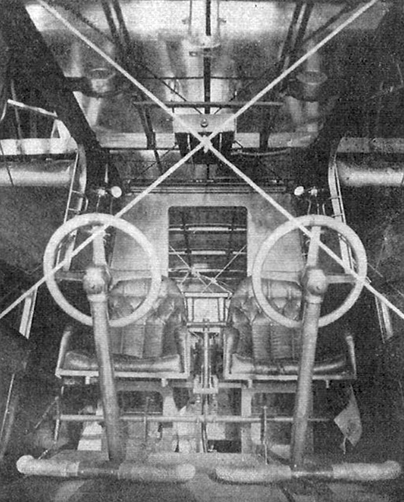


.jpg)