USSR (1938-1940) Experimental long-range bomber – One prototype
With the rapid expansion of Soviet aviation in the 1930s, radical new design concepts were constantly being developed, producing a number of eccentric designs that hoped to break the mold. Among the many different concepts, one particularly unusual design emerged in the form of a twin-fuselage, bat-winged aircraft created by Viktor Nikolayevich Belyayev.
This aircraft, known as the Belyayev DB-LK, featured two fuselages, connected by a central wing section with a glazed rear cone. Despite its unconventional layout, testing showed that the DB-LK was a stable and reliable aircraft. However, the Soviet aviation industry at the time prioritized more conventional designs for long-range bombers with the onset of war, which ultimately doomed the project before it could progress further.
Belyayev DB-LK was an unusual twin-fuselage long-range bomber prototype. Source: Reddit
History
Following the end of the First World War and the later Russian Civil War, a new nation emerged from the remnants of a once-mighty empire: the Soviet Union. During the 1920s, it began the slow process of rebuilding its shattered industry. In order to recover, the Soviet political and military leadership decided to prioritize large-scale industrial development, and enormous financial resources, manpower, and raw materials were committed to achieving this goal. As a result, new technologies were quickly introduced, leading to a period of rapid industrial expansion.
The aviation sector also benefited from this renewed focus. A series of new projects, both civilian and military, were initiated to rebuild and modernize the nation’s air capabilities. Before the First World War, in the now-lost Russian Empire, there had been considerable developments in airliner design. However, progress was halted by the outbreak of the First World War, and the devastation caused by the subsequent Civil War. By the early 1920s, the aviation industry’s infrastructure was in ruins, and many of its original engineers and experts had either fled the country or been killed.
By the 1930s, new experts were eager to test various ideas and concepts. Among them was Viktor Nikolayevich Belyayev. Born in 1896 (Moscow, Russian Empire), Belyayev showed a strong interest in aviation from an early age and was an enthusiastic engineer. During the late 1920s, he worked with Andrei Nikolayevich Tupolev’s Experimental Design Bureau, and later with Aeroflot, the Soviet civil aviation operator.
Viktor Nikolayevich Belyayev was a Soviet aircraft designer and aviation enthusiast who was particularly keen on finding ways to minimize aerodynamic drag while improving overall flight performance. Source: en.wikipedia.org
Belyayev had a particular fascination with a bat-wing, sometimes also described as a butterfly wing shape, design, featuring a slightly forward-swept wing with tips that curved gently backward. At the time, aviation worldwide was marked by the introduction of numerous experimental and innovative concepts. With such rapid technological progress, there was plenty of room for improvement and innovation, and eccentric ideas found fertile ground for development. Belyayev believed that this bat-wing configuration could significantly improve longitudinal stability while also reducing overall drag.
Like many other aircraft engineers who often lacked adequate funding, he decided to test his ideas using simple and inexpensive gliders. In 1920, he built a fully operational glider. In 1933, he managed to construct a glider designated BP-2. It used the bat-wing layout and also featured an unusual twin-tail assembly connected by an extended elevator. The glider was tested in a flight from Crimea to Moscow, towed by a Polikarpov R-5. The tests were successful, which encouraged Belyayev to continue experimenting with new fuselage designs. He was particularly interested in an unconventional twin-fuselage arrangement.
The Belyayev BP-2 was used to test some of his concepts. It successfully flew from Crimea to Moscow while being towed in 1933. Source: airwar.ru
The Development of a New Project
Following his research and experimentation with glider design, Belyayev eventually felt that he had gathered enough knowledge and design experience to put his ideas into practice. In 1934, he began working on a new twin-fuselage, 10-seat transport aircraft. Each fuselage was fitted with a 750-hp engine.
In addition to developing new wing designs, Belyayev also theorized methods to significantly reduce aircraft drag. Conventional twin-engine aircraft had their engines mounted on the wings, which inevitably created drag that could not be eliminated. Belyayev’s new concept was to extend the engine nacelles and use them as the fuselage itself. This meant that no additional structural elements had to be attached to the wing, thereby removing unnecessary drag and creating a more aerodynamically efficient aircraft.
In the late 1930s, the Soviet Air Force issued a requirement for a new long‑range bomber. Belyayev decided to take this opportunity. He essentially reused his original civil aircraft design and adapted it for military use. In 1938, he approached the Soviet Air Force with his proposal for a new long-range bomber. This time, he received approval to construct a working prototype, which was completed rather quickly by November 1939. The resulting aircraft made use of his earlier concept: it featured two fuselages that, technically speaking, functioned more like elongated engine nacelles.
The aircraft received a simple designation: DB-LK. While not entirely clear, this was most likely an abbreviation of Dalniy Bombardirovshchik – Letayushcheye Krylo, meaning Long-Range Bomber — Flying Wing. It is also often referred to by its designer’s name as the Belyayev DB-LK. During the testing phase, it also carried the nickname Kuritsa (Eng. Chicken), given by the test pilot who was afraid to fly it.
Experimental Flights
Once the DB-LK prototype was completed, it was cleared for its first flight tests. While Belyayev may have had doubts about the realization of the entire project, he likely never expected that, despite the vast size of the Soviet Union, not a single test pilot was willing to fly his plane. At this time, most pilots were still flying older biplane designs, and many were often reluctant to test newer aircraft. For example, some even hesitated to fly low-wing monoplanes, which were still unfamiliar to many aviators. This hesitation stemmed both from a general fear of experimental aircraft and, to an even greater degree, from an ingrained belief that proven older designs were superior to new, untested ones. In any case, Belyayev unexpectedly found himself unable to secure a willing test pilot.
This situation dragged on until 1940. That year, the Soviet Directorate of the Air Scientific Test Institute issued an official order assigning pilot M. A. Nyukhtikov to test the aircraft. There was little point in keeping a fully functional machine sitting idle on the ground. To support the pilot during the trials, lead engineer T. T. Samarin and test observer N. I. Shaurov were also assigned to the project.
After several initial flights, Nyukhtikov reported that the aircraft’s controls were heavy and difficult to operate. In addition, he noted that the landing gear should be strengthened. A commission of the Scientific Test Institute, led by A. I. Filin agreed that the control system needed refinement but rejected the pilot’s concerns regarding the landing gear. This decision proved premature, as only a few days later, during a flight test involving Filin himself, one of the landing gear legs collapsed.
Despite test pilots repeatedly pointing out that the landing gear was too fragile, it ultimately took an accident for their superiors to finally realize that this was something that needed fixing and improvement. Source: militarymatters.online
Sudden End of the Project
After a series of test flights, the DB-LK, despite its unconventional, inverted-gull twin-fuselage design, proved to be an airworthy and well functioning aircraft. During testing, the DB-LK could easily reach speeds of up to 488 km/h (303 mph) at an altitude of 5 km (16,400 ft). When fully loaded, it was also capable of climbing to around 8.5 km (28,000 ft). In total, more than 100 test flights were conducted without any major incidents, demonstrating that the overall design was sound.
Complaints from the test pilots focused on the limited visibility experienced by both the pilot and the navigator. Despite this, the DB-LK was viewed as an aircraft with significant potential for future service within the Soviet Air Force.
Then, suddenly, the project was shut down. This occurred for several reasons, though not necessarily because of flaws in the design. By late 1940, war was raging in Western Europe between Germany and Britain, and a wider conflict seemed increasingly possible. The Soviet leadership did not want to take risks with an aircraft considered highly unorthodox. The DB-LK’s twin-fuselage layout likely contributed to these concerns. Instead, the authorities decided to focus production efforts on the more conventional and already-established IL-4 bomber. With that decision, all work on the DB-LK stopped. Its final fate is unclear, but it was likely scrapped.
Technical characteristics
The DB-LK featured an unconventional overall layout, lacking a traditional central fuselage. Instead, the crew stations, armament, and most of the onboard equipment were housed inside two elongated engine nacelles that terminated in glazed tail cones (gondolas), somewhat reminiscent to the aft section of the later German Fw 189. In practical terms, these extended nacelles functioned as the aircraft’s fuselage. Each semi-monocoque structure was built from a framework of metal frames and longerons, covered with duralumin skin. The two glazed cones could be mechanically rotated 360°, boosted by small electric motors mounted on top of the fuselages. This was designed to provide the best possible angle for the rear gunners, while retaining aerodynamic shape.
The DB-LK’s wings featured a distinctive layout. In addition to the characteristic “batwings,” the aircraft incorporated a central wing section positioned between the two fuselages. The wings were slightly forward-swept and ended in backward-curved tips. Structurally, they consisted of a light metal stressed-skin construction over a conventional airframe. The outer wing panels used a Göttingen 387 airfoil profile, while the center section employed a CAHI (TsAGI) MV-6bis profile. The wing leading edges were curved at an angle of –5° 42′.
The aircraft’s rather unusual wings were slightly forward-swept and finished with backward-curved tips. Structurally, they featured a light metal stressed-skin construction built over a conventional airframe. Also note the glazed rear fuselage cone section, where the rear gunner would have been positioned. Source: forum.warthunder.com
The rear tail assembly was mounted on the central wing section between the two fuselages. It consisted of a single vertical fin with a large rudder. Above the rudder, a small horizontal stabilizer was installed, fitted with two large elevators, one on each side.
The rear tail section was also unusual, being positioned in the middle of the central wing section and featuring a large rudder with a small tailplane. Source: wikipedia.org
The landing gear retracted rearward, with one wheel (900 × 300 mm) housed in each fuselage section. During later testing, this arrangement was redesigned, and the gear was modified to retract forward instead. The entire landing gear system was hydraulically operated. A small fixed tailwheel (450 × 150 mm) was installed at the bottom of the tail unit.
The DB-LK was powered by two Tumansky M-87B 14-cylinder radial engines, each delivering 950 hp. These drove three-bladed variable-pitch propellers. It was planned to replace them with the more powerful 1,100 hp M-88 engines, or even the 1,700 hp M-71, but these upgrades were never implemented as the project was ultimately cancelled. Fuel was stored in both the wing and fuselage tanks, with a total capacity of 3,444 liters (910 US gallons)..
Behind each of the two engines, a cockpit with a rear-sliding canopy was installed. The DB-LK was designed to be operated by a crew of four: the pilot, navigator, and two rear gunners. The pilot occupied the left cockpit, and the navigator the right. The gunners were positioned in the two rear glazed cones, with one of them also serving as a radio operator. Crew members entered their positions through the roof hatch doors.
Given its role as a long‑range bomber, Belyayev intended for the aircraft to have a fairly respectable defensive armament for its day, consisting of six machine guns. Both rear glazed tail cones were fitted with mounts for twin 7.62 mm (.30 in) ShKAS machine guns. These weapons had a firing arc of –10° to +10° in all directions. However, the gunner could rotate the glazed cones themselves, allowing him to reposition the guns and further increase the weapon’s effective defensive arc.
The interior of one of the two fuselages. On the right, the rear machine-gun mount is visible, while on the left side, you can see the radio equipment and the mechanism used to rotate the entire glazed tail cone. Source: forum.warthunder.com
In addition to these four rear-mounted machine guns, two more were installed in the leading edge of the center section and operated by the pilot. Altogether, approximately 4,500 rounds of ammunition were carried for all six weapons.
For attacking ground targets, bombs were to be employed. The bomb bays were located behind the landing‑gear doors in each of the nacelles. Each of the two bomb bays could carry up to 1 tonne (2,200 lb) of bombs, or alternatively four 250 kg (550 lb) or two 500 kg (1,100 lb) bombs per bay, four in total. In addition, a container with 59 smaller bombs could have been used instead. Lastly, an additional external bomb rack capable of carrying up to one tonne could be attached to the central wing section.
Cocnlusion
The Belyayev DB-LK is one example where the overall visual design essentially killed the project. The aircraft itself had no unresolvable flaws. In fact, it demonstrated generally good flight performance. It carried a large bomb payload, and its defensive armament, while not covering every angle, was still respectable. Most importantly, it did not suffer any major problems during the initial test flight phase.
Its main downside was its unusual overall appearance, which may have caused significant concern among industry decision-makers when it came time to consider a production order. It can be assumed that this was one of the key reasons it was cancelled, along with its prototyping being interrupted by the start of the Second World War. Soviet authorities preferred more conventional, proven designs and did not want to commit to a highly unorthodox aircraft that had no equivalent or prior service experience anywhere in the world.
Belyayev DB-LK specifications
Wingspan
21.6 m / 70 ft 10 in
Length
9.8 m / 32 ft 1 in
Wing Area
56.9 m² / 612 ft²
Engine
2x Tumanskii M-87B 950 hp 14 cylinder radial engines
Poland (1934-1939) Type: Light Bomber/Reconnaissance, Number built: 240
In the early 1930s, the Polish Air Force began modernizing its fleet as tensions rose in central Europe. Among its top priorities was acquiring a specialized class of aircraft capable of performing both reconnaissance and bombing missions. The goal was to develop a modern, all-metal aircraft that could fulfill both vital combat roles. This ambition materialized in the form of the PZL.23, produced in two main variants: the PZL.23A, and the improved PZL.23B. A total of 250 aircraft were built, and the design even achieved modest export success. These aircraft went on to serve in the early stages of the Second World War II, seeing combat against both Germany and the Soviet Union, with some measure of success.
The Polish Bomber/reconnaissance plane PZL.23 Source: https://en.wikipedia.org/wiki/PZL.23_Kara%C5%9B
History
At the start of the 1930s, the Polish Air Force was primarily equipped with outdated aircraft. This was the case with its bomber formations, which mostly relied on French canvas-skinned, biplane bombers, such as the Breguet 19. These aircraft were fragile, had a relatively small bomb-carrying capacity, and were intended more to harass the enemy than to inflict significant damage.
The role of the light bomber/reconnaissance aircraft was mostly taken by the French Breguet 19 biplane in the post war years. Source: https://commons.wikimedia.org/wiki/File:Samolot_Breguet_19_B2_NAC_1-W-1555-2.jpg
In 1931, the Polish Air Force initiated the development of a new bomber designed to provide close support to ground forces. In addition, it was also to perform the role of reconnaissance operations, this request being primarily based on the experience gained during the Russo-Polish War of 1919–1920. During that conflict, both sides employed a limited number of aircraft, mainly for reconnaissance and bombing operations. As a result, the Polish Air Force sought to replace its aging fleet with new aircraft capable of effectively performing both roles.
In 1931, the Polish Air Force issued a requirement for a new single-engine, monoplane aircraft. It was to accommodate three crew members and be capable of carrying several hundred kilograms of bombs, serving the dual roles of bomber and reconnaissance platform. Few proposals were submitted, including the high-wing PSW.19 and the Lublin R.XVII biplane. Of the two, only the PWS.19 was built and tested, but it was ultimately not accepted for service.
The PSW.19 was a proposal from Podlaska Wytwórnia Samolotów (Eng. Podlachian Aircraft Factory) for a new bomber/reconnaissance plane. However, the design was not accepted for service. Source: https://www.armedconflicts.com/PWS-19-t185849#valka_group-2
The winning design came from a young engineer named Stanisław Prauss, working at Państwowe Zakłady Lotnicze (PZL, or State Aviation Works). Prior to this project, Prauss had worked on the PZL.13, a single-engine passenger aircraft, which was a modern design for its time, featuring an all-metal structure. Despite its innovative features, the project was ultimately canceled in 1931.
Following that setback, Prauss and his team dedicated much of late 1931 to drafting design plans, and performing critical calculations for the new military aircraft. In order to accelerate development, Prauss chose to incorporate several elements from his earlier PZL.13 project into the new design.
To expedite development, Prauss decided to incorporate several elements from his earlier PZL.13 project. The overall shape of his earlier design was clearly reflected in the later production aircraft, including the fixed landing gear, engine configuration, and fuselage design. Source: http://www.samolotypolskie.pl/samoloty/2296/84/PZL-13
By early 1932, a full-scale wooden mock-up of the fuselage was completed. Both the drawings and the mock-up were presented to the Polish Aviation Department in the spring of that year. After analyzing the wooden construction and technical documentation, the department approved the project and ordered the construction of three prototypes for testing.The first prototype was completed by 1934, powered by a 593 hp Bristol Pegasus II M2 radial engine. Although not of Polish origin, the engine was produced under license in Poland, with the original rights obtained from the United Kingdom. The overall design was simple: a conventional linear crew arrangement with a weapons bay between them. The rear gunner was also expected to serve as the bombardier, for which a small under-fuselage compartment was provided. For defense, the rear gunner operated two machine guns, one mounted dorsally and the other ventrally. Lastly, another crew member was tasked with aiming and releasing the bombs. A forward-firing machine gun was also planned for the pilot’s use, though it remains unclear whether this was ever actually fitted to the prototype.
The prototype, designated PZL.23/I, was flight-tested in early April 1934. Interestingly, it received the nickname Karaś, meaning Crucian-carp, a species of fish. Its performance in the was rather poor, and several design flaws became apparent, such as a cramped interior, limited crew visibility, and vibrations in the rear section. Bombing trials were also problematic: when released, the bombs would shift from a vertical to a horizontal position, then back to vertical, as they fell from the aircraft. This erratic behavior significantly reduced bombing accuracy.
Further tests were carried out to refine the overall design throughout 1934 and into 1935. Eventually, the prototype was handed over to the Polish engineering college, where it was used for training new engineers. It remained there until the fall of Warsaw in September 1939.
The first prototype, although successfully flight-tested, was found to have several design flaws. As a result, after 1934, it was eventually repurposed as an instructional airframe.Source: https://jmodels.net/de-hombres-y-maquinas/aire-air/pzl-23-karas/
In late 1934, work began on a second prototype, designated PZL.23/II. The most notable change was the removal of the centrally located bomb bay. Instead, bombs were mounted under the wings, and the former bomb bay space was expanded to provide more space and improve visibility for the crew. Additionally, the engine was lowered by 10 cm to improve the pilot’s forward view. Other improvements included the addition of new leading-edge slats and flaps.
Testing revealed that many of the previously identified issues had been resolved; however, forward visibility was still considered unsatisfactory. Unfortunately, testing of the PZL.23/II came to a sudden and tragic end. At the end of July 1935, all three crew members were killed in a crash landing. The investigation concluded that the pilot had made a serious error, with some speculating it may have been a deliberate act of suicide.
Following the loss of the previous aircraft, another prototype (designated PZL.23/III) was constructed in 1935. This version incorporated several improvements over its predecessor, including an enlarged canopy and a raised pilot’s seat. These modifications significantly enhanced the pilot’s forward visibility, addressing a major flaw in earlier designs.
An especially interesting feature of the PZL.23/III was the addition of a hydraulically operated rear machine gun mount. This system allowed the rear gunner, if necessary, to engage targets approaching from the front by raising the machine gun above the forward fuselage. However, while seemingly innovative, this setup was likely difficult to use effectively in combat.
Production and Service Problems
Following the successful testing of the third prototype, the Polish Air Force placed an order at the end of 1935 for the production of 200 aircraft. These were to be manufactured at the PZL factory in Warsaw-Okęcie, with the first batch of 40 aircraft scheduled to begin production at the start of 1936. However, after only a few units were built, production was abruptly halted due to a critical issue: the unreliability of the Bristol Pegasus engines.
These engines, produced under license in Poland, were plagued by numerous mechanical problems that required extensive troubleshooting and rework. To make matters worse, the engines were not manufactured in the UK, which meant acquiring replacements or parts from abroad was not an option, given differences in manufacturing tolerances. It wasn’t until September 1936 that these issues were finally resolved, allowing production to resume. The aircraft entered service under the designation PZL.23A, and the initial order of 40 aircraft was finally completed in November 1937.
Unfortunately, matters only worsened once the aircraft entered operational service. The planes delivered to the Polish Air Force proved deeply disappointing, bordering on unusable. The engines were underpowered, limiting the aircraft to a maximum altitude of just 3,000 m. Additionally, the automatic leading edge slats frequently malfunctioned, often deploying mid-flight without warning and causing severe stability problems. As a result, the aircraft was ultimately deemed unsuitable for combat roles and relegated primarily to reconnaissance duties.
Need For Improvements
Abandoning the PZL.23 at that point would have seemed a waste of both resources and time, two things the Polish military could ill afford. Starting from scratch would have required significant time, with no guarantee that a new design would be any more successful. In the face of rising threats from both Germany and the Soviet Union, officials in the Polish Air Force sought ways to salvage the PZL.23 project.
One of the first PZL.23A production aircraft. Source: https://tvd.im/aviation/1666-pzl-p-23-karas.html
The first option considered was installing a stronger engine. PZL engineers decided to equip the aircraft with the newly produced Bristol Pegasus VIII engine, which had just entered production in Poland. This engine offered the advantages of its greater performance and a reliable local supply of parts, making it a logical choice. A prototype designated PZL.23/III was fitted with this engine and tested.
The third prototype was equipped with the new engine. Source: T. J. Kopanski PZL.23 Karaś
Although the speed increased only slightly (from 263 km/h to 274 km/h), the upgraded aircraft could now reach an altitude of 7.3 km, a significant improvement over the previous 3 km ceiling. In addition to the new engine, several other modifications were introduced: the leading-edge slats were removed, the elevator was redesigned, and an extended antenna mount was added to the observer’s gondola for in-flight radio use.
Lastly, the new variant received two machine gun mounts in the forward engine compartment, compared to only one in the earlier model. However, due to a shortage of available machine guns, only one was actually installed in most aircraft. With these improvements, production of the updated model continued under the designation PZL.23B (sometimes referred to as Karaś II). With the introduction of the B variant, the remaining A variant aircraft were mainly employed as trainers. Some of them were thus equipped with dual controls.
The most common variant was the PZL.23B, which resolved many issues with the previous model. Source: https://www-airwar-ru.translate.goog/enc/bww2/pzl23.html?_x_tr_sch=http&_x_tr_sl=ru&_x_tr_tl=en&_x_tr_hl=enNearly all PZL.23A aircraft were converted into trainers by rebuilding them with dual controls, as was likely the case with this example, which probably belonged to the training school at Krosno. Source: https://www-airwar-ru.translate.goog/enc/bww2/pzl23.html?_x_tr_sch=http&_x_tr_sl=ru&_x_tr_tl=en&_x_tr_hl=en
Production
After the production of 40 PZL.23A aircraft, the remaining 160 units were built exclusively in the upgraded PZL.23B variant, and the initial order for 200 aircraft was completed by September 1937. Due to high demand, the Polish Air Force secured additional funding and requested the construction of 50 more aircraft. This follow-up order was fulfilled by February 1939.
In total, 240 aircraft of the Variant A and B (in addition to three prototypes) would be built.Source: https://panssarivaunut.blogspot.com/2016/02/pzl23-karas.html
Experimental Project
Dive Bomber
While the PZL.23 shared some visual similarities with the German Ju 87 dive bomber, the Polish Air Force initially did not consider employing it in this role. However, by 1936, the idea of using the aircraft as a dive bomber began circulating among Air Force officials. To test the feasibility of this concept, one PZL.23A was modified to serve as a prototype, designated PZL.23/IV. This prototype could be easily identified by the removal of the bombardier’s gondola.
The proposed armament included two forward-firing and two rear-mounted machine guns. The estimated bomb load was 300 kg, though it was hoped that this could be increased to 800 kg for potential export customers. Testing was carried out by the Air Force Technical Institute (ITL) in August 1936. Despite the modifications, it’s overall performance did not improve significantly, and the aircraft proved unsatisfactory in dive-bombing operations.
PZL.42
In April 1937, the prototype was further modified by replacing the single vertical stabilizer with twin vertical tails. This change aimed to improve the gunner’s field of fire. Bombing trials conducted with this version were somewhat more promising. However, for unclear reasons, the aircraft remained at the prototype stage, with only one example ever built. It was later used as a training aircraft until it was destroyed in a bombing raid in September 1939.
The PZL.42 prototype was tested with the new tail design. Source: https://jmodels.net/de-hombres-y-maquinas/aire-air/pzl-23-karas/An aircraft lost in one of many German bombing runs during September 1939. Source: T. J. Kopanski PZL.23 Karaś
In Service
As the first PZL.23A aircraft became available, they were issued to units for familiarization. The first units to be equipped, in September 1936, included the 11th and 12th Flights of the 1st Air Regiment. The 21st Flight of the 2nd Regiment also received some of these aircraft. However, due to the poor performance of the PZL.23A, they were soon relegated to training duties.
With the introduction of the improved PZL.23B variant in early 1937, more than a dozen units received the updated aircraft. The Polish pilots experienced some difficulty adapting to the new type. This was not due to any inherent flaw in the aircraft or deficiencies in training, but rather because most pilots had been accustomed to flying older biplanes. This issue was not unique to Polish pilots—air forces across Europe faced similar challenges during this period of transition to more modern monoplanes.
Nonetheless, the aircraft was involved in numerous accidents. Between early 1937 and August 1939, a total of 23 aircraft were involved in various incidents, resulting in the tragic loss of 55 lives.
The PZL.23 would be dispatched in small groups of up to 10 aircraft to various units of the Polish Air Force. Source: https://en.wikipedia.org/wiki/PZL.23_Kara%C5%9B
In Action
Border Actions
The PZL.23 saw its first operational use against Poland’s neighbors in the year 1938, a particularly turbulent moment in this part of Europe. Nearly all the nations in central Europe had once formed much of the German and Austro-Hungarian Empires (including Poland), were embroiled in long-standing border disputes. These tensions escalated rapidly following 1938 as political pressure continued to mount across the continent.
Poland, eager to assert control over territories it considered historically its own, sought to occupy several neighboring provinces. In March 1938, a border clash between Poland and Lithuania triggered considerable alarm, prompting the partial mobilization of the Polish Air Force. However, the operation was poorly organized, hastily executed, and ultimately too late to have any significant impact.
To make matters worse, the relocation of several PZL.23 aircraft to an unprepared airfield near Wilno led to the crash-landing of three planes. By the 20th March, the brief conflict had subsided. Nonetheless, in an effort to intimidate Lithuania, the Polish military carried out a large-scale demonstration flight of over 100 PZL.23 bombers near the Lithuanian border.
The PZL.23 was deployed again in September 1938, this time against Czechoslovakia. At that point, part of Czechoslovakia had already been occupied by Germany with the approval of the Western Allies. Seeing an opportunity, Poland moved to occupy the Zaolzie region. Once again, the PZL.23 aircraft were used primarily as a show of force and did not engage in actual combat.
However, this show of force came at a significant cost. The frequent deployments accelerated the wear and tear on the PZL.23 fleet. Limited availability of spare parts meant that many planes had to be withdrawn from service due to being worn out beyond repair. As a result, some units were disbanded, while others had only a handful of operational aircraft of this type remaining.
Downfall of Poland
By July 1939, tensions between Germany and Poland had reached a boiling point, and the possibility of war between the two nations was becoming increasingly likely. In response, the Polish Air Force conducted several reconnaissance flights along the German border, primarily using PZL.23 aircraft.
On the 23rd of August, the Polish Air Force began mobilizing. According to Poland’s war contingency plan, in the event of conflict with Germany, the air force was to be divided into two main groups. One group would be placed under the direct control of the Polish High Command, while the other would be attached to various ground formations. By the end of August, nearly all PZL.23-equipped units had been mobilized and prepared for potential combat operations.
On the 31st of August, the Polish Air Force issued orders to implement the pre-war organizational distribution plan. The group under the High Command’s direct control consisted of five fighter flights and the Bomber Brigade. The Bomber Brigade included five flights of PZL.23 aircraft, which were at that point renamed Light Bomber Flights. These were supported by seven reconnaissance flights, each equipped with an average of eight PZL.23 aircraft.
The aircraft allocated to direct ground support roles for the army were dispersed in small groups across various units. Although in theory, they were meant to cover vast territories and participate in reconnaissance or bombing raids, in practice, this deployment strategy significantly reduced their effectiveness. Their numbers were too few in each location to have any real impact in combat.
As of 1st September 1939, the Polish Air Force could field only 114 PZL.23 aircraft. Of these, 50 were allocated to the Bomber Brigade and 64 were assigned to various ground forces. An additional 10 were held in reserve. At least 55 more aircraft were in storage awaiting repairs, and another 45 PZL.23s were being used as training aircraft. Some of these would be pressed into combat as a replacement when nothing else was available. The small number of available aircraft meant that the PZL.23 was a generally rare sight during the war in Poland.
Despite many misconceptions about the war, the belief that the Polish Air Force was destroyed on the first day, is simply not true. While many aircraft were indeed destroyed on the ground, many survived and saw continued use through the conflict. The PZL.23, in particular, saw considerable action in both reconnaissance and bombing roles.
The PZL.23s of the 21st Bomber Flight first entered combat on 2nd September. A single aircraft was tasked with locating a German column near Lubliniec. It successfully identified a German motorized unit and carried out an attack against it. Another aircraft was shot down while on a similar reconnaissance mission, having been engaged by four Bf 109 fighters. On September 3rd, the unit suffered further losses, with several planes downed by superior German fighters and anti-aircraft fire. By 11th September, the unit handed over its remaining four aircraft to the VI Bomber Squadron, and the surviving pilots and crew were evacuated to Romania. Between September 1st and 11th, the 21st Bomber Flight dropped approximately 10 tonnes of bombs and lost six aircraft.
The 22nd Bomber Flight saw its first action on September 3rd, attacking a German column. The bombers were engaged by enemy fighters and anti-aircraft fire, resulting in the loss of three aircraft. Two more were lost in a follow-up attack later that same day. Over the following days, the unit continued to carry out bombing raids against German forces. By 10th September, the 22nd had transferred its remaining aircraft to the VI Bomber Squadron and evacuated its personnel to Romania. By that time, the unit had dropped around 12 tonnes of bombs and lost a total of five aircraft.
A PZL.23B from the 22nd Bomber Flight, easily identified by the painted emblem of a flying dragon holding a bomb on the fuselage sides. Source: https://tvd.im/aviation/1666-pzl-p-23-karas.html
The 55th Independent Bomber Flight was another unit that saw heavy action in both bombing and reconnaissance missions. It was almost completely wiped out on 11th September, losing nine of its aircraft. Despite the losses, the unit managed to drop 14 tonnes of bombs in 40 combat sorties. The 64th Light Bomber Flight also suffered significant losses during the war, losing 21 aircraft to German fighters and anti-aircraft fire.
The 24th Reconnaissance Flight was engaged from the very beginning of the conflict, tasked with spotting enemy formations and tracking their movements. On the 3rd September, six of its aircraft took part in a bombing run against a German armored column near Rabka. Polish pilots reported scoring several hits on enemy targets, although one aircraft was lost to anti-aircraft fire.
Despite sustaining losses, the unit still had operational aircraft by the 14th September. The following day, one aircraft was assigned the dangerous task of delivering a message to the Polish High Command in besieged Warsaw. The pilot had to fly 360 km over enemy-held territory and land in a city under siege, with no guarantee that the airfield was still secure. Against the odds, the mission was successful. The aircraft even managed to take off again and return, despite German attempts to shoot it down. The unit remained active until 17th September, when it was forced to evacuate to Romania due to the Soviet invasion from the east.
The 41st Reconnaissance Flight operated a small number of improved PZL.43A aircraft (an export version of the PZL.43 that had been sold to Bulgaria). While most of these aircraft were delivered to Bulgaria before the outbreak of war, a few remained in Poland awaiting final delivery. Initially, they could not be used due to missing components.
Interestingly, on the 6th September, an element of this unit engaged a German reconnaissance balloon near Przasnysz. Despite being protected by anti-aircraft guns, the Polish aircraft managed to shoot it down. By the 10th September, the unit had only two PZL.43As remaining. On that day, during a reconnaissance mission, one of the aircraft was hit by anti-aircraft fire and crashed, killing its crew. The following day, the last remaining aircraft was damaged by an enemy fighter and subsequently lost in a crash landing.
A PZL.23B from the 41st Reconnaissance Flight. Source: https://www-airwar-ru.translate.goog/enc/bww2/pzl23.html?_x_tr_sch=http&_x_tr_sl=ru&_x_tr_tl=en&_x_tr_hl=en
By the time of Poland’s surrender on the 6th October, 1939, the PZL.23 aircraft of the Bomber Brigade had conducted over 186 sorties, during which they dropped approximately 64 tonnes of bombs. Meanwhile, the independent flight units assigned to the Army saw even more combat activity, flying around 260 sorties. However, these units dropped only about 20 tonnes of bombs, as their missions were primarily focused on reconnaissance rather than bombing enemy positions and forces on the move. Of the 140 aircraft deployed, over 100 were eventually lost in combat during the war. Far from the myth that the Polish Air Force was destroyed on the first day of the war, they fought with every tool at their disposal until the end.
By the end of the war in Poland, some 120 PZL 23 would be lost in combat. Source: https://www.reddit.com/r/WWIIplanes/comments/12bnmuw/german_personnel_examine_the_remains_of_a_polish/
In the Foreign Service
As soon as the first PZL.23 aircraft left production facilities, the Polish authorities were eager to generate foreign interest. In the spring of 1936, the PZL.23/III was presented at the air fair in Stockholm. Later that year, in November, another aircraft was exhibited at the Paris Air Show. Despite these efforts, Poland failed to attract any significant foreign interest in the design.
One PZL.23B was modified with a more powerful 925 hp Pegasus engine and equipped with a three-bladed, variable-pitch propeller. This variant was intended for export, but it failed to generate any interest, and was eventually reverted to the standard PZL.23B configuration.
The PZL.23B was modified with a 925 hp Pegasus engine, equipped with a three-bladed, variable-pitch propeller. Source; T. J. Kopanski PZL.23 Karaś
Bulgaria
The PZL.23 would see some export success. In March 1936, a delegation was sent to Poland by Bulgaria to evaluate and potentially acquire aircraft for their own use. Following a series of negotiations, Poland agreed to sell them 12 PZL.23 bombers.
However, the Bulgarians requested that the aircraft be powered by Gnome-Rhône engines, which presented a design challenge. The positioning of the Gnome-Rhône radial engines and their cylinders prevented the installation of the forward-firing machine gun originally housed within the engine compartment. Polish engineers had to overcome this by finding a new, suitable position for the machine gun within the fuselage, an issue that took some time to resolve.
By the end of summer 1936, the modified variant was ready. Due to changes in both the engine and fuselage design, the new aircraft was given a different designation: PZL.43. Although the contract between Poland and Bulgaria was signed on the 9th April 1936, actual production faced delays. The main issue was the engine: the requested Gnome-Rhône 14N had to be imported from France.
Bulgaria was the only country that showed interest in this aircraft, acquiring around 50 of a modified variant designated as PZL.43. Source: https://jmodels.net/de-hombres-y-maquinas/aire-air/pzl-23-karas/
It was not until May 1937 that the last of the ordered aircraft arrived in Bulgaria. The Bulgarians were satisfied with its performance and placed a new order for 42 additional aircraft. These were to be powered by the Gnome-Rhône 14N engine and received the new designation PZL.43A. Most of these aircraft were delivered by late August 1939.
Following the German occupation of Poland, the few PZL.43A units that had not yet been delivered were briefly tested by the Germans before being sent on to Bulgaria. In total, Bulgaria acquired 50 aircraft, comprising both the original PZL.43 and the updated PZL.43A variant.
During the war, these aircraft were primarily used for training purposes, though they were occasionally employed in operations against Yugoslav partisans. By September 1944, due to a lack of spare parts, most had been withdrawn from service. A few remained operational until 1946, when they too were finally scrapped.
Romania
Besides Bulgaria, Romania also operated some of these aircraft. They came into Romanian possession following the defeat of Poland in September 1939, when a group of 21 aircraft managed to escape German forces by fleeing to Romania. Of these, the Romanians were able to restore 19 to operational status, using the remaining two for spare parts. The aircraft saw extensive action against the Soviets, serving both in bombing, and reconnaissance roles, until 1943, after which they were reassigned to secondary duties. The last of these aircraft remained in service until 1946, when it was finally scrapped.
Romania operated at least 19 fully operational aircraft until 1943 when they were relocated for second line duties. Source: https://ww2aircraft.net/forum/media/a-crashed-pzl-23-karas-no-12-romanian-af.25926/
Germany
After their victory in Poland, the Germans managed to capture several PZL.23 aircraft, most of which were either in poor condition or heavily damaged. They repaired a few PZL.43s and used them for testing purposes. Beyond that, however, they showed little interest in these aircraft.
Germans tested some captured aircraft but showed little interest in them. Source: T. J. Kopanski PZL.23 Karaś
Soviet Union
The Soviets also managed to capture several PZL.23 aircraft, some of which were actually in working condition. These appear to have been put to some use by the Soviets; however, beyond that, nothing else is known about their ultimate fate.
Technical characteristics
The PZL.23 was a single-engine, low-wing aircraft intended for both bombing and reconnaissance missions. The fuselage featured an oval-shaped fuselage cross-section built using a framework of stringers and struts. The tail section employed a semi-monocoque construction for added strength and reduced weight. The entire fuselage was then skinned with duralumin sheeting.
An excellent illustration of the PZL.23 internal component and crew’s positions. Source: https://panssarivaunut.blogspot.com/2016/02/pzl23-karas.html
The wings were constructed in three main sections. The first section consisted of two spars that formed an integral part of the structure. In addition to serving as the attachment point for the rest of the wing structure to the fuselage, this central section also housed the mounting points for the two landing gear units. It was further reinforced to support a bomb rack installed beneath the aircraft fuselage.
Following this were the two outer wing sections, which were built using an innovative method. These outer parts featured a torsion box design, constructed with corrugated heavy-gauge duralumin sheets. These were connected spanwise by additional corrugated, stress-bearing duralumin plates with a smooth finish. Finally, the wing tipsand trailing edge slats were attached to complete the wing. The tail assembly was built using spars and ribs, all of which were covered in duralumin for structural strength and aerodynamic efficiency.
The wing was made up of three sections. The first section was directly attached to the fuselage and housed the landing gear and fuel tanks. This central section was flanked by the two remaining outer wing panels. Source: https://www-airwar-ru.translate.goog/enc/bww2/pzl23.html?_x_tr_sch=http&_x_tr_sl=ru&_x_tr_tl=en&_x_tr_hl=en
The cockpit was positioned at the front of the aircraft. In its early development phase, the PZL.23 suffered from poor forward visibility. This issue was eventually addressed in the B variant by lowering the engine and raising the pilot’s seat. Directly behind the pilot sat the observer and bombardier, who was provided with a glazed canopy offering fairly good all-around visibility. Beneath the fuselage was the bombardier’s gondola. Finally, at the rear of the aircraft was the gunner’s position
Close-up view of the aircraft glazed crew compartment. Source: https://panssarivaunut.blogspot.com/2016/02/pzl23-karas.htmlThe instrument panel. Source: https://jmodels.net/de-hombres-y-maquinas/aire-air/pzl-23-karas/At the bottom of the fuselage, a small bombardier’s gondola was installed. Source: J. B.Cynk The P.Z.L.23 Karaś
The first variant was powered by a 670 hp Bristol Pegasus II M2 engine. Later production aircraft were equipped with the more powerful 710 hp Bristol Pegasus VIII. In both versions, a two-bladed fixed-pitch propeller was used.
The fuel load consisted of 740 liters stored in six fuel tanks located within the central section of the wings.
The landing gear comprised two front-mounted fixed wheels (775×240 mm), each enclosed in aerodynamic spats. On many training aircraft, these spats were removed. To absorb shock during landings, shock absorbers were mounted on the landing gear legs. At the rear, a small tail skid with a shock absorber was installed.
The defensive armament included one forward-mounted 7.92 mm Wz.33 (Karabin lotniczy wz. 37) machine gun. The rear was protected by two 7.92 mm Wz.36 machine guns. Each machine gun was supplied with 600 rounds of ammunition. The B variant was designed to accommodate two forward-firing guns, but due to a lack of mounts, only one was typically installed. A ventrally mounted machine gun was also present, with an elevation and traverse range of 60 degrees.
For self-defense from rearward attacks, two machine guns were installed. Source: T. J. Kopanski PZL.23 Karaś
Initially, the aircraft’s bomb bay was located just behind the cockpit. However, during early testing, this design proved to be inefficient and was soon eliminated. Instead, bombs were mounted on an external rack positioned under the central fuselage.
This bomb rack could carry a payload ranging from 300 to 700 kilograms, typically using one of the following configurations: six 100 kg bombs, eight 50 kg bombs, or twenty-four small 12.5 kg bombs. In practice, however, loads exceeding 400 kg were rarely employed.
Production and Proposed Versions
PZL.23 I-III Prototypes – A small series of three prototypes
PZL.23A – An experimental version created by combining the Re.2002’s fuselage with the Re.2005’s wings. One built but never used operationally.
PZL.23B – possibly one modified for this role.
PZL.43 – Variant developed for Bulgaria
PZL.43A – Further improvement over the previous variant
PZL.23/IV – Proposed dive-bomber variant remained at prototype stage
PZL.42 – Future modification with new tail assembly, used as training aircraft until destroyed in September 1939,.
Operators
Poland – Operated fewer than 50 aircraft.
Bulgaria – Purchased 50 PZL.43 and PZL.43A aircraft, with a few remaining in service until 1946.
Romania – Acquired 21 aircraft from Polish pilots who escaped to Romania. Of these, 19 were put into service and used against the Soviet Union until 1943.
Germany – Captured numerous PZL.23 aircraft, though most were in poor condition. The Luftwaffe showed little interest in utilizing them.
Soviet Union – Also captured several PZL.23s, but there is no known record of their operational use.
Conclusion
The PZL.23 has developed something of an unfair reputation as a poorly designed aircraft. While it was far from perfect, it was not as ineffective as it is often portrayed. The aircraft did manage to inflict some losses on German forces, conduct many reconnaissance missions, and remained in service with Poland until almost the end of the campaign. However, like many of its contemporaries, it was too slow to effectively evade or counter enemy fighters. While capable in its designed role, it was adapted for various missions, some of which it was neither designed for nor particularly suited to, such as dive bombing, and it often flew missions without fighter escort. This left the aircraft highly vulnerable and with little chance of survival. Ultimately, nearly all PZL.23s were lost by the time the war in Poland came to an end.
Type: Ground anti-aircraft rocket – 83 Launchers Built
By late 1944, the Germans were losing on all fronts and the Allies were steadily advancing into Germany itself. To make matters worse, the extensive losses in manpower and equipment had become irrecoverable. As a result, various makeshift, improvised, and even obsolete weapons were brought to the front lines in a desperate attempt to halt the Allied advance. One such last-ditch effort was the creation of a 73 mm rocket launcher, intended as a close range anti-aircraft weapon by firing a volley of small rockets. While the official project name has been lost to history, it is often referred to as the 73 mm Föhn-Gerät.
Throughout history, rockets in combat were typically a cheap complement to artillery. While early rocket designs lacked the destructive power of conventional artillery, their primary role was to disrupt enemy lines and instill chaos, acting more as psychological weapons than as tools of mass destruction. By the onset of the Second World War, however, rocket technology had advanced significantly, rockets could now fire over greater ranges and deliver larger payloads, making them far more effective in both tactical and strategic contexts.
In Germany, early rocket development was largely driven by civilian efforts to explore new technologies and their potential applications. Much of this work focused on using rockets to power aircraft, exemplified by Fritz von Opel’s experimental work in the 1920s. Von Opel was assisted by another prominent aircraft designer Alexander Martin Lippisch. While technically speaking these were not real rocket-powered flights, given that these gliders did not take to the sky using purely the rocket engine but were towed to altitude. Nevertheless, these flights showed that considerable investment was going into rocketry, with the desire for it to break into new roles.
The early German rocket program was mainly intended for civilian use, such as its use in Fritz von Opel’s experimental rocket-powered glider. Soon, the Army saw a potential use of rocket technology and tried to implement it for its own use. (Source: L. Warsitz The First Jet Pilot The Story of German Test Pilot Erich Warsitz)
Over the following years, Lippisch became quite interested in rocket technology and joined the Deutsche Forschungsinstitut DFS, where he worked as an engineer. There, he developed a series of new glider designs, like the DFS 40, to test rocket propulsion. This work would eventually lead to the creation of the Me 163 rocket-powered aircraft. Another major stepping stone in rocketry was the work of Wernher von Braun. In 1932 and 1934, von Braun managed to successfully launch two rockets using liquid-fuel rocket engines. In 1935 he managed to come into contact with Dr. Ernst Heinkel 1935. With financial and infrastructure support, von Braun would participate in the creation of the first operational rocket-powered aircraft, the He 176.
The He 176 Source:luft46.com
In the early 1930s, the German military began to take an interest in using rockets to produce new artillery systems. The Germans had a unique motivation to develop rocket technology, as it was not prohibited by the terms of the Treaty of Versailles. The pioneering work of engineers like Hauptmann Dr. Ing. Walter Dornberger and von Braun played a significant role in advancing German rocket programs. Their work made it possible to create rockets that rotated around their longitudinal axis, effectively stabilizing them during flight. This innovation reduced the need for specialized wings and fins that would otherwise be required to maintain stability. As a result, a simpler, smooth-barreled launcher could be used, significantly lowering production costs while also creating lightweight launchers.
Due to its unique characteristics and capabilities, the artillery rocket held great potential as a formidable weapon. With the ability to fire over long ranges, multiple rockets could be launched rapidly from a single launcher, allowing it to carry outa rapid salvo compared to contemporary artillery pieces. Additionally, rockets could carry a larger payload than artillery shells of the same caliber, increasing their impact. However, they lacked precision and were less effective against fortified targets.
The German army formed its specialized Nebeltruppe (Eng. Smoke Troops) in 1929. These were initially equipped with large caliber mortars. As rocket launchers became available, these were then integrated in Nebeltruppen. Initially, rockets were used primarily to obscure enemy positions with smoke-generating rounds, rather than for direct attacks. Although chemical rounds were also developed, these were not employed in combat. Interestingly, they also employed rocket launchers to deliver propaganda leaflets, although they were rarely employed.
The first mass-produced rocket launcher was the 15 cm Nebelwerfer (Eng. Smoke Thrower) 41. Development of this weapon began in 1934, and it officially entered service in 1940. Designed to be simple and cost-effective, the Nebelwerfer utilized existing components to streamline development. The base of the launcher was adapted from the 3.7 cm PaK anti-tank gun carriage, and with the gun and shield removed, it was fitted instead with a six-tube launcher, each tube 15 cm in diameter. A folding pad was added to the front of the carriage for stabilization during firing.
The 15 cm Nebelwerfer 41 was one of the first, and one of the most common, rocket artillery systems. It was a towed weapon and needed a prime mover to transport it over longer distances. (Source: en.wikipedia.org)
A Literal Propaganda Weapon
Besides using rockets to deliver deadly payloads or smoke, the Germans also employed them in a rather unconventional manner: distributing propaganda leaflets over enemy lines. In 1941, they introduced the Propagandagranate 41 (Eng. propaganda grenade), a specialized 7.3 cm rocket designed for this purpose.
The Propagandagranate 41 was slightly over 3 kg in weight and about 40 cm long. It was launched from a metal frame stabilized by three fixed spades. After setting the correct firing angle, the rocket was placed into the mount and at a distance from the base of the tube. This arrangement was necessary because the rocket was ignited using a percussion-firing system, essentially functioning like a mortar.
To fire the rocket, the operator would retreat to a safe distance and pull a string to release the captive rockets. This action allowed the rocket to slide down into the base, striking a firing pin that ignited the percussion primer located at the rear.
These rockets were assigned to specialized propaganda units known as Propagandatruppen. While it is difficult to assess the exact effectiveness of this method, it was undoubtedly a unique way to distribute propaganda leaflets during the war.
The 73 mm rockets were originally designed to distribute leaflets over enemy lines (Source: www.lonesentry.com)
A New Life For The Failed Propaganda Weapon
While rockets developed during the war were primarily forms of artillery, they were not limited to this role. The flexibility of unguided rockets allowed them to be adapted for use against aerial targets and even ships. Once again, the Germans tested various such weapons when their fortunes declined, including ground-to-air missiles, intended to counter the escalating Allied bombing raids. These projects mixed results and failed to achieve the level of success their designers had hoped for. Notably, attempts to build various surface-to-air missiles were met with only limited success. As resources became scarce and the war more desperate, the Germans sought simpler, cheaper, weapon systems designed to saturate the sky with numerous rockets in the hope of bringing down enemy aircraft. One such project appears to have been initiated in 1942.
Starting such a project from scratch was not considered an option at this stage of the war. Instead, the Germans attempted to repurpose what they already had. This is where the 73 mm propaganda rocket came into play. Since the tooling for its production still existed, it was feasible to use it for creating new anti-aircraft rocket launchers. The overall design was quite simple, consisting of a box launcher, rail cages, and a control cabin, and was set on a fixed or mobile carriage.. By 1944, work on this project ran at a slow pace and not many such launchers were built.
As this was a late-war project produced under desperate conditions, not much is known about who precisely initiated it. It is known that they were developed by the Waffenprüfstelle der Luftwaffe Tarnewitz (Weapons Testing Center of the Air Force Tarnewitz). Based on several sources, it appears that the launchers were constructed by Rheinmetall. Other sources claim that Henschel built and developed it. What is certain, however, is that these weapons entered production and service in late 1944.
To provide a cost-effective means of defending vital installations, the Germans introduced the 73 mm Föhn-Gerät rocket launcher in late 1944. (Source:www.landmarkscout.com)
Production
The production of the launchers progressed at a slow pace. By 1944, only 50 units had been completed. By February 1945, this number had increased by 83, or increased to 83, though sources are somewhat unclear on the exact figure.
Designation
No official designation for this system is known to have survived. In available sources, it is often mentioned that the Germans simply referred to it as the 73 mm Föhn-Gerät. The word Föhn refers to a certain type of wind, while Gerät translates to Device.
Some internet sources also designate it as the Henschel Hs 297. Interestingly, captured systems examined by the Western Allies were designated as the 7.5 cm Multiple Fortress Rocket Launcher. This designation is incorrect in both caliber and intended purpose. For the sake of simplicity, throughout this article, we will refer to the system as the 73 mm Föhn rockets.
In Combat
A small number of these launchers were built and deployed for frontline use near the end of the war. They were primarily used to protect bridges over the German rivers on the Western Front. In particular, a few were defending the area around the Remagen bridge in 1945.
The 73 mm Raketen Sprenggranate was introduced to service near the end of the war. (Source: en.wikipedia.org)
Design
Cradle and Carriage
The 73 mm Föhn cradle features a simple conical base, above which is a saddle with two trunnions that securely hold the rocket rail box in place. The entire system could either be bolted to a concrete base, or mounted on an older 3.7 cm Flak 18, two-wheel carriage for mobility. The stationary configuration was chosen for defending critical ground targets where mobility was unnecessary. In contrast, the mobile version was likely intended for use by ground forces as a standard anti-aircraft weapon. When deployed in the field, the rocket system would be lowered to the ground, and the crew would unfold two sheet metal plates designed to provide them with a standing platform.
The 73 mm Föhn-Gerät in mobile (left) and static configuration. (Source: www.lonesentry.com)Side view of the mobile launcher variant. This version seems to be much rarer, as significantly more photographs exist of the static variant. (Source:www.armedconflicts.com)
Controls
The controls for the 73 mm Föhn system were located on the left side of the assembly and housed within a partially enclosed cabin. The front and the right side, which faced the rocket launcher, were shielded by thin sheet metal plating. This housing was not designed to protect against enemy aircraft fire but rather to guard against the exhaust generated when firing the rockets.
At the upper front of the cabin, there was a large, curved glazed window, providing the operator with a mostly field of view. The controls themselves were straightforward; elevation was adjusted using a handwheel, while traversal was managed with a simple flat metal bar, likely welded to the right-side armor of the cabin. To traverse the system, the operator would push the bar forward or backward with their left hand, pivoting the box launcher on its mount.
This greatly illustrates the position of the operator and the two control units (a bar and hand wheel) for elevation and traverse. Interestingly this weapon appears to be a prototype, as it has more launchers than those found at the frontline. (Source: www.armedconflicts.com)A rear view of the operator’s partially protected cabin. The armor was too light to provide effective protection against enemy return fire; instead, its primary purpose was to shield the operator from the rocket’s exhaust. (Source: www.armedconflicts.com)
Armament
The project was based on the 73 mm propaganda rocket but required several modifications. The rocket’s steel body was shortened to 28.2 cm, and weighed 2.74 kg, including 0.48 kg of propellant, and a 0.28 kg explosive charge. Propulsion was achieved through seven small venturi nozzles, which provided rotational stability during flight. This rotation ensured the rocket’s stability without the need for fins.
Two types of explosive charges were available. The first consisted of a mixture of 60% cyclonite (RDX) and 40% TNT, while the second comprised 55% cyclonite, 40% TNT, and 5% wax. The rocket’s 73 mm nose warhead was equipped with a percussion fuze, meaning it had to strike the target to detonate in mid-air. Although not intended, they could be used against ground targets in case of an emergency.
To prevent unexploded ordnance from littering the battlefield, the Germans incorporated a self-ignition detonator. This safety feature ensured that unused rockets would not remain a hazard after missing the intended target. The rocket had a velocity of 380 m/s, and could reach a maximum height of 1.2 km.
A close-up view of a surviving 73 mm anti-aircraft rocket. (Source: www.landmarkscout.com)
The rockets were launched from box-shaped launchers, each equipped with 35 guide rail tubes arranged in a grid of five rows horizontally and seven columns vertically. The dimensions of the launcher were 58.4 cm in width, and 81.3 cm in height, with each guide rail tube measuring 78.7 cm in length. The launchers had an elevation range of -12° to +90° and a full 360° traverse capability.
The loading process for the 35 rocket remains somewhat unclear. However, the launcher tubes were constructed in two distinct parts. The front section serves as a guide for the rocket, while the rear section is loaded separately, already containing the rocket inside.
Side view of the rocket guide rails. (Source: www.landmarkscout.com)This photograph suggests that the launcher tubes were constructed in two distinct parts. The front section serves as a guide for the rocket, while the rear section is loaded separately, containing the unfired rocket. (Source: www.luftarchiv.de)
Once the system was prepared and a target identified, the operator aimed at the approaching enemy aircraft. Upon sighting the target and ensuring it was within range, the operator activated the rockets. All 35 rockets were fired in a single salvo. The idea behind this approach was to saturate the area around the target, increasing the chances that some rockets would hit.
However, this method had significant drawbacks. The rockets were low-velocity and imprecise, making them an unreliable means of bringing down aircraft beyond extremely close range. Additionally, the smoke generated during firing revealed the launch position. While mobile launchers could relocate after firing to avoid detection, stationary ones were left exposed and vulnerable to Allied aircraft.
Reloading the launcher was likely a tedious process, requiring considerable time to prepare all 35 rockets for another volley, or reload from additional racks. Once the rockets were expended, the ground crew could do little but wait for the enemy aircraft to move on. Theoretically, operators could control the number of rockets fired by removing or securing the rockets’ safety pins. How practical this would be is another question.
It was hoped that the 73 mm Föhn could be employed as a relatively cheap anti-aircraft weapon. As demonstrated, its accuracy could be suspect. (Source: www.armedconflicts.com)
Crew
The exact number of crew members required to operate this launcher is not specified in the limited available sources. However, at least one operator would have been necessary to operate the launcher. Additional crew members were likely stationed nearby to assist with loading the rocket launcher or preparing it for transport, and it is reasonable to assume that a commander was also part of the team.
Ground Attack Variant
During their advance toward Germany in 1945, the Allies managed to capture a vast collection of abandoned vehicles and weapons. Many of these were outdated and obsolete, brought into action out of desperation. Among the captured equipment were several improvised weapons, including a 73 mm rocket launcher that appeared to be designed to provide fire support against ground targets. However, little is known about this particular weapon, as it seems to have been a hastily constructed, improvised device created as a last-ditch effort.
An improvised launcher for the 73 mm rocket captured by the Allies at the end of the war. (Source: www.lonesentry.com)
Surviving Systems
Despite its rarity and late introduction during the war, a few of these launchers have survived to the present day. One example is preserved at the Russian Military Historical Museum of Artillery in St. Petersburg, while another is housed at the Swedish Army Museum in Stockholm.
One surviving system can be seen at the Swedish Army Museum in Stockholm. (Source: www.stronghold-nation.com)Another partially preserved launcher is located at the Russian Military Historical Museum of Artillery in St. Petersburg. (Source: www.landmarkscout.com)
Conclusion
The effectiveness of these weapons in combat remains uncertain, but they likely performed poorly. The rockets had a short range and produced excessive exhaust fumes which marked the position of the weapon. They could only be fired in single salvos, meaning that if they missed their target, enemy aircraft could return and engage them without fear of retaliation. Additionally, the rockets were notoriously imprecise, making the chances of hitting an enemy aircraft quite low despite the large salvo the weapon could deliver.
73 mm Föhn-Gerät Specifications
Caliber
73 mm
Crew
One (likely more but it is unspecified in the soruces)
To protect their airspace as the Second World war ravaged Europe, Sweden wanted to acquire more modern fighters. Initially, they purchased American fighters, but the few they could order were insufficient and would be soon out of date. Luckily for Sweden, Italy was in short supply of vital metal ore, so it was that the Swedish Air Force managed to acquire 60 Re.2000 fighters. These were immediately put to service and proved to be the best fighters that Sweden had in its inventory during the war.
As the war in Europe broke out in 1939, Sweden tried to use its geopolitical and geographic position to remain neutral. Despite its neutral position, it still needed to acquire weapons and other pieces of military equipment to protect its border in case of any potential attack. Just as the war in Europe started, Sweden’s military officials purchased 120 P-35 Seversky fighters from the US to strengthen its air force. The first contingent of 60 aircraft reached Sweden in early 1940. The second group never reached Sweden, as the US Government canceled this agreement.
Despite ordering 120 P-35 Seversky fighters only half that number ever reached Sweden. Source: comandosupremo.com
The Swedish Armed Forces, not wanting to be left defenseless against an enemy air force, instead approached the Italians. Luckily for them, the Italians had developed and produced the Re.2000 which was essentially an improved copy of the US P-35. The Swedish government requested the purchase of 60 aircraft of this type. The official agreement was signed on the 28th of November 1940. As payment, Sweden agreed to give the Italians vital ore resources such as chrome and nickel.
Through Italy, Sweden managed to acquire 60 Re.2000 fighter aircraft in 1941. Source:www.destinationsjourney.com
Re.2000 Brief Development History
In 1938, the development of the Re.2000 by Reggiane began at the request of the Italian Aviation Ministry. The Italian Air Force at that time wanted to introduce more modern, low-wing fighters. By then, several different fighter designs were in various states of development. Reggiane formed a team of engineers with the aim of creating such a fighter, led by the Technical Director Antonio Alessio, and Engineer Roberto Longhi. Due to a lack of time to design an aircraft from the ground up, a solution was made to utilize some elements of the design of the US Seversky P-35. The main reason why the Re.2000 was influenced by this US design was Roberto Longhi. He had spent some time working in the aviation industry in America before returning to Italy in 1936. While the two planes look very similar, there were some differences, like the cockpit, and landing gear. Due to the lack of interest of the Italian Air Force Officials, fewer than 170 aircraft of this type would be produced. Most were exported, and only small quantities of this fighter were ever operated by the Italian Air Force.
The first Re.2000 reached Sweden in 1941. It was disassembled and then transported by rail through Germany and finally to Sweden. Once there, it was transported to the Swedish Air Force central workshop at Malment to be reassembled, after which the first trial and evaluation flights were carried out in September 1941. Once all 60 arrived, these were allocated to the F 10 Kung. Skanska Flyglottiljen (Eng. Fighter wing) unit. Their primary base of operation was the airfields at Bulltofta and Rinkaby. In Swedish Service, the Re.2000s were renamed to J20. The ‘J’ stands for Jacktplan, meaning a fighter. These received serial numbers from 2301 to 2360. The last two digits of these numbers were painted (in white color) on the aircraft tails and engine.
In general, the overall flight performance of the J20 was deemed sufficient. Its greatest downside was its poor mechanical reliability, and the difficulty in maintaining its engine. The Italians never tested the Re.2000’s performance in a cold climate, as it was intended for service in the Mediterranean. Because of this, the Swedish maintenance crews had to find out the hard way that the aircraft was simply not suited for the cold climate in the North. Trouble starting the engine in cold weather would prove a common, and frustrating exercise.
The J20 mainly saw service in the role of the interceptor. Their job was to intercept any aircraft that came near Sweden’s airspace. These were in the majority of cases, damaged Allied aircraft that were returning from bombing raids in Germany. On rare occasions, some German aircraft would lose their way and be intercepted by the J20. The interception operations were not intended to engage incoming aircraft but to simply escort them to the Bulltofta airfield, where the plane and its crew would be interred.
During the war, some 16 J20s were lost in various accidents but only one was shot down in combat. During a routine patrol on the 3rd of April 1945, a J20 piloted by Erik Nordlund spotted a German Do 24 aircraft that was flying near Nahobukten. As the J20 approached the German plane it was hit by 2 cm cannon rounds. While the pilot disengaged and tried to fly back, the engine exploded in midair, destroying the aircraft and killing the pilot. The J20s that survived the war remained in the inventory of the Sweden Air Force up to 1955 before being finally removed from service.
Besides their national marking, the Swedish added two large two-digit designations to the J20. These large numbers were painted in white color. Source: www.destinationsjourney.com
Surviving aircrafts
Most were either lost or scrapped, and today, only one J20 is preserved. It is currently exhibited at the Swedish Air Force Museum at Linkoping.
The Re.2000 was designed as a low-wing, mixed-construction, single-seat fighter plane. The fuselage consisted of a round frame covered with a metal sheet held in place using flush-riveting. The Re.2000 wings had a semi-elliptical design, with five spars covered with stressed skin. The central part of the wing held two integral fuel tanks. The tail section had a metal construction with the controls covered with fabric.
The landing gear system was unusual. When it retracted, it rotated 90° (a copy from the Curtiss model) before it entered the wheel bays. For better landing handling, the landing gear was provided with hydraulic shock absorbers and pneumatic brakes. The smaller rear wheel was also retractable and could be steered.
The Re.2000 engine was the Piaggio P.XI R.C.40 14-cylinder air-cooled radial engine, providing 985 hp, equipped with a three-blade variable pitch propeller made by Piaggio.
The cockpit canopy opened to the rear and the pilot had a good overall view of the surroundings. For pilot protection, a 8 mm (0.3 in) thick armor plate was placed behind the seat.
The Re.2000 possessed weak offensive capabilities, as it was armed with only two Breda-Safat 12.7 mm (0.5 in) heavy machine guns. The machine guns were installed in the forward front fuselage and fired through the propeller arc. For each machine gun, 300 ammunition rounds were provided. The Re.2000 also had two small bomb bays placed in each central wing section. Each bomb bay had a payload of twenty-two 2 kg (4.4 lb) anti-personnel or incendiary bombs.
Conclusion
The J20 was the best fighter in service within the Swedish Air Force. It was noted that during its service it possessed good overall flight characteristics. There were several issues with its maintenance, but this was mainly attributed to the cold Scandinavian Climate. In conclusion, while not the best fighter of the Second World War, for the country as Sweden it was more than enough to protect its airspace.
Re.2000 Specifications
Wingspans
11 m / 36 ft
Length
8 m / 26 ft 5 in
Height
3.15 m / 10 ft 4 in
Wing Area
20.4 m² / 220 ft²
Engine
One Piaggio P.XI RC.40 985 hp
Empty Weight
2,460 kg / 5,424 lbs
Maximum Takeoff Weight
3,240 kg / 7,140 lbs
Climb Rate to 6 km
6 minutes 10 seconds
Maximum Speed
515 km/h / 320 mph
Cruising speed
450 km/h / 280 mph
Range
840 km / 520 miles
Maximum Service Ceiling
11,500 m / 34,450 ft
Crew
1 pilot
Armament
Two 0.5 in (12.7 mm) heavy machine guns
44 kg bombs
Swedish J 20 (Re.2000) with 42 marking number
Credits:
Written by Marko P.
Edited by Henry H.
Illustration by Pavel
Source:
G. Punka (2001) Reggiane Fighters in Action, Squadron/signal publication
D. Nešić (2008) Naoružanje Drugog Svetsko Rata-Italija. Beograd.
D. Monday (2006) The Hamlyn Concise Guide To Axis Aircraft OF World War II, Bounty Books
M. D. Terlizzi. (2002). Reggiane Re 2000: Falco, Heja, J.20. IBN
G. Cattaneo () The Reggiane Re.2000, Profile Publication
United States of America (1946) Weather Balloon – Around 2,000 Built
The best publicly available photograph of a Type 17 in action and with its tether still intact. This photo was taken over a mountain range and is close enough to the ground that the USAF logo is barely visibly on the underside. Some of these balloons would have this marking while others did not. [Authors Personal Collection]The United States Air Force Type 17 Weather Balloon was an experimental and highly secretive weather balloon that used a saucer shape balloon design and █████ technology to test the airworthiness of the “strange” shape. The design however, proved to be more unstable than anticipated, and with a flaw in the cable design, led many of these balloons to break free and travel some distance away. These “escaped” Type 17s can be considered responsible for the “UFO sighting craze” of the late 1940s and 1950s.
History
The immediate post Second World War aviation industry was an incredibly interesting time. Many new radical concepts were being tested, with jet engines, helicopters, and many other advanced designs coming to light. Although not extensively discussed, many different types of lighter-than-air aircraft designs were also tested, but many of these have been either lost or forgotten. One of the most peculiar designs that is known is the USAF Type 17 Weather Balloon.
The origins of the Type 17 start right at the beginning of 1946. With spherical weather balloons in use for quite some time, officials at the USAF began looking to see if some other balloon shape would be more efficient than the spherical design. It was thought that maybe a saucer shape could possibly offer better stability in the wind. Work began on creating the first prototype Type 17 on April 3rd, and a first test flight was scheduled for the 9th but had to be postponed for 2 days due to inclement weather. Balloon 1 went up on April 11th with no issues and achieved an altitude of around 30,000 ft (9.1km). The problem however, was that the location, where it was first tested, was extremely close to many residential areas, and although there wasn’t a report of a “flying saucer” in the area of the test flight, the USAF decided it would be best to move testing of the aircraft out to New Mexico, where other secret aircraft projects were being tested away from the eyes of the public. Thanks to the success of the first flight, a production order of around 1000 was made.
A loose Type 17 captured over New Mexico. Most of these balloons where tested here.
By June, construction of around two-thirds of the Type 17s was complete, and were now being introduced to the various bases in New Mexico, with a few also being sent to bases in Nevada, Texas, Arizona, and it is known that possibly one was sent to NORAD Headquarters in Colorado. Testing continued without issues until the first of many incidents occurred on December 29th. During a routine flight, balloon 134 was sent aloft, but the cable connecting the balloon suddenly broke, and 134 was thrown by the wind similar to a frisbee. The balloon was sent almost 30 miles east and crashed in the middle of the desert. It took the USAF almost 3 days to find the remains. It was then found that the cables designed for the Type 17 had a fatal flaw. Over time, the low quality synthetic material it was made out of would eventually disintegrate, leaving the balloon to be blown away in the wind. Sometimes, the balloon would be blown in such a way, due to its shape, that it could be described as performing maneuvers that “no manmade craft could do”. This flaw was largely ignored for the first few months upon discovery, but by March of 1947, more and more balloons were being lost, and soon, reports from civilians of alien spacecraft in the desert began to emerge more and more. In some cases, multiple Type 17s would break off at once, making it appear there were entire squadrons of flying saucers over the desert. It was decided that for a few months, all Type 17s would be grounded.
Operations continued in the summer, with many now having improved cables. Despite these newer cables, many air force bases still would use the older defective cables due to an error in communication. To curb the loss of the Type 17, they were ordered to operate at a lower altitude than before. This way if the balloon was lost, it wouldn’t be swept as far by the wind, but coming at the cost of being more visible. Also in the summer, the USAF introduced the Type 17A, a larger version over the base model. As more and more of the UFO craze of 1947 came to the public, the Type 17 was once again used less and less to draw attention away from the program. While the fleet of Type 17s were grounded, a further development on the design was made in early 1948 as the Type 17B. The B used the same larger body as the Type A, but had a larger cylinder-shaped top that allowed it to carry even more instruments.
A loose Type 17 captured over New Mexico. Most of these balloons where tested here.
While the fleet was grounded, more of the newer cables were finally distributed to stop the balloons from breaking off. In the summer of 1948, operations would continue a lot more smoothly than the previous years thanks to the stronger cables. The Type 17 and its variants would continue to be used over the years, it is unknown when they would stopped being used completely, but it is known that a handful of Type 17s would be used for mid-air target practice by the USAF. This was at one point observed by a civilian who was trespassing on USAF property, witnessed what he claimed to be a “USAF F-86 dogfighting with an alien spacecraft”.
At some point during its operations, a version of the Type 17 was made to be manned to test high altitude pressure suits for NASA’s budding space program. From what little is known of this project, during one of these manned flights on this Type 17C, the defective cable was used and broke. The pilot in the cupola of the balloon was carried for miles with the wind, landing in a field outside of a farmer’s house. The pilot was eventually picked up a few hours later, after being mistaken for a “spaceman,” he finally convinced the owner of the farm to borrow their landline phone. The Type 17C was taken back to base as well, even if it was damaged from the impact, and supposedly had a handful of holes that matched the entry of a .22 caliber bullet. This incident is cited by many to be an encounter with an “alien spaceman.” After this, safer ways of testing the suits were used instead, and the pilot who had to endure this incident and subsequent crash was reimbursed with a cache of beer and whiskey as a reward.
There is also mention of an unconfirmed Type 17D that would test an experimental ████████ ███████-████████ engine at ██████ ███, ██. This supposed variant could reach ████ mph (████ km/h) and is claimed to have █████ and ████ around it. Details on this design are extremely sparse and the only visual we have of it is based off a napkin drawing from former USAF aeronautics engineer, ████ ████.
The Roswell Incident
Major Jesse A. Marcel posing with the second half of the debris from Balloon 678 on July 8, 1947. [Wikipedia]The most famous of the Type 17 incidents happened in early July of 1947 near Roswell, New Mexico. On July 1st, men at Walker Air Force Base, 3 miles from Roswell, sent balloon number 678 up for a few tests. Due to a strong wind that day, and the deterioration of the cable connecting the balloon, 678 broke free and traveled extremely close to Roswell before crashing nearby. The men at Walker AFB were quick to act and quietly recovered what they thought was most of the debris. However, upon impact, the balloon had been torn in half, with only a single half of the aircraft being recovered. The second was thrown even further away by the wind and wasn’t recovered until July 8th. By this point however, the people of Roswell had already caught glimpses of the vehicles used to collect it and a report was done in the local newspaper that day of a claimed alien spacecraft crash landing nearby. To at least alleviate this claim, once the remains of balloon 678 were taken to Fort Worth,Texas, a publicity photo was done to show that the craft was just a simple weather balloon, and not anything of alien or supernatural nature. This whole incident is widely popular in ufology, despite there being obvious evidence that it was a Type 17 balloon that crash landed.
Design
Supposedly a photograph of a Type 17A that had broken free. This photo is stated to be from New Jersey. Its interesting to note that Type 17s operated almost nowhere near this state, but it is entirely plausible one was able to break free and fly so many miles away that it could reach this state. [Wikipedia]The Type 17 was a weather balloon designed for high-altitude flight. The balloon had a flat, saucer shaped body made of aluminum-infused rubber. On the underside of the craft was sometimes painted the USAF symbol and the production number of the balloon. At the top of the balloon was a rounded hump that carried most of the onboard instruments. This hump is often mistaken for some sort of “cockpit” by ufologists. At the very bottom was the connection point that had the radiosonde attached. The balloon was both tested with hydrogen and helium, but it would primarily use helium as its main gas source. On the underside is where the gas valve was filled from. The balloon was connected to the ground via a cable. Instead of a steel cable, a newer synthetic material was used at first, but it was found it corroded very fast and broke easily because of this. A stronger synthetic connection cable was created for the craft around the time of the Type 17A being created.
Several variants of the Type 17 exist. The first of these was the Type 17A, which had the same design but was much larger. The increase in size was done to stabilize the design more and around 100 of these were built. The second was the Type 17B. A derivative of the Type 17A, the B was the exact same size but the instrument “dome” was enlargened to a more cylindrical shape to carry more onboard instruments. The final design was the Type 17C. No photographs exist of this design and details are sparse, but it is known to have had either an A or B design for the balloon, but beneath it was an enclosed gondola that a man could sit in.
Conclusion
The Type 17 was at least known to have still been in use by the mid 1950s. Eventually it was decided that the Air Force should return back to more spherical shaped balloons. Balloons that would cause less of a panic than the saucer shaped 17. After the program was finished, all Type 17s and many of the documents relating to the program were destroyed by the USAF, some say it was out of embarrassment. The last reported use of the Type 17 was in 1957.
The Type 17 was an interesting attempt to create a new and improved weather balloon design, but was more of a flop that caused more panic than progress. Due to the poor cable integrity and strange shape, the amount of Type 17s lost is uncountable, and it can be assumed that hundreds of this type are most likely scattered across the deserts and lands of America.
If you ever happen to be out exploring near where the Type 17 operated, and come across material or remains you believe to be related to the Type 17, please contact the United States Department of ████████ at 1-███ ███ ████. Thank you for your cooperation.
Variants
Type 17– Base model of the Type 17
Type 17A – A second design that was slightly larger than the base design. Only around 100 of these type were made.
Type 17B – Variant of the Type 17A that had a larger instrument dome that was more cylindrical in shape to carry more instruments. It is known only around 10 of these were built. 1 was confirmed lost.
Type 17C – A mysterious 3rd design. Details are sparse on this but supposedly this was an attempted manned version to test high-altitude pressure suits. Beneath the balloon was an enclosed gondola for the test pilot.
Type 17D – An unconfirmed 4th design that supposedly tested ██████ ████████ at ████████ ████████, ██████. It could supposedly achieve speeds of ████ mph (████ km/h).
Operators
United States of America – The Type 17 was operated by the United States Air Force for weather research and performance testing. It operated from 1946 to at least 1957.
Type 17 Weather Balloon Specifications
Diameter
65 ft / 20 m
Height
17 ft / 5.1 m
Maximum Service Ceiling
Around 35,000ft / 10668 m
Gas Type
Hydrogen or Helium
Material
Aluminum-infused Synthetic Rubber
Maximum Speed (Type 17D)
████ mph / ████ km/h
Equipment
Type 17 Radiosonde
Mk33 Radar Antenna
Various other meteorological tools
Gallery
Sources
Joe Rogan Experience #1315 – Bob Lazar & Jeremy Corbell
Joe Rogan Experience #1510 – George Knapp & Jeremy Corbell
Johnsmith, Joe (1988), The Truth Behind the 1947 Saucer Craze: How a Balloon Tricked America. MIB-Books
Lovejoy, Erik (2022), How Balloons Ruined My Life and How They’ll Ruin Yours!, MM-PUB.
Nermal, Abbey (2003), USAF Aircraft in Detail: The Type 17 Weather Balloon, Greasy PUB.
The Messerschmitt Me 209 (also known as the Bf 109R) was a racing plane designed by Willy Messerschmitt in 1938. The Me 209 would later establish a new world record which would not be beaten until 30 years later. Although commonly associated and confused with the Me 209 fighter plane designed in 1943, it holds no association at all other than the name. To this day, only the fuselage of Me 209V1 has survived and is now on display in a museum in Krakow.
History
Conceived in late 1937 by Willy Messerschmitt, the primary and sole focus of the Me 209 was speed. On August 1, 1938, the first test flight of the Me 209V1, piloted by Hermann Wooster, had lasted only 7 minutes due to engine and coolant problems.
Messerschmitt Me209 v4
Even though established practice dictated that if an aircraft had more than a dozen problems, it was to be abandoned, however Nazi officials were unwilling to give up on this promising aircraft due to the potential impact the aircraft could generate. Eventually, on April 26, 1939, piloted by Fritz Wendell, the Me 209 set the speed record it would hold for 30 years, though the He 100, the previous record holder, was suspected to have been able to break this record had it flown at a higher altitude but was prohibited from doing so by Nazi officials.
The designation Bf 109R was used for propaganda uses in order to cause confusion with the Luftwaffe’s primary fighter, the Bf 109, to maintain an image of invincibility which persisted until the Battle of Britain.
Design
Me 209 v4
The Me 209 had a unique design, featuring a cockpit placed far back at the rear and a cross shaped tail section. A difference between the Me 109 and 209 was that it had a broad-track, inward-retracting undercarriage mounted in the wing section, instead of the fuselage. There was no tail wheel, instead using a spring loaded metal skid, which retracted into the lower part of the tail.
Because of the success of the racer, the Nazis attempted to arm it. The main factor that had inhibited adding weaponry was the fact that wings were almost entirely taken up the engine’s liquid cooling system, which was massive. The engine consumed 2 gallons (9 liters) of coolant water a minute. Holding 50 gallons (450 liters) of coolant, it had a flight time of approximately 35 minutes.
Test Flight:
On August 1st of 1938, the Me 209V1 flew for the first time. Piloted by Hermann Wurster, the test flight lasted only 7 minutes. Unfortunately, Wurster found the plane very unsatisfactory. In a Messerschmitt AG document found post-war by the Allies, it was found that Wurster made several complaints about the Me 209.
The engine ran unevenly
The high temperature reached by the coolant fluid resulted in unsatisfactory cooling
Cockpit ventilation was inadequate, and engine gasses entered the cockpit, which necessitated the constant use of an oxygen mask
The landing gear could not be extended at speeds greater than 155 mph (250 km/h)
The main wheels tended to drop out of their wheel wells during high speed maneuvers
Fuel filler caps loosened at high speed
Undercarriage hydraulic oil escaped from its reservoir and sprayed on the windscreen
The takeoff run was excessive, and the takeoff characteristics dangerous
Visibility from the cockpit was limited
Marked instability noted during climbing maneuvers
The rudder was inadequate to control the plane’s yaw movement
When banking at full throttle, the plane rolled itself over
Stick forces were excessive and tiring
At speeds around 100 to 105 mph (160 to 170 km/h) the controls softened up
Landing characteristics were extremely dangerous
On touchdown, the plane swerved violently
It was impossible to employ the brakes during the landing run, as immediately when they were applied, the aircraft swerved from the runway
Fate:
The only remaining Me 209V1’s fuselage, formerly part of Hermann Göring’s personal collection, currently lies in the Polish Aviation Museum in Kraków, Poland. Germany has offered to purchase the Me 209 but has been unable to do so.
Me 209 at the Polish Aviation museum in Krakow, Poland
Variants
Me 209V1: The first version of the Me 209, which used the Daimler-Benz DB 601A and had steam cooling.
Me 209V1 (mod. 1939): This was the variant that set the speed record of 755.138 km/h (~469.22 mph). It was fitted with the DB 601ARJ engine, a modification of the DB 601A, which brought the total horsepower up to 2,300, from 1,800. It suffered greatly from overheating when operating at full power.
Me 209V2: It crashed during a test flight and was completely destroyed, and was subsequently abandoned.
Me 209V3: Originally intended to break the speed record, it was made too late. Instead, it became a test bed for improvements.
Me 209V4: One built. It was to be armed with two 7.92 mm MG 17 machine guns in the cowling and 20 mm MG FF/M cannon firing through the propeller hub. It also would have had lengthened wings and vertical stabilizer, strengthened undercarriage, a stock DB 601N engine, and did not feature a surface evaporation cooling system. Tests showed that the modifications made the plane inferior to the Bf 109E series, and was therefore abandoned.
The first domestic aircraft factory in Yugoslavia was established in Novi Sad under the name “Ikarus” on November 20, 1923. In 1924, Ikarus delivered two new training planes for the armies of the Kingdom of Serbs, Croats, and Slovenes which were designed in the factory. The first trainer model was delivered in April 1924 designated the “Мали Брандербург-Serb” (Small Brandenburg), which was a direct copy of Brandenburg B.I. The second plane was delivered in June 1924, a copy of school hydroplanes “IIIM” (School Mercedes/Школски Мерцедес-Serb.). Both of these aircraft did not fall far behind foreign aircraft in terms of its technical and flying characteristics, of the same intended roles which strengthened the morale of the Army and the domestic constructors, opening prospects for the domestic production of new planes.
In April 1924, another aeroplane factory was built in Belgrade: “The first Serbian aeroplane factory Živojin Rogožarski – Прва Српска фабрика аероплана Живојин Рогожарски-Serb.” They joined Ikarus as the only aircraft factories in Yugoslavia. Živojin Rogožarski was initially only building parts for the aircraft but later they began to build entire planes. From 1928, these two factories supplied around 100 training aircraft and seaplanes to the army of the Kingdom of Serbs, Croats and Slovenes and Maritime Aviation.
During the late 1930’s and early 1940’s, the company Ikarus started to design and later produce two new types of fighter aircraft, the IK-2 and IK-3. The IK-2 was a “high wing” plane, with the wings set on top of the fuselage, equipped with the Hispano-Suiza 860 hp engine and armed with one 20 mm cannon and two machine guns set above the engine. The machine guns were initially Darn type caliber 7.7 mm but this was later replaced with the new Browning 7.92 mm. The IK-2 was constructed by a team of engineers Ljubomir Ilić and Kosta Sivčevićem. Ikarus built small batch of 12 aircraft plus two prototypes in 1939. While in production the IK-2 was considered obsolete and production of the fighter ceased, nevertheless, the IK-2 saw some use in World War ll but all the planes were lost.
Designed as a successor to the older IK-2, the IK-3 was Yugoslavia’s first modern single-seat fighter. It was conceived in 1933 as a fighter utilizing the cantilever low-wing with a cockpit that was fully enclosed as well was fully retractable landing gear. On the tail or fuselage, the planes would carry a small black military-tracking number. The IK-2 used numbers from 2,101 to 2,112 and the IK-3 used 2.151 to 2.163. At the time of its construction, the IK-3 was equally matched to its contemporaries, representing a very advanced solution behind which stood a team of ambitious and young engineers Ljubomir Ilić, Kosta Sivčevićem, and Slobodan Zrnić j.
Prototype
IK-3 Prototype
After some statistical and aerodynamic calculations in 1936 were completed, a 1:10 wooden scale model of the IK-3 was built. The model was tested in the Eiffel wind tunnel in Paris. The planned Hispano-Suiza 12Y Engine had already been tested in earlier IK-2 aircraft. The contract to build the prototype IK-3 was signed on March 31, 1937 with Rogožarski. The first prototype IK-3 was completed on 14 April 1938, piloted by Captain Milan Bjelanović. By the end of 1938, the first factory tests were completed. Despite the good flying qualities, the pilots noticed some problems. The complaint by pilots was related to the shape of the windshield and canopy of the cockpit, while the army suggested adding two additional machine-guns in the wings. Some additional problems cropped up including engine overheating and unsuitable landing gear doors. The majority of these problems were corrected in the first batch of planes produced.
On 19 January 1939, an accident occurred while examining the behavior of the plane in flight, the right wing completely separated from the fuselage. This accident claimed the life of pilot, Captain Milan Pokorni. No domestic or foreign investigators were able to clearly determine the exact cause of the crash. In any case, the wings were reinforced during wing construction and production continued.
Production
IK-3 fresh after construction without camouflage
The loss of the IK-3 prototype did not postpone the production of new fighters. On 26 November 1938, a contract between the state and the factory was signed which authorized the production for a new batch of 12 aircraft. Delivery of the planes was planned for the end of 1939, but the beginning of World War II affected the production process. Delays in deliveries and the rising costs of raw materials postponed the completion of the first batch. The first aircraft of the series were delivered on 15 December 1939. The deliveries and production were again postponed due to a worker strike in the aviation industry, lasting until July 1940.
In March of 1940, the factory offered an improved version of the IK-3 called the IK-3 ll. The factory originally offered the production of 50 new aircraft but this was rejected by the state who instead ordered production for only 25 aircraft. It was thought that the production of 50 aircraft could not be achieved because it was impossible to obtain the necessary materials and equipment from abroad due to the war. The Command of the Royal Yugoslav Army demanded improved aerodynamics, a more powerful engine, self-sealing fuel tanks, armored glass, armored seats etc. In the end, only one plane (number 7) from the first series was modified into a prototype for the second series.
Prior to the War
51st Independent Fighter Group, Belgrade-Zemoun, April 1941
After the end of production, all operational aircraft were allocated to the 51st Independent Fighter Group at Zemun which was part of the 6th Fighter regiment. Squadrons 161 and 162 were both given 6 aircraft.
In its first year of service, an IK-3 was lost when one of the squadron commanders, Captain Anton Ercigoj, was making a “mock attack” on a Potez Po.25 over the Sava and Danube rivers. After passing below the Potez, he went into a climb with the intention of performing a loop. His rate of climb was too steep and the aircraft fell into a spin at low altitude and hit the water. Caption Anton Ercigoj did not survive the crash.
The introduction of new planes offered the opportunity for pilots of the IK-3 to test it against the Yugoslav Messerschmitt Bf 109E in “mock dogfights”. The evaluation after the dogfight concluded that the IK-3 had several advantages over the Bf 109E. The IK-3 was more maneuverable in level flight, enabling it to quickly get behind a pursuing Bf 109E by making tight horizontal turns.
In combat
IK-3 No. 2158
For the attack on Yugoslavia, the Axis forces amassed around 2236 warplanes in Austria, Hungary, Italy, Bulgaria, and Romania with some 1062 bombers, 289 reconnaissance planes, and 885 fighter planes.
The Yugoslavian Air Force had around 420 combat aircraft, in various conditions. They had about 147 modern bombers including the German Do. 17, Britain Bristol Blenheim, and the Italian SM.79. There were also about 131 reconnaissance planes, including 11 British Bristol Blenheims, about 120 outdated Brege 19 and Potez Po.25 aircraft, and over 100 combat aircraft including 61 German Me-109E, 35 British Hawker Hurricanes, some of which had been built in the “Zmaj” factory in Zemun. Yugoslavia also had a whole series of IK-3 aircraft, minus one lost in pilot training. In addition to these forces, Yugoslavia also controlled 30 two-engine Hawker Furys, 8 IK-2’s, 2 Avia BH-33’s, and 2 two-engine Potez Po.63’s. In essence Yugoslavia controlled a much smaller force than Germany but it was made up of some of the most modern aircraft of the time.
Out of the 12 IK-3 of the first series, only 6 were fully operational by 5 April 1941. One aircraft was lost in the 1940 accident, and 5 were in different states of repair: 3 in the Rogožarski factory, and two in the aviation workshop at Zemun airport. The units equipped with the IK-3 had the task of preventing the deployment of the enemy air force above the territories of Northern Serbia and parts of Vojvodina. The majority of the IK-3’s were used in the defense of the capital Belgrade, bolstered by fighters from the 102nd fighter squadron equipped with Me-109E’s.
On 6 April 1941, at about 0600, the commander of the First Air Base, Major Marko Konrad, informed the commander of the 6th Fighter Regiment that the Germans attacked Yugoslavia and that air attacks on Belgrade should be anticipated. At about 0645, the observation service TVO (teritorijalne vazdušne osmatračke službe-Territorial airborne observation services) reported two large formations of aircraft were flying in from the north towards Belgrade. At about 0650, commander of the 6th Fighter Regiment, Major Adum, ordered all three squadrons 161, 162, and 102 up for patrols. These patrols were led by First Class Captain Gogić, Sergeant Semiz, First class Captain Poljanec, Sergeant Vujić, and Lieutenant Borčić.
In their first battle, pilots with their IK-3’s shot down six German planes while only losing one IK-3, in which Lieutenant Dusan Borčić was killed, and one lightly and two heavily damaged aircraft that did not participate in any further combat. By the end of the day, two more German bombers were shot down, but this group remained with only three operational IK-3 aircraft.
IK-3 during Summer of 1940, flown by Savo Poljanec, commander of 162nd Squadron
On April 7, Sergeant Semiz, during an intercept with German bombers, was hit by German machine guns fire. 36 bullets hit his plane and 20 bullets hit his engine and ignited it. Although he was wounded, he managed to return to the airport in Zemun. The loss of his aircraft was compensated by the IK-3 ll (the only aircraft of the second series to be constructed) that was under repair in the Rogožarski factory. The combat state of this unit remained at three operational aircraft.
By the end of the day on April 7, the remaining aircraft were relocated to the auxiliary airport, Veliki Radenci II. Commander Major Adum was replaced, and Captain First Class Gogić was promoted to this position. In the following days, there was no action due to bad weather. On 11 April, at around 1000, one German Me-110 attacked Veliki Radenci II but did not cause any damage. Sergeant Samiz with his plane pursued and managed to shoot it down. On the same day at around 1200, a group of about 20 Me-110’s were attacking the airport Veliki Radenci I. Several of the 51st group took off, the pilots were First Class Captain Gogić and Sergeant Vujičić, managing to shoot down two attacking German planes.
At around 1700 on 11 April, a German armored column was spotted approaching from the North. Part of the non-flying group of the Yugoslavian Air Force had been ordered to withdraw in the direction of Sarajevo, airplanes and pilots stayed at the airport. On 12 April, they were supposed to be transferred to Sarajevo, but this did not happen. Because of the speed of the German attack and the inability of pilots to fly in time, they decided to destroy all the remaining planes in order to prevent them from falling into German hands.
Operators
Kingdom of Yugoslavia (Kraljevina Jugoslavija) – Were used during the “April War” and most were lost in combat or were destroyed
Nazi Germany – Captured at least 5 to 7 planes in different states. One complete surviving IK-3 was used for flying test performance.
Turkey – Was considering the possibility of buying the license for the production of the IK-3, but World War II prevented any plans for this program.
IK-3 Specifications
Wingspan
33 ft 10 in / 10.3 m
Length
26 ft 3 in / 8 m
Height
10 ft 8 in / 3.25 m
Wing Area
178 ft² / 16.5 m²
Wing Loading
32.6 lb/ft² / 159.4 kg/m²
Engine
One 980hp (731kW) Avia-built Hispano-Suiza 12Y29 liquid-cooled V-12 piston engine
Maximum Take-Off Weight
5799 lb / 2630 kg
Empty Weight
4560 lb / 2068 kg
Fuel Capacity
330 L
Climb Rate
16,000 ft / 5,000 m in 7 minutes
Maximum Speed
328 mph / 527 kmh
Cruising Speed
249mph / 400kmh
Range
488 mi / 785 km
Maximum Service Ceiling
30,800 ft / 9,460 m
Crew
1 (pilot)
Armament
One Oerlikon FF 20 mm cannon – fixed forward-firing cannon in the propeller hub
Two 7.92 mm Browning/FN machine guns with 500 rounds per gun – fixed forward-firing machine guns in the upper part of the forward fuselage
Gallery
IK-3 Prototype – 1940IK-3 51.Grupa, 6.Lovacki Puk No.2158 Br.9 April 1941IK-3 161.Eskadrilla, 51.Grupa No.218 April 1941IK-3 161.Eskadrilla, 51.Grupa No.2159 Br.10 – April 1941Possible markings for captured IK-3 being tested by a German research unitIK-3 PrototypeIK-3 Prototype51st Independant Fighter Group, Belgrade-Zemoun, April 1941IK-3 without camouflageIK-3 No. 2158IK-3 fresh after construction without camouflageIK-3 during Summer of 1940, flown by Savo Poljanec, commander of 162nd Squadron
Germany (1932)
Trainer & Sport Plane – 3,000 Built
The Focke-Wulf 44 (Fw 44) was the most famous Focke-Wulf design after the famous Fw 190 fighter. The aircraft was a biplane with a fabric-covered welded steel-tube fuselage sporting wooden wings with fabric and plywood coverings, powered by a 140hp (104kW) Simens Sh 14 radial engine. This aircraft was primarily designed as a two-seat aerobatic civilian training aircraft but was later used for military purposes.
History
Fw 44 Taxiing
The origin of the Fw 44 Stieglitz (Goldfinch) started in 1932 when designer Kurt Tank, conceived the two-seater double-decker of mixed construction. In its prototype stage it had a number of unacceptable flight characteristics. The frst prototype was making its first flight in the late summer of that year with pilot Gerd Achgelis at the controls who problems with oscillations.
Kurt Tank had joined The Focke-Wulf Company in November 1931 from BFW, later Messerschmitt, and headed the design and flight test department for Focke-Wulf at the same time, replacing Heinrich Focke who was preoccupied with rotary-wing activities. Tank would remain in the position until the end of the World War II.
After further extensive flight testing, undertaken by Kurt Tank himself, he found the root of the problem. While flying the prototype back from a test flight, he happened to be looking at the shadow of the plane on the ground and he noted that the tail’s shadow blurred which indicated some kind of vibration in that area. Then the whole aircraft shook. Having landed he and his engineers check the tail of the aircraft and they found that the vibrations were being caused by separate cables operating the elevators. By joining these together to make the elevators act as one unit, the vibration problem was eliminated.
With this issue solved the Focke-Wulf 44 “Stieglitz” soon proved to have excellent handling characteristics and powerful aerobatic capabilities that won many prizes in numerous competitions, such as the Artificial Flying World Championship. The Fw 44 was popular, and known aircraft all over the world as a simple training glider. Following many successful aerobatic displays around Germany, demand for this aircraft was so great that other German manufacturers manufactured the Fw 44 under license. In addition to the export models, production began in several other countries, such as Argentina, Austria, Brazil, Bulgaria and Sweden. It served as a standard training aircraft at the German transport school and the Luftwaffe.
One interesting fact about Fw 44 is that the body of one plane, the design retaining both the fuselage and engine, was used as the basis for the world’s first “practical” helicopter known as Focke-Wulf Fw 61.
Stieglitz’s Sporting Success
The Fw 44 was known for participation in numerous flight competitions, especially in the 1930s and always scored high, thanks to pilots Gerd Achgelis and Count Otto von Hagenburg.
1935 Stuttgart Seventh German Art Flying Championship Gerd Achgelis achieved second place after Willi Stor who flew in a Messerschmitt M35 plane.
1936 Eighth German Aerobatics Championship at Munich-Oberwiesenfeld Count Otto von Hagenburg won second place. Willi Stor was victorious again with his Me. M35 plane.
1936 Summer Olympic Games in Berlin
Perhaps the most publicized aviation event in pre-World War II Germany was held in conjunction with the 1936 Olympic Games. Adolf Hitler, who wished to impress the world with the strength of Germany’s aviation industry, arranged the 1936 Berlin Summer Olympics Games to include the first ever aerobatics competition. This flying event took place within the track and field stadium. Graf Otto von Hagenburg as a pilot won the men’s competition, flying the new Fw 44. It’s very likely that the aerobatics competition was staged in a way to enhance Germany’s potential results. Either way, the German built planes and their pilots were well regarded as exceptional.
1934 Paris World Championship
An enormous event, with some 150,000 spectators crowded into the military parade-ground at Vincennes which had been modified for this occasion.
Fw 44 Stieglitz in Flight – 2008
The initial compulsory competition required a list of manuevers to be performed within a time limit of eight minutes, including a right-hand and a left-hand spin, a bunt, a negative loop forward and upward, and an inverted 360 degree turn. Each contestant was also afforded the opportunity to fly their own routine for ten minutes. The sequence was to be submitted in advance to the judges, and each maneuver was assigned a difficulty coefficient set in the rules. New maneuvers were also awarded appropriate coefficients, but most were found to be already in the catalogue of 87 maneuvers. The judges’ task was to assign each figure a mark between 1 and 5 points for quality of performance, with a zero for figures not executed. These were then multiplied by the difficulty coefficients, the totals of all the judges were then averaged to obtain the final score.
Gerd Achgelis achieved third place with a score of 527.6 points. The winner was the German pilot Gerhard Fieseler, designer of the Fieseler Storch, with a score of 645.5 points.
Production Variants
Thanks to its exceptional flying characteristics, it was ordered by many nations around the world. In addition to export orders from Turkey, Switzerland, Bolivia, Chile, China, Czechoslovakia, Finland and Romania, it was produced under license in Argentina, Austria, Brazil, Bulgaria and Sweden. The Fw 44 was built in substantial numbers for the Luftwaffe, serving as a trainer until the end of the World War II. It was also in use by the Deutsche Luftsportverband and Deutsche Verkehrfliegerschule. Exact production numbers are not known, due to production in Germany by Focke-Wulf and and many other subcontractors such as AGO, Bucker and Siebel, in addition to other license agreements worldwide. It is assumed that the production numbers are between 1900 to more than 3000 planes. Focke-Wulf had to build another factory just to keep up with demand for the plane.
The production variants differed from each other in minor equipment details. The most numerous variants were the Fw 44C, Fw 44D and Fw 44F, with all three models utilizing the same Siemens Sh 14a engine. The final production Fw44J model had a 160 hp Siemens Sh 14a-4 seven-cylinder radial engine.
Fw 44A The Fw 44A was powered by a 150hp Siemens Sh14a engine, and was used for flight tests. This model was in production until the end of 1932.
Fw 44B The improved Fw 44B first appeared in 1933, with production commencing in 1934. The Fw 44B, had an Argus As 8 four-cylinder inverted inline air-cooled engine of 90 kW (120 hp). The cowling for this engine gave the plane a more slender, aerodynamic nose. The other change was in the extension of the fuselage from 6.6 to 7.3 meters, which was tested on this model.
Fw 44C This model was used extensively by the Luftwaffe at advanced training schools throughout the Second World War. The Fw 44C, was powered by the Siemens Sh 14a engine, which offered the best overall performance.
Fw 44D The D model was same as the Fw as 44 C, but with different exhaust manifold. The plane got a small luggage compartment made of fabric, which was attached to the rear cockpit. From 1934 onwards, improvements were taken into series production. Due to the high demand for this model, it was temporarily produced in other plants (Bücker Flugzeugbau – 85, AGO – 121, and an additional 515 planes under license). The Luftwaffe ordered some 1,600 examples of this model.
Fw 44E Basically identical with to the D model, it was equipped with an Argus As 8 engine. It was built in limited number, only 20, in 1934.
Fw 44F An upgrade of the D model. With some luggage compartment modifications, and the replacement of the rear pad with a landing wheel.
Fw 44H Only one plane of this model was produced in 1936, and was used only for testing. This model was equipped with a six-cylinder engine (118hp).
Fw44J The J model was mainly intended for export and was equipped with the 160 hp Siemens Sh 14a-4 seven-cylinder radial engine. This model was demonstrated in Sweden in late 1935, and in February 1936. The testing resulted in a license agreement between the Swedish aviation administration and Focke-Wulf on September 29, 1936. Two test aircraft were ordered, receiving the Swedish designation P2.
Operators
Germany The Luftwaffe used the Fw 44 until the end of the World War II, mainly as a trainer aircraft in the Flugzeugführerschulen. The Germans used more than 1,600 planes. Many famous German aerobatic pilots flew the Fw 44 aircraft, including Gerd Achgelis, Adolf Galland, Emil Kopf, Ernst Udet and perhaps most famously Hanna Reitsch, who flew on almost all aircraft models.
China China purchased around twenty Fw 44’s which were all used during the Second Sino-Japanese War where all were lost in action. Some of them were modified for combat missions.
Bulgaria In November 1936, the first six Fw 44 J were delivered and in May 1939 ten more followed. By February 1940 twenty more planes were delivered to Bulgaria, making a total of 46 J models. After the war surviving planes were handed over to Yugoslavia.
Sweden In late 1936, 14 aircraft were ordered from Focke-Wulf. ASJA, AB Svenska Järnvägsverkstädernas Aeroplanavdelning, and the Swedish Railway Workshops Aircraft Department placed an order for 20 more aircraft in June 1937, while the Central Verkstaden at Västeras (CVV) placed an order for 37 more aircraft in 1939. Another 12 were ordered from Focke-Wulf in 1940, however, these were produced by Flugzeugwerke CKD at Prague, Czechoslovakia.
These were used for elementary and aerobatic training. Other training units flew this plane, and after withdrawn from basic training in 1946-1947, it was used for liaison, observation, glider-tug, and other ancillary roles. After being withdrawn from use, many came ended up on the civil registries in Sweden and Germany.
Turkey 8 planes were ordered and delivered in 1939.
Finland As the Fw 44 was suitable for operation in polar regions, Finland required the aircraft for basic pilot training. In April 1940, a contract was signed between Finland and Focke-Wulf, for delivery of 30 Fw 44 J models.
Norway Norway placed an order for ten Fw 44 Js, which were delivered in April 1940.
Austria From 1936 onwards Austria’s Federal Army used the Fw 44 as a basic school training aircraft, with some ten aircraft were purchased from Focke-Wulf. The Fw 44 was also produced under license. Some 40 Fw 44J models were produced by Hirtenberger Patronenfabrik, (Wiener Neustadt).
Argentina Argentina ordered fifteen Fw 44 Js in January 1937, and built another 60 under license.
Brazil Built a production facility to produce the plane in some numbers.
Chile In September 1937, Chile signed an agreement to buy 15 Fw 44 J models.
Yugoslavia Some war trophy aircraft were taken from the Bulgarians as war reparations and used after the war as trainers.
Military events have significantly influenced history, and this is why military heritage is considered to be extremely important as captured by online resources such as Plane, Tank and Naval Encyclopedia. Many of the most significant events shaping history have associations with national defence and conflict across the globe. Preserving military heritage helps us to comprehend important societal ideals and traditions. Every country is unique with regards to its military heritage and how it is expressed through events such as air shows, festivals, museums and military parades.
Military heritage events serve as a way for people with vested interest therein or simply the casual and curious among us to learn more about a countries military history. Military heritage events exist because of people with similar interests who come together to honour and celebrate their shared military heritage. The seventh annual Military Festival was held at the Voortrekker Monument in South Africa on 1 May drawing roughly 4000 visitors. Exhibits included modellers, private military memorabilia, re-enactors of South African conflicts and their equipment as well as the South African National Defence Force (SANDF) displaying a Olifant Mk2 and Rooikat 76D.
An anti-poaching demonstration was carried out by Group73 using Alouette helicopters.
Plane Encyclopedia donated a one of a kind “South African Gripen-C poster design” as an incentive for visitors to take part in a research initiative carried out by a local university in establishing their motivation for attending the military festival. The Gripen C was designed by our very own Edward Jackson while the vehicle specifications were researched by Dewald Venter from Tanks Encyclopedia.
Restored Bf 109G-10 in flight [luftwaffephotos.com]The Messerschmitt (Me) Bf 109 is one of the most notable fighters of the Axis countries and a clear symbol of its air power during World War II. Its performance gave Germany the upper hand in the early stages of the war while also taking part in every front until the very end of the conflict in Europe. The Bf 109 was the main fighter of the Luftwaffe, later complemented by the Focke Wulf Fw 190. The Spanish Civil War was the Bf 109 saw its first combat action. It flew also with other nations such as Finland, Bulgaria, Italy, Spain, Switzerland, and Hungary. After the war, it was in service with the Israelis, serving also in the Yugoslavian, Romanian and Czechoslovakian Air Forces. The versatility of the fighter was one of the main factors that allowed it to serve until 1965, with numerous variants.
History
The Messerschmitt Bf 109 is single seat, single engine fighter tasked also with the roles of air superiority, interception, escort and attacking capable of all-weather operations in day or night. It was a light all-metal monocoque design with the rudder being covered with cloth. The wing was a low cantilever design fitted with flaps, while the canopy was enclosed, featuring retractable landing gear and a tailwheel, armed with machine guns and cannons. As a result, the Bf 109 was an advanced design at the time it was introduced. Its development began back in 1934, following a 1933 Reichsluftfarhtministerium study which considered that a single-seat fighter was needed to replace the Arado Ar 64 and Heinkel He 51 biplanes that were the German first-line fighters. Furthermore, it was required for the fighter to develop speeds of up to 400 km/h (250 mph) at 6000m (19,690 ft) for 20 minutes, having an range of 90 minutes. The power plant was intended to be the Junkers Jumo 210 engine of 700 hp, while the armament was intended to be comprised of a mixture of a 20 mm gun and two 7.92 mm guns, or be armed by either the cannon or the two machine guns only. In addition, as Willy Messerschmitt was not authorized by the Reichsluftfarhtministerium to build small passenger planes for Romania, the request of building a fighter came also as a sort of compensation.
Development
Bf 109G flying straight on [gertimga.pw]Bayerische FlugWerke began its work as it was awarded with the development contract in 1934, with the prototype flying for the first time in 1935, receiving the designation of Bf 109 by the aviation ministry and powered with a Rolls-Royce Kestrel IV engine, as new German-made engines were not yet available. Willy Messerschmitt was the designer behind the Messerschmitt Bf 109, hence the name of the aircraft, and the ‘Bf’ denomination. The development of the new fighter began, initially powered with the Rolls Royce Kestrel engine. The following two prototypes were powered with the Jumo 210A 600hp engines, and the last one was fitted with guns. Reportedly, 10 more prototypes followed in order to test the model. The result was a cantilever low-wing single engine fighter capable of speeds of up to 470 Km/h (Bf 109B) with its Junkers Jumo 210Ga engine. Further models received inverted Daimler Benz V-12 engines or racing engines. These engines yielded speeds of 380 mph (611 kmh) and 464 mph (755 kmh) respectively. Remaining the last a speed record for piston-engine aircraft until 1969. The fighter was very advanced, matching to any fighter in service at the time in combat. The earlier versions were armed with an array of two 7.92 mm machine guns in the forward cowl above the engine in the Bf 109B, while later C models were armed with two additional 7.92 mm machine guns in the wings and a 20 mm gun in the nose.
Presented to the public during the 1936 Berlin Olympics for propaganda purposes, it saw action for the first time during the Spanish Civil War with the German Condor Legion, where it quickly gained air superiority over its Soviet-made rivals Polikarkov I-15 and I-16 fighters with Werner Mölders, a future WWII ace, scoring 14 victories. This conflict also served to test the new fighter in combat and to detect the shortcomings and needed improvements, as well as to test the Luftwaffe’s tactics and doctrines that would be implemented in WWII. When the conflict came to an end, 40 fighters were gifted to Spain following the withdrawal of the Condor Legion.
Bf 109G-2 ‘Gustav’ – One of the best preserved 109s
The Bf 109 was considered sufficient for the operational needs of Germany until 1941, the year when it would have fulfilled its objectives. However, as the conflict progressed, the high command realized that the Bf 109 needed further upgrades. As a result, the versions Bf 109E, Bf 109F, Bf 109G, and the lesser known Bf 109K were created. Even so, the model’s many shortcomings persisted, putting it at a disadvantage to its rivals.
The Bf 109 had many advantages such as its good range and the powerful engine along with its reasonable size, agility, high speed, climb rate, dive speed, turn rate, maneuverability, and low cost. But there were other problems that prevailed during its service. The struts of the landing gear were rather fragile and narrow, retracting outwards and not beneath the fuselage. Second, Blitzkrieg hindered the fighter’s success as it had to accommodate for the tactic at the expense of autonomy, which would play an important role in the Battle of Britain. This problem was solved after the battle with the addition of extra drop tanks. Third, it tended to swing sideways during landing and takeoff. Fourth, it had a poor lateral control at high speed. Fifth, during combat when executing very close turning, the wings grooves tended to open, preventing stalling but often acting against the ailerons. And sixth, the length and ground angle of the landing gear ‘legs’ was so that it restricted forward visibility while on ground, forcing pilots to taxi in such a way that the undercarriage was put into heavy stress. This posed a problem for rookie pilots. The narrow wheel track also made the fighter unstable while on ground. The solution for this problem was to transfer the load up through the legs while taking off and landing maneuvers.
Approximately 34,000 Bf 109s were built in Germany from 1936 to 1945, in addition to the 239 made by Hispano Aviacion, 75 built in Romania by IAR and 603 made by Avia, with production lasting until 1958. Some 20 Bf 109s remain now as museum displays.
Design
Bf 109G-2 ‘Gustav’ photographed at an airshow in the 90s
The Messerschmitt Bf 109 is a very interesting fighter with equally interesting design characteristics. Being lightweight was the main concept of its design, development, and construction. It was also a single engine, single seat fighter with a low cantilever wing, whose sleek monocoque fuselage was entirely made out of light-weight metal. Easy access to the powerplant, weaponry at the fuselage, and other systems was considered also as important during design process, and especially when operating from forward airfields. As a result, the engine cowling was made up of large and easily removable panels, with specific panels allowing access to devices such as the fuel tank, the cooling system, and electrical equipment. The devices containing and holding the engine made it easy to remove or replace it as a unit. The power plant tended to differ from version to version: the early versions were powered by a Junkers Jumo 210g inverted V-12 700 hp, with following versions being powered by a Daimler Benz DB 600A with 986 hp and other – more powerful – Daimler Benz engines (for further information, please see the variants). As the engine was inverted, it was reportedly hard to knock out from below. And it also featured an electrical regulator.
The wing was also full of remarkable details. One of them was the main I-beam spar, placed rather aft than usually placed, with the idea of opening space for the retracted wheel, and creating a D-shaped torsion box. This box had more torsional rigidity and also removed the need for a second spar. In addition, the thickness of the wing was slightly varied, with a cord ratio of 14.2% at the root, and a cord ratio of 11.35% at the tip. The wing was also high-loading. Another feature was the introduction of advanced high-lift devices, with automatic leading edge slats and large camber-changing flaps on the trailing edge. These slats increased the lift of the wing, improving horizontal manoeuvrability. Ailerons that drooped slightly when the flaps were lowered were also fitted in the wings, increasing the effective flap area, especially on the F series. The result was an increase on the wings’ lift. As the armament was placed in the fuselage in the earlier versions, the wing was kept very thin and light.
Another remarkable feature, which was standard in the F, G and K versions, were the introduction of two coolant radiators with a cut-off system so to reduce vulnerability of the cooling system after receiving a hit. For instance, if one radiator leaked as a consequence of an impact, the other still made it possible to fly. Even a 5-minute flight was possible with both radiators inoperable.
Bf 109G-4 – Operated and preserved by the Messerschmitt Foundation
The canopy of the Bf 109 was a closed bird-cage design, opening sideways and having armour protection plates in the back. These armored plates also protected the main fuel tanks as it was partially placed under the cockpit floor and behind the rear cockpit bulkhead, having an L-shape. Some variants of the G version even featured pressurized cockpits.
Bf 109F2 with ace General Adolf Galland in 1942 France
In regards to the armament, it tended to vary from version to version in weaponry, caliber, and location. The early versions normally featured an array of two machine guns mounted in the cowling with a 20mm cannon firing through a blast tube between the cylinders. This display was to be changed after the Luftwaffe got a word about the RAF’s plans to equip its new fighters with a battery of 8 guns. This made the additional guns to be installed at the wings, either 7.92mm MG 17 machine guns or a 20mm MG FF or MG FF/M cannon in between the wheel well and slats. The C version featured the additional two 7.92mm machineguns, where a continuous belt was installed to avoid redesigning the wing and ammunition boxes and access hatches. The gun barrel was placed in a tube between the spar and leading edge.
When cannons were installed on the wings, being longer and heavier, they were placed at a farther area in an outer bay, forcing the spar to be cut with holes so to allow feeding the weapon. A small hatch was incorporated to allow access to the gun, which was able to be removed through a removable leading edge panel. The F version and the following versions had the gun changed from the wings to the nose cone, firing through the propeller shaft. Additional 20mm MG 151/20 cannons were installed in pods under the wings, which were easy to install but also forced a reduction of speed by 8 km/h (5 mph). The last version (Bf 109K) was armed with a MK 108 30mm cannon in each wing.
The additional armament, while increasing the Messerschmitt Bf 109’s firepower, also reduced its performance. Handling qualities and dogfighting capabilities were severely affected, with the tendency to swing like a pendulum while flying.
The Reich’s Warrior of the Skies
Bf 109G-2 ‘Black 2’ now of the Messerschmitt Museum
When the war started in 1939 with the invasion of Poland, around 320 Bf 109s took part in the invasion under two units (I/JG 21 and I/ZG 2). During that operation, the Bf 109s gained air superiority by destroying the Polish air and ground forces, providing escort to ground attack planes and dive bombers, such as the Junkers Ju 87 Stuka. When the invasion of Norway took place, they faced considerable resistance from the outdated Gloster Gladiators of the Norwegian Air Force, which were reinforced by British fighters from HMS Glorious and two more aircraft carriers. During the Battle of France and the invasion of the Netherlands and Belgium, the Messerschmitt Bf 109s encountered weak adversaries. In France, an ill prepared Armee de l’air was unable to face the force of the Luftwaffe while the German fighters gained air supremacy rather quickly and controlled the French skies. Battle of Dunkirk however began to highlight the limitations of the Bf 109, especially in regards to autonomy, as many were coming from bases within Germany and facing strong opposition from the Royal Air Force.
The Battle of Britain was the first battle where the Bf 109 began to show its limitations, especially that of autonomy, having little time to provide effective escort and air supremacy over the British skies. It also found a fitting rival in the Supermarine Spitfire and Hawker Hurricane, which were able to face the Messerschmitt Bf 109 and even were able to overpower it. The radar installations the RAF also played a role in defeating the Bf 109. Moreover, the attrition suffered during the Battle of France took its toll on the Bf 109 that took part in the campaign. As a result, the Luftwaffe – and namely the Bf 109 – was unable to achieve air supremacy and control the skies of Britain, let alone to defeat the RAF, despite the numerical superiority the Luftwaffe had over the RAF (3000 vs. 700 airplanes).
Russia would be a scenario where the fighter would have some redemption, at least in the first stages. As the Soviet Air Force had inferior assets, quality, organization, and training, the Bf 109 achieved an impressive rate of aerial victories (approximately 9200 in total), creating many aces. In addition, the pilots on-board the Bf 109 had already accumulated experience from the previous campaigns – Spain, Poland, Norway, France and England to name a few – while the Bf 109 was comparatively superior to its Soviet-made rivals. However, the superiority in numbers of the Soviet Air Force began to pay its toll on the fighters. It was during this campaign when the fighter was gradually replaced by the more advanced and robust Focke Wulf FW 190 by Summer 1942.
They also took part in the bombing of Malta, with the mission of countering the Spitfires and Fulmar fighters the British managed to sneak onto the island. Although they managed to reduce the losses on the bombers by increasing the attrition of the adversary’s fighters and ground services, the campaign had a considerable cost for the Bf 109 with 400 lost in action. At the same time, the Bf 109 was seeing action in North Africa, achieving air supremacy in the beginning, but facing adverse conditions later on, such as fuel shortages and a superior number of adversaries, alongside attrition imposed by the Luftwaffe’s own organization and training systems.
The Bf 109 also performed as one of the main air defence assets when the Allies began to wage air and bombing campaigns over Germany, targeting mainly the bombers and being benefited by dispersed ammunition and fuel storages all around Germany. The German air industry did not update its models in time or was simply unable to produce fighters enough to tackle the Allies’ air power. As a result, by 1944 the Bf 109 and other fighters were simply unable to counter the Allies’ air campaign. The Bf 109’s career with the Luftwaffe came to an end in 1945, when Germany was defeated.
Bf 109E-3 on display at the Imperial War Museum in Duxford, England
During and after WWII, the Bf 109 was used by other nations, achieving considerable feats while piloting this aircraft and remaining in service for a long period of time. Finland used the Bf 109 during the Continuation War, claiming a victory ratio of 25:1 and operating with them until 1954. Switzerland received a batch of Bf 109s during the war, using them until 1955. The Bf 109 was donated by Germany and built under license by Spanish air company Hispano Aviacion during and after the war, remaining in service until 1965. Many took part in the film Battle of England. Israel also used Czech-made Bf 109s that fought during the Independence War, scoring 8 victories.
Prototypes
Bf 109V1 – Powered with a Rolls Royce Kestrel and with a two-blade Härzel propeller, awarding the fighter contest. Unarmed.
Bf 109V2 – Powered with a Junkers Jumo 210A of 610 hp, armed with two 7.92 machine guns over the engine cowling.
Bf 109V3 – Similar to the Bf 109V2, becoming the Bf 109B-0
Production Versions
Bf 109A –The A was powered by a Junkers Jumo 210D 661 hp engine, armed with two 7.92 mm MG 17 machine guns in the engine cowling, with a third added experimentally in the propeller shaft. Many saw action in the Spanish Civil War with the Condor Legion.
Bf 109B – This constitutes the first series version, delivered on February 1937, featuring a shortened nose cone. Powered by a Junkers Jumo 210D inverted V-12 cylinder of 635 hp, liquid refrigerated and capable of reaching a speed of 467 km/h with two propellers. It was fitted with a variable-pitch propeller. Its armament consisted of two 7.92mm Rheinmetal-Borsig MG 17 machine guns above the engine. They saw action in the Spanish Civil War.
Bf 109C – The second series version. Powered by a Junkers Jumo 210G 690 hp engine, reaching similar speeds as well. The armament consisted of two 7.92mm MG 17 machine guns with two installed over the engine and two at the wings (thanks to the reinforced wing), having the 20mm MG FF cannon added for the first time on the C-2 at the propeller shaft. They also saw action in the Spanish Civil War.
Bf 109D – The third series had a Daimler Benz DB 600Aa of 986 hp, being the first series in having this engine as a powerplant, yielding a speed of 516 km/h. however, D-0 and D-1 were powered by a Junkers Jumo 210D engine. It was the standard fighter prior the war. The armament was the same as the C series. Initially transferred to night fighter units, it was assigned to training tasks.
Bf 109E – The fourth series of the Bf 109, of which more than 4000 units built were built. The E-1 was powered by a Daimler Benz DB 601A-1 of 1075 hp with three propellers, which required movement of the main radiators beneath the wingroots. The E-3 was powered with a Daimler Benz DB 601A of 1100 hp. The E4 had a Daimler Benz DB 601Aa inverted V-12 of 1175 hp, receiving a Daimler Benz BD601N engine later for high especially altitudes. As a result, this series could reach speeds of 560 -570 km/h. The Bf 109E-5 and E-6 were powered by a Daimler Benz 601N of 1200 hp. The E-7 received Daimler Benz DB 601A, DB 601Aa and DB 601N engines. The E-8 had had a Daimler Benz DB 601E of 1350 hp. The armament consisted of four 7.92mm MG 17 machine guns and 4 X 50kg bombs or one 250kg normally on the earlier E variants (E-1 to E-4), the E-2 having the 20mm engine-mounted cannon. The E-4, however lacked the engine gun, armed instead with the two 7.92mm machine guns in the engine cowling and two 20mm guns at the wings. The following Bf 109Es (E-5 to E-9) were normally used as fighter bombers, carrying a 250 kg bomb. The E-5 and E-6 were reconnaissance fighters lacking the 20mm guns and having the cameras behind the cockpit. The E-7 was armed with two 7.92mm MG 17 machine guns on the engine cowling and two 20mm MG FF guns on the wings. The E-8 was armed with 4 X 7.92mm machineguns, while the E-9 had only the two 7.92mm machineguns in the engine cowling, being a reconnaissance fighter. Noteworthy to point out, the E-4 had four important sub-variants: E-4/B with a 250 kg (550 lb) bomb, as it was a fighter bomber; E-4 trop, fitted for tropical service; the E-4/N with the Daimler Benz 601N engine; and the E-4/BN, with the 250 kg (550 lb) bomb and the same engine as of the E-4/N. The E-7 also had as remarkable sub-variants: E-7/Trop, fitted for service in the tropics; E-7/U2, fitted for ground attack and with more armour; and the E-7/Z, with nitrous oxide injection system.
Bf 109F – The F series were powered by the Daimler Benz DB 601N of 1159 hp (F-1 and F-2), and a DB601E of 1300 hp (F-3 and F-4), with the F-3 reaching speeds of 620 km/h. The F-1 was armed with two 7.92 mm MG 17 machineguns and a slow firing 20mm gun firing through the nose and propeller cone. The F-2 as armed with rapid firing two 15mm MG 151s and a 20mm MG FF at the nose. The F-3 was powered with a Daimler Benz DB 601E of 1350 hp, with a rapid firing 20mm gun of and enhanced armour. The F-4 was armed with two 13mm MG 151, a 20mm MG FF, and 15mm MG 151s each on pods under the wing, featuring enhanced armour. The F-5 was lacking the 20mm gun, as it was a reconnaissance fighter. The F-6 had the same mission while having no weapons whatsoever, but reportedly never came to service. The F series normally featured a drop air fuel tank. It was the most advanced in terms of manoeuvrability and aerodynamics.
The F-4 had two important sub-variants: F-4/R1, armed with two 20mm MG 151 cannons in underwing gondolas; F-4/Z with a GM-1 boost. There was also a F-4 trop, fitted for service in the tropics.
Bf 109G – The most important version with 23,500 fighters built by the end of the war. It was powered by a Daimler Benz DB 605A-1 of 1475 hp, a Daimler Benz DB 605D of 1800 hp with a MW50 injection. It could reach speeds of 469 km/h to 690 km/h. The armament consisted of two 7.92mm MG 17 or two 13mm MG 131 over the engine cowling and a 15mm MG 151 on the G-1 series. The G-2 was powered by the same engine and a similar armament, except that it was armed with the 20mm MG FF cannon. The G-3 and G-4 had the same powerplant anda different radio, the G-3 also having a pressurized cockpit. The G-5 (pressurized fighter) and G-6 were armed with a 20 or 30mm MK 108 at the nose cone, two 15mm MG 151 in the wings. They had a rudder made out of wood. The G-8 was a reconnaissance fighter, the G-10 powered with a Daimler Benz DB 605D of 1850 hp, the G-12 a training version with double controls, two-seat with a tandem cockpit, and the G-15 and G-16, which were enhanced versions of the G-6 and the G-14 respectively. The G-14 was a version armed a 20 mm MG 151 cannon, and two 13 mm MG 131 machineguns, capable of receiving two extra underwing 20mm MG 151 cannons or rocket launcher tubes. Of the G series, many were armed with two 210mm rocket launchpads under the wings or bombs.
The G-1 had the G-1/R2 and G-1/U2 sub-variants, a reconnaissance fighter and a high altitude fighter, respectively.
The G-2 had the G-2/R1 (A long-range fighter-bomber with a 500 kg [1100 lb] bomb), the G-2/R2 (reconnaissance fighter), and the G-2 trop (for the tropics). The G-4 also had the G-2/R2 (reconnaissance), G-2/R3 (long range reconnaissance fighter), G4 trop (tropicalized), G-4/U3 (reconnaissance) and G-4y (command fighter).
The G-5 had the G-5/U2 (high altitude fighter with a GM-1 boost), G-5/U2/R2 (high altitude reconnaissance fighter with the GM-1 boost), G-5/AS (high altitude fighter with a Daimler Benz DB 605AS engine, and G-5y (command fighter) sub-variants. The G-6 had, in turn, the G-6/R2 (reconnaissance fighter), G-6/R-3 high-altitude reconnaissance fighter with GM-1 boost), G-6 trop (tropicalized), G-6/U2 (with a GM-1 boost), G-6/U3 (reconnaissance fighter), G-6/U4 (light fighter with a 30mm cannon at the propeller shaft), G-6y (command fighter), G-6/AS (high-altitude fighter with Daimler Benz DB 605AS engine), G-6/ASy (high-altitude command fighter), G-6N (night fighter with two underwing 20mm MG 151 cannons), and G-6/4U N (night fighter with a 30mm cannon at the propeller shaft) sub-variants.
The G-10 and G-14 each has also their own sub-variants. The G-10 had the G-10/R2 (reconnaissance), G-10/R6 (bad-weather fighter with a PKS 12 autopilot) and G-10/U4 (with a 30 mm cannon in the engine) sub-variants. The G-14 had the G-14/AS (High altitude with a Daimler Benz DB 605ASM engine), G-14/ASy (high-altitude command fighter), G-14y (command fighter), and G-14/U4 (with a 30mm engine-mounted cannon).
Bf 109H –This version was powered with a Daimler Benz DB 601E and DB 605A, reaching speeds of 620 km/h. Discarded after operational problems.
Bf 109K – Powered with a Daimler Benz DB 605 ACM/DCM of 1550 hp stabilized at 2000 hp with a MW 50 injection. The armament consisted of two 15mm MG 151 on the engine cowling, and a 30 mm MK 108 or 103 cannon. Many were armed with two 210mm rocket launchpads under the wings or bombs. Other proposed versions never came to service.
Bf 109T – Attempted version for use in aircraft carrier, made out from modified existing versions and equipped with a tail-hook and catapult-devices, increased ailerons, slats and flaps. The armament consisted of two 7.92 machine guns mounted above the engine and two 20mm guns in the wings. Never operated in the carrier, and were reassigned to training missions.
Bf 109X – Experimental aircraft.
Licensed-built versions
The Bf 109 was also built in other countries, such as Romania, Spain, Switzerland, and Czechoslovakia, having different powerplants and armament.
S-199 – Built by Avia for the Czech and Israeli air forces and powered by a Junkers Jumo 21 1F of 1350 hp and armed with two 13mm MG 131 machine guns on the engine cowling and two 20mm MG 151 machineguns under the wings.
The Spanish Series
HA-1109 and HA-1112 Buchon – The Spanish made versions of the Bf 109. The HA-1109 (also denominated HS-1109-J1L) was powered by a Hispano-Suiza 12Z-89 V-12 of 1300 hp engine, armed with two 12,7mm machineguns at the wings or 20mm Hispano 404 guns. The HA-1109-K1 had a De Havilland Hydromatic propeller, armed with two 20mm cannons and underwing rockets, followed by the HA-1109-K1L. The HA-1112-K1L seemingly featured a three-bladed propeller, powered by a Rolls Royce Merlin engine.
HA-1112-M1L Buchon – Powered with a Rolls Royce Merlin 500-45 of 1400 hp engine.
Operators
Germany – The main builder and user of the Bf 109, being its standard fighter up to 1942, when the Focke Wulf began to steadily replace it as main fighter of the Luftwaffe, mainly in the Russian Front. It served in basically all of the German campaigns during the war, as well as in the defence of Germany against the Allied incursions and the Spanish Civil War. Many famous German aces, such as Werner Mölders, Adolf Galland, and others fought with the Bf 109, scoring most of their victories. Its most excruciating test was at the Battle of Britain, where its limitations became evident, thus being unable to fully control the skies over Britain. On the Russian Front, it scored the largest amount of air and land kills against their Soviet counterparts.
Finland – The Scandinavian nation operated 159 Bf 109s after it ordered initially 162 fighters: 48 G – 2s, 11 G-6s and 3 G-8s). Three were destroyed en-route. They were used during the Continuation War, achieving notable feats. The Bf 109s were intended to replace the Fokker D.XXI, Brewster Buffalo and Morane MS-406 fighter Finland had inthose days. Remained in service until 1954.
Switzerland – The Swiss Air Force operated 10 D-1s, 83 E-3a variants, 2 F-4s and 14 G-6s, using them to safeguard its neutrality and to fight off many German and Allied airplanes that violated the Swiss air space.
Spain – Spain operated D-1s, E-3s, 15 F-4s and possibly B versions of the Bf – 109. A Spanish volunteer detachment – Escuadrilla Azul – operated in Russia in assistance to Germany and operating under German units and command, using E-4, E-7, E-7/B, F-2, F-4, G-4 and G-6 variants. The Hispano Aviacion HA-1112 is the Spanish-built version of the Messerschmitt Bf 109. In service after the war until the mid-Sixties, many Spanish Bf 109s were featured in some WWII movies, such as The Battle of England.
Israel – The recently formed Israel Air Force operated the Avia-built version of the Messerschmitt Bf 109, as it bought some fighters from Czech Republic. Operated during the Independence War, it scored 8 kills.
Italy – By 1943, a considerable amount of Bf 109s were operated by the Regia Aeronautica, while the established Italian Social Republic after the fall of the fascist government operated 300 G-6s, G-10s, G-14s, 2 G-12s, and three K-4s.
Bulgaria – Being an ally of Germany, it received 19 E-3s and 145 fighters of the G-2, G-6 and G-10 versions were operated by the Bulgarian Air Force.
Romania – The Royal Romanian Air Force operated with 50 E-3s and E-4s, 19 E-7s, 2 F-2s, and 5 F-4s. In addition, it operated with around 235 G-2s, G-4s, G-6s, G-8s and 75 locally built IAR 109-6as. The Bf 109 were used after the war until 1953.
Hungary – Being an ally of Germany, the Royal Hungarian Air Force co-operated with the Luftwaffe using around 500 Bf 109Gs.
Croatia – The Independent State of Croatia operated with 50 Bf 109s of the E-4, F-2, G-2, G-6, G-10 and K versions. Initially operating on the Eastern Front, they were re-deployed to defend their national territory against allied fighters.
Czechoslovakia – Operated license-built Avia S-99/S-199. 603 were built and after the war, the Junkers Jumo 211F engine was used as powerplant. Reportedly, the Czechoslovakian made versions had a tendency to suffer accidents while landing.
Slovak Republic – Two air forces within the nation operated with the Bf 109: The Slovak Air Force, loyal to the Axis, operated 16 E-3s, 14 E-7s, and 30 G-6s. The Slovak Insurgent Air Force, loyal to the Allies, operated 3 G-6s.
Yugoslavia – The Royal Serbian Air Force operated 73 E-3s, and the post-war Yugoslav Air Force operated many Bf 109s that belonged to the Independent State of Croatia and Bulgaria.
Japan – 5 E-7 were purchased in 1941, used mainly for trials and tests.
United States – Some captured Bf 109 served with the US.
United Kingdom – Some captured Bf 109s operated with the RAF.
Soviet Union – Bf 109s that were captured operated with the Soviet Air Force.
Specifications (Bf 109 G-6)
Wingspan
9,92 m / 32 ft 6 in
Length
8,95 m / 29 ft 7 in
Height
2,60 m / 8 ft 2 in
Wing Area
16,05 m² / 173,3 ft²
Propeller Diameter
3 m/ 9 ft 10 in
Engine
1 Daimler Benz DB 605A-1 liquid-cooled inverted V-12 of 1,455 hp
Maximum Take-Off Weight
3400 Kg / 7,495 lb
Empty Weight
2247 kg / 5,893 lb
Loaded Weight
3148 kg / 6,940 lb
Climb Rate
17 m/s ; 3,345 ft/min
Maximum Speed
640 km/h / 398 mph
Range
850 Km / 528 miles; 1000 Km / 621 miles with a droptank
Maximum Service Ceiling
12000 m /39,370 ft
Crew
1 (pilot)
Armament
2 X 13mm (0.51 caliber) MG 131 machine guns
1 X 20mm MG 151/20 cannon at the nose cone of the engine
1 X 30mm MK 108 cannon at the nose cone of the engine
2 X 20mm MG 151/20 cannons at pod installed on the wings (optional)
2 X 210mm Wfr. Gr. 21 rockets
1 X 250 kg (550 lb) or 4 X 50 (110 lb). 1 X 300 litre (79 gallons) fuel drop tank

 USSR (1938-1940)


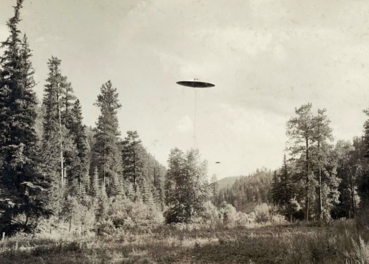

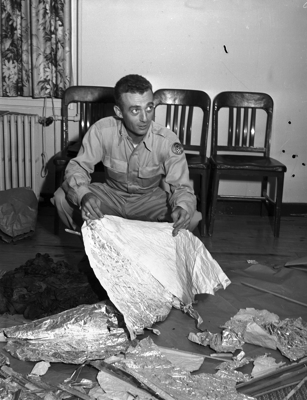


.jpg)