The Douglas XTB2D-1 “Skypirate” was a large, single-engine torpedo bomber built for use on the Midway class carriers during World War 2. At the time, it was the largest aircraft to be used aboard a carrier, dwarfing even two-engine designs. Unfortunately for the Skypirate, engine troubles, little support from the US Navy (USN), and numerous setbacks with the construction of Midway-class carriers nearly doomed it from the start. By the time it was airworthy, it was trying to fill an obsolete role which other aircraft, such as the TBF/TBM Avenger, already filled adequately. Work continued after the war, with several attempts to revive the program but it proved to be too costly and the Skypirate program was finally cancelled in 1947, with the two prototypes being scrapped in 1948.
History
With engagements such as the Battle of the Coral Sea and the hunt for the Bismarck, the effectiveness of torpedo bombers, such as the TBF/TBM Avenger and Fairey Swordfish, was clear. With the announcement of the large Midway-class carriers, the possibility of a new torpedo-bomber/scout bomber came about. In February 1942, a competition was put forward by the Navy for this role. The Douglas Aircraft Company, based in Southern California, proposed the Skypirate. The single-engine Skypirate was picked from eight different designs, most of which were two-engined. The Bureau of Aeronautics (BuAer) wasn’t expecting a single engine design to be submitted, assuming the specified massive carrying capacity would require a two-engine design. The program was being headed by Ed Heinemann as lead designer and Bob Donovan as the chief engineer, who would be on the project until the end.
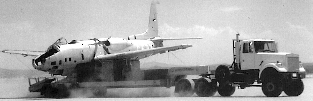
An impressive look at the massive Skypirate from the front.
In November of 1942, Douglas was given permission to begin production of two prototypes and a mockup of the XTB2D-1 (then called the Devastator II, before being changed to Skypirate). Delays in the development of the Midway class would continue to hamper the Skypirate throughout its life. The finished product was a formidable aircraft, capable of carrying four torpedoes from land or two torpedoes from a carrier, the former being four times the carrying capacity of the TBM Avenger. In March and May of 1943, the mockup was inspected and an order for 23 production aircraft was put in. This was enough for a single squadron to operate from a Midway carrier. Problems began about this time, with the delivery of engines and propellers being delayed. By 1944, the Skypirate was still not airborne and it was obvious it wouldn’t be operational anytime soon. With earlier torpedo bombers performing adequately, a lack of support from the Navy, most of the Japanese fleet in shambles and continued delays with the Midway class (which would eventually sail after the war), the 23 production planes were cancelled. On February 18th, 1945, the first Skypirate was rolled out of the production facility, being completed on March 13th and finally going airborne on May 8th. Neither of the prototypes had any defensive armaments, but they were tested with torpedoes and drop tanks. Although no production was to ever start, the Skypirates would continue flying until the end of the war. During one such flight in June of 1945, a Skypirate was damaged mid-flight, but the craft was brought down safely. Engine problems were a frequent issue with the Skypirate and propeller problems would ground it in August of 1945, not flying again until after the war.
Perhaps the most well known photo of the aircraft, the Skypirate prepares to land.
Postwar, the aircraft industry changed with the introduction of jet aircraft, thus eliminating the need for many prototypes being developed during the war. The Skypirate was no exception. With the torpedo bomber role now fading, the Douglas firm looked at other options to revive their Skypirate. Some ideas included using the Skypirate for an electronic warfare role or even as an anti-submarine aircraft (a role overtaken by another piston engine aircraft, the Grumman AF Guardian), but none of these propositions ever managed to become reality. As the Cold War was just beginning, the Skypirate program ended in 1947 and the 2 prototypes were scrapped in 1948.
Design
The Skypirate is most likely the largest single-engine aircraft to ever be designed for carrier operations. In comparison, the twin-engined B-25 Mitchell medium bomber measured around the same in length and width.
The 2nd prototype in flight, notice how the tail is shorter in comparison to the first prototype.
The initial Skypirate design had an internal bomb bay, which the prototypes dropped in favor of four external Mark 51 Mod 7 bomb hardpoints. These hardpoints could carry a range of weapons including 500Ib-2000Ib bombs, torpedoes, depth charges, mines or even incendiary bombs. The use of up to 4 Mk.13 Torpedoes (from land) were planned had it entered production. The Skypirate could alternatively carry up to 8,400Ibs of bombs. For offensive armament, the Skypirate had 4 M2 Browning machine guns in the wings. For defense, it had a Firestone model 250CH-3 remote turret behind the cockpit which carried 2 M2 Brownings and a turret in the back of the lower fuselage which carried a single M2 Browning. The lower turret was remotely fired through electronic control and powered hydraulically. Drawings indicate that Mark 2 Gun Containers could be added for extra forward firepower but none were ever attached during testing. 300 gallon drop tanks were also fitted during testing and could have been used had the craft been operational.
The sole mockup made alongside the 2 prototypes.
Along with such an impressive weapons payload, the Skypirate was full of advancements which would have improved its performance. To get such a large aircraft off the ground, the Skypirate was powered by a single Pratt & Whitney XR-4360-8, the largest radial engine ever built up to that time. The engine had a unique exhaust style that combined the exhausts in alternating rows to lower the effects of backpressure. Being a carrier-based aircraft, the Skypirate had folding wings as well as a catapult hook. The inclusion of a tricycle landing gear was also interesting, as it helped with bomb loading and carrier space. Most single engine aircraft of the time preferred using a tailwheel. The Skypirate had large flaps that extended the length of wingspan. The outer flaps served as ailerons while the midsection flaps were used as dive flaps. The dive flaps could also be lowered to help the aircraft cruise or assist in turning to help ease the stress off the aircraft when fully loaded. To assist with bombing or flight in general, a Type 3 Sperry vacuum-controlled, hydraulic autopilot was also to be added. A de-icing system was also added that pumped hot air over the wings and tail section.
The planned modifications of the prototypes are interesting to note. The 2nd prototype (Bu.36934) differed from the first, having a shorter tail of 8.6 ft, compared to the regular 10.5 ft tail of the original design. This was done most likely to conserve valuable space when inside a carrier. Along with these differences, plans to fit a jet engine in the fuselage of the 2nd prototype were made, but nothing ever came to fruition. The first prototype (Bu.36933) had a larger tail and was planned to be converted for the scout bomber role. These plans included adding cameras onboard. As with the jet engine designs, these also never came to be.
Variants
XTB2D-1 Bu.36933 – Prototype version, lacked any armament
XTB2D-1 Bu.36934 – The 2nd prototype. The tail was shortened to 8.6 ft. Also lacked any armament.
TB2D-1 – Proposed production version, 23 were ordered and planned production was to be 100 built every month. These versions were to be fitted with four .50 caliber machine guns in the wings, two in a Firestone power turret and one remotely controlled in the ventral hull. Eventually, the production versions were cancelled in favor of higher priority projects.
Operators
United States of America – Slated to be used aboard the Navy’s Midway-class carriers, with the end of the war and other setbacks, the XTB2D-1 was never used operationally.
The design team poses with the first Skypirate on rollout day.
TB2D-1 Specifications
Wingspan
70 ft / 21.3 m
Length
46 ft / 14 m
Height
22 ft 6 in / 6.9 m
Wing Area
605 ft² / 184.4 m²
Engine
1x 3,000 hp ( 2240 kW ) XR-4360-8
Propeller
1x 8 bladed Hamilton Standard contra-rotating propeller
Fuel Capacity
501 US gal / 1896 L
Oil Capacity
28 US gal / 106 L
Empty Weight
18,405 lbs / 8350 kg
Gross Weight
28,545 lbs / 12950 kg
Maximum Weight
34,760 lbs / 15765 kg
Rate of Climb at Sea Level
1,390 ft / 425 m per minute
Time to 10,000 ft / 3048 m
8.2 minutes (Normal) 10.2 minutes (Military)
Time to 20,000 ft / 6096 m
22.3 minutes (Normal) 26.5 minutes (Military)
Maximum Speed
340 mph / 550 km/h at 15,600 ft / 4755 m
Cruising Speed
168 mph / 270 km/h
312 mph / 500 km/h (with torpedoes)
Range
1,250 mi / 2010 km (Torpedoes)
2,880 mi / 4635 km (Maximum)
Maximum Service Ceiling
24,500 ft / 7470 m
Crew
1 pilot
2 gunners
Armament
4 Browning M2 machine guns mounted in the wings (1600rds)
Douglas XTB2D Skypirate Side ViewDouglas TB2D Skypirate Side View – With the Defensive Gun Pod
The last known photos of the Skypirates before being scrapped.One of the prototypes with mounted Mk-13 torpedoes.A back view of one of the prototypesFirst prototype of the Skypirate on the runway.An impressive look at the massive Skypirate from the front.Perhaps the most well known photo of the aircraft, the Skypirate prepares to land.The 2nd prototype in flight, notice how the tail is shorter in comparison to the first prototype.The sole mockup made alongside the 2 prototypes.The design team poses with the first Skypirate on rollout day.
The VL Pyörremyrsky prototype parked on a ramp [Colorized by Michael J.]The VL Pyörremyrsky (translates as Hurricane) was a prototype Finnish fighter plane designed to keep up with its contemporaries. It was to be domestically produced, using wood, but using the same engine as the Bf 109 G. Due to limitations brought about due to the war, only one prototype was produced and it wasn’t ready until the end of 1945.
Development and History
As Finland found itself still at war with the Soviet Union in 1942, with no end in sight, it turned to ways to bolster its military force. In order to become as self sufficient as possible, it was engaged in various projects for domestically designed and produced weapons systems. The VL Myrsky project was severely behind schedule and the air force realised that it would be outclassed by the newer Soviet aircraft by the time it reached production. With this in mind, it placed order number 2012/42 on 26th November 1942 for a new aircraft design, under the name Pyörremyrsky.
The State Aircraft Factory (Valtion Lentokonetehdas) was tasked with producing the new fighter and Captain of Engineering Torsti Verkkola was assigned chief designer of the team. The main premise was that the aircraft was to be made out of wood, as much as was possible, and that it was to be comparable with the German Messerschmitt Bf 109G. Verkkola used the Bf 109 as the base for his design, making modifications to allow it to be produced with local skills and materials. However, as the war dragged on, and the Finnish Air Force required more proven aircraft, as well as repairs to the planes already in service, the Pyörremyrsky found itself given a lower priority.
Profile of the Pyörremyrsky. Source: Warthunder forums
Upon the cessation of hostilities between Finland and the Soviet Union in September 1944, the Pyörremyrsky project had only a partially completed prototype and the Ministry of Defence (puolustusministeriö) cancelled the advance order of 40 aircraft, as well as the second prototype on the 29th September, but they did allow the first prototype to be completed. In Autumn 1945 the prototype, now christened PM-1 (which led to the nickname Puu-Mersu or Wooden Messerschmitt), was ready for pilot tests. On the 21st of November 1945, Luutnantti (Lieutenant) Esko Halme took off in PM-1 from Tampere-Härmälän airfield. The flight only lasted 25 minutes as part of the engines’ exhaust system came loose, forcing an emergency landing as Lt. Halme was unable to see through the exhaust blowing into his cockpit. Despite the incident, Halme reported good flying controls and characteristics. PM-1 would do 2 more test flights at Härmälän airfield before moving to Kuorevesi for Air Force testing. In total 31 test flights were performed, amounting to 27 hours of flight time. All 8 pilots reported the same, smooth and controlled flying characteristics, good speed and turning ability, however it was not quite up to the same performance of the Bf 109 G but close enough. The last flight of PM-1 was on the 22nd of July 1947, when Kapteeni (Captain) Osmo Kauppinen took off for a 20 minute general test flight. After this it was put into storage until it was officially removed from the Air Force’s rolls on the 1st April 1953. This was mainly due to the lack of ability to source new engine parts as part of the armistice Finland signed with the Allies forbade them from receiving military goods from Germany, as well as the decline of the piston aircraft as a fighter.
The Air Force didn’t want such a unique piece of Finnish aviation history to be scrapped however and ordered it to be preserved. It was sent to the State Aircraft Factory’s depot and was refurbished in the early 1970’s and sent to the Finnish Air Force Museum, where it is still on display.
The experiences learnt with the Pyörremyrsky were not totally in vain or wasted as the basic design was used in the development of the VL Vihuri fighter trainer.
Design
Access panels open revealing the engine. Source: Suomen Hävittäjät
Captain Verkkola used the Bf 109’s low-wing cantilever monoplane configuration as his base for the Pyörremyrsky. The Germans were also willing to supply the Daimler-Benz DB 605A-1 liquid cooled V12 engines and VDM 9-12087 three-bladed light-alloy propellers that were used on the Bf 109 series. It was also installed with a German produced Telefunken FuG 7a model of compact airborne receiver/transmitter.
The main body of the aircraft was built using the vast amounts of wood available to the Finns, with metal being used where absolutely necessary, like the cockpit and engine housing. While many believe the design is similar, if not copied from the Bf 109, there are many differences outside of just the materials used. The rear portion of the fuselage is of wooden monocoque design, with the horizontal stabilizers mounted at the near end, as opposed to the Bf 109’s which are mounted on the vertical stabilizer. The wings were of negative transverse V shape and covered in plywood panelling.
PM-1 at the Tampere trial airfield in the Summer of 1945. Source: Suomen Hävittäjät
Unlike the wing fuel tanks found in the Bf 109, the Pyörremyrsky had a single tank behind the cockpit, protected by a 10mm thick armoured plate. The landing gear was copied from the Bf 109 but the Finns made some changes to eliminate the narrow and problematic system that plagued the Germans. The tailwheel was also retractable, thus helping it with aerodynamics.
Due to wartime shortages, Finland was forced to rely on substandard replacement products. The use of Lukko glue was one of the main reasons for the failings in the VL Myrsky and so it has been suspected that the Pyörremyrsky would have suffered similar issues to its sister aircraft had it been pushed into service or flown for longer periods of time.
Armament was not fitted to the PM-1 but it was designed to be installed with a Motorkanone mounted 20 mm (.78 in) MG 151/20 cannon and two nose mounted synchronized 12.7 mm LKK-42 machine guns. It was also proposed that the wings would have provisions for two 100kg bombs each for fighter bomber duties, but it is not clear if the proposal was ever considered seriously.
Operators
Finland – The VL Pyörremyrsky was intended to be used by the Finnish Air Force.
VL Pyörremyrsky Sideart by EscodrionPM-1 in the Finnish Air Force Museum, next to a BF-109G. Source: WikimediaClose up of the undercarriage. Notice how they are copies of the BF-109 but close inwards. Source: WikimediaThe PM-1 cockpit. Taken at the Tampere trial airfield in the Summer of 1945. Source: Suomen HävittäjätProfile of the Pyörremyrsky. Source: Warthunder forums
Sources
Suomen Ilmavoimien Historia 14 Suomen Hävittäjät, Kalevi Keskinen, Vammalan Kirjapino Oy 1990, Suomen Ilmavoimien Historia 17 LeR2, Kalevi Keskinen, Edita OYJ 2001, www.ilmailumuseot.fi, Valtion Lentokonetehtaan historia – Osa 2: Tampereella ja sodissa 1933–1944. Jukka Raunio, 2007, Images: Side Profile Views by Escodrion – https://escodrion.deviantart.com, Colorized Images by Michael J.
The PZL P.50 Jastrząb (Hawk) entered development in 1937 as a replacement for the outdated PZL P.11 and PZL P.24 fighters. Very little was known about the aircraft until relatively recently, with only a few photographs and documents about this aircraft surviving World War II. Most of what is known at the time of writing is based on accounts and sketches from PZL engineers years after the war and mostly based on memory, which is not the most reliable form of historiographic evidence. Ultimately, the project was cancelled in March of 1939 due to dissatisfaction with its underpowered radial engine, despite an attempt being made to fit an inline vee engine to the aircraft in the form of the PZL P.56 Kania (Kite).
History
In the latter half of 1936, plans to replace all of Poland’s PZL P.11 single-engine fighters with the twin-engined PZL P.39 heavy fighter were abandoned, and the need for a maneuverable single-engine interceptor was recognized. Briefly, the PZL P.24 was considered in order to fulfill this role, but as it did not offer much of an improvement over the P.11, it was ultimately decided that an entirely new design was needed.
Wsiewlod Jakimiuk, the head of PZL’s fighter team, submitted a proposal in autumn 1936 featuring “an advanced low-wing monoplane which offered improved all-around performance and great scope for future development” (Cynk, p. 259). The aircraft resembled the American Seversky/Republic fighter designs. One of the things that Jakimiuk focused on in the design of this aircraft was to allow upgrading to larger and more powerful engines to be a simple task to accomplish at any later time.
Ultimately, after a heavily-protracted design process plagued by numerous issues, the aircraft never saw combat and only 32 airframes had been built before Poland was invaded by Germany and the USSR in September 1939, but 30 of these were not completed.
Design
This image shows Count Ciano of Italy inspecting the P.50/I. Note the cowling’s radial engine cooling system.
In the fall of 1937, the design, now called the PZL P.50 Jastrząb and powered by a British 840-horsepower Bristol Mercury VIII radial engine, was approved and two prototypes were soon built. The first prototype, called the P.50/I, was designed to take engines up to 1,200-horsepower while the second prototype, the P.50/II, was designed for engines of up to 1,600-horsepower. Both versions were to be armed with four 7.7-millimeter machine-guns in the wings although, confusingly, the few images of the P.50/I show two of these guns in the forward fuselage instead. The P.50A production version of the P.50/I was envisioned to have a top speed of 310 miles per hour (500 kilometers per hour) at 14,100 feet (4,300 meters).
The Polish Aviation Command almost immediately ordered 300 aircraft and paid for the first 100 in advance, with the first 50 expected to be delivered by September 1939. In order to speed up development The Dowty Company of Britain was contracted to build the landing gear for the prototype, while PZL and the Czech Avia company would design the production aircraft’s landing gear. Dowty delivered the landing gear over four months late, and the P.50/I Jastrząb prototype, still utilizing the Mercury engine, did not even fly until February 1939.
During the P.50/I’s initial flight trials, it was discovered that the desired performance parameters were far out of reach. The top speed at full load was only 274 mph (442 kph). It also handled low-speed turns very poorly and had a tendency to wobble at top speed. Curiously, it was discovered that the engine was unable to produce full power under any circumstances. It was not until May that it was realized that the carburettor air intake was too small. After enlarging the intake and improving the tail and wing surfaces, the aircraft’s performance was improved. In August, the aircraft finally reached its desired speed but, by the time the war began in September, the aircraft was still a long way from being ready for service. The only known photos of the P.50/I come from a visit in February 1939 by the Italian Foreign Minister, Count Galeazzo Ciano.
Developed alongside the P.50/I was the P.50/II, which had been completed in the spring of 1939 and was still waiting for an engine by the time of the invasion in September. The P.50/II differed greatly from the P.50/I, so much so that it is believed to have received a new designation just before the war began. The canopy was an all-round-vision hood, somewhat similar to the Soviet Yak-1b. The P.50/II also included provision for additional fuel tanks and a 660-pound (300kg) bomb, and two 20mm cannons were added to the wings. The two machine-guns which were in the fuselage of the P.50/I were also moved to the wings. The powerplant was supposed to be the PZL Waran radial engine, capable of up to 1,400hp, with the intended top speed of the P.50/II being 350mph (560kph). However, development of the engine was far behind schedule and it was estimated that it would not be ready before the middle of 1940. In a desperate search for a suitable engine, several different options were considered. These included the 1,375hp Bristol Hercules and the 1,400hp Gnome-Rhone 14N, again both radial engines. In the end, the Hercules appears to have been chosen, and it was around this time that the P.50/II received its new designation.
This angle of the same visit by Count Ciano shows off the two machine-guns in the forward fuselage.
There was one more derivative of the P.50, beginning in late 1938. Political upheaval was ongoing in the Polish Air Force high command, and General Ludomil Rayski, who favored radial engines, was coming under heavy criticism and was nearing replacement by General Jozef Zajac, who favored vee engines. This replacement would eventually take place in March 1939. Jakimiuk, the designer of the P.50, anticipated this shift and proposed a Jastrząb adapted to take an inline engine. The aircraft was given the designation P.56 Kania (Kite) and was to be powered by the 1,200hp Hispano-Suiza 12Y, and later by the improved 1,600hp Hispano-Suiza 12Z. However, another PZL designer, Jerzy Dabrowski, submitted a competing design bearing the designation P.62, and this design was preferred over the P.56. The P.56 was ultimately cancelled in the summer of 1939.
When General Rayski was ousted from the command of the Polish Air Force in March 1939, the P.50/I was still having severe problems. His replacement, General Zajac, canceled all production of the P.50 almost immediately. 30 P.50A airframes had begun construction at the W.P.1 plant in Okecie and, after the P.50/I began to show improvement, construction was permitted to continue on these aircraft only. Because of the unsatisfactory results of the Mercury engine, plans were made to power the very first of these production aircraft with the 870hp Gnome-Rhone 14Kirs, and this aircraft was very close to being ready in September 1939. This was to be a sort of test aircraft for an improved version of the P.50A, the P.50B Jastrząb B. There were also plans to mount the 1,100hp Gnome-Rhone 14K or the 1,000hp Pratt & Whitney R-1830 Twin Wasp, although these never came to fruition.
“The Hawk Which Would Never Prey”
On September 5th, 1939, the PZL factory in Warsaw was evacuated. Test pilot Jerzy Widawski attempted to escape with the P.50/I prototype, but was accidentally shot down by Polish anti-aircraft guns. Five pre-production P.50A airframes and the P.50/II prototype, including the aircraft intended to be equipped with the 870hp engine mentioned earlier, were moved out of the Okecie plant on September 3rd. These were captured by the Germans and scrapped in 1940, bringing a final end to the P.50 Jastrząb project.
Variants
PZL P.50/I Jastrząb – Initial prototype of the PZL P.50 series. Powered by an 840hp Mercury VIII engine, the top speed was intended to be 310 mph, but it only ever reached 275 mph. Armament was four 7.7mm machine-guns, with two in the forward fuselage and two in the wings. One produced, first flew in February 1939.
PZL P.50A Jastrząb A – Planned production version of the PZL P.50/I. 300 were ordered, but only 30 built, all incomplete by the time of Polish capitulation. Fuselage was changed to a razorback rear, akin to the American P-47. It is unclear whether the fuselage machine-guns were moved to the wing, as documents imply they were but sketches of the aircraft still show them in the fuselage. Top speed had been improved to 310 mph (500kph).
PZL P.50B Jastrząb B – Planned development of the P.50A with a more powerful radial engine. One P.50A was planned to fit an 870hp Gnome-Rhone 14Kirs engine as a sort of testbed for the P.50B, but that is all that is known about this variant.
PZL P.50/II Jastrząb II – Second prototype developed alongside the P.50/I prototype as an all-around upgraded version. The canopy was changed. A 660 lbs (300 kg) bomb was added, along with two 20mm cannon to the wings. The engine was upgraded to the 1,400hp PZL Waran engine, giving a projected top speed of 350 mph (560 kph) . Only one was produced, without the engine, and never flew.
PZL P.56 Kania – Planned development of the P.50A Jastrząb A using either a 1,200hp Hispano-Suiza 12Y or 1,600hp Hispano-Suiza 12Z inline Vee engine. None produced.
Operators
Poland – 300 copies of the P.50A type were ordered, with only 30 incomplete airframes + 1 P.50/I prototype produced. Did not see service. A single P.50/II prototype also existed, but the type was never ordered.
PZL P.50A Jastrząb A Specifications
Wingspan
31 ft 9.875 in / 9.7 m
Length
25 ft 3.125 in / 7.7 m
Height
8 ft 10.25 in / 2.7 m
Wing Area
208.83 ft² / 19.4 m²
Engine
One 840hp (648.8kW) Bristol Mercury VIII nine-cylinder radial engine
Empty Weight
3,748 lbs / 1,700 kg
Maximum Takeoff Weight
5,511 lbs / 2,500 kg
Maximum Speed
310.6 mph / 500 kmh
Range
466 mi / 750 km
Maximum Service Ceiling
14,107 ft / 4,300 m
Crew
1 pilot
Armament
Four 7.7mm KM Wz 36 machine-guns mounted in the wings OR two in the fuselage and two in the wings
Provision for an unknown weight of bombs, possibly 220.5lbs (100kg), to replace two wing machine-guns
Gallery
Side view of the P.50/I illustrated by Ed JacksonSide view of the P.50 as it would have appeared in service by EscodrionThis blueprint of the P.50/I was drawn was based off of a PZL engineer’s sketch of the blueprints after the planes had been captured or destroyed.A period illustration of the P.50This photo shows one of the 30 incomplete P.50A’s, captured by the Germans after the invasion of Poland in 1939. They would later be scrapped.A small image with the Count Ciano of Italy inspecting the P.50/I. Note the cowling’s radial engine cooling system.This angle of the same visit by Count Ciano shows off the two machine-guns in the forward fuselage.Italian Foreign Minister Count Galeazzo Ciano inspects the P.50/I prototype in Warsaw, February 1939.
Polish aircraft historian Zabytki Nieva discusses the PZL P.50. Audio is in Polish with English subtitles available.
Video made by the author specifically to accompany this article.
The VL Myrsky (translates as Storm) is a Finnish domestically produced fighter. 51 were manufactured between 1941 and 1945 and it was one of the fastest aircraft in the Finnish inventory at the time. Despite having good performance on paper, it was plagued with issues and uncertainty. It would be withdrawn from service in 1947 having served in numerous roles such as interceptor, fighter-bomber and reconnaissance.
Development
Finland, being a small and newly independent nation, suffered from severe financial limitations and this included funds allocated towards its air force. However, the situation in 1930s Europe was not looking promising and in 1937 major funds were allocated to the defence budget for modernisation and expansion of Finland’s armed forces. By 1938, Finland had bought 7 Fokker D.XXI fighters, as well as the manufacturing license to produce more. However, Head of the Defence Council, Marshal Mannerheim, highlighted the need to produce a local fighter in order to lessen reliance upon foreigners in case of war. Major General Jarl Lundqvist, commander of the Finnish Air Force, replied that alternatives were being sought out but that high prices of specialised machinery, as well as many nations gearing up for war themselves, needed to produce such aircraft put limitations in place.
In early 1939, the Air Force made a survey of various aircraft designs and, upon completion in April, invited the State Aircraft Factory (Valtion lentokonetehdas) to ‘negotiations in Tampere on the construction of a prototype of a fighter machine in Finland’. On 4th May 1939, VL presented 5 different designs using the Bristol Taurus engine to the Ministry of Defence (puolustusministeriö) .
The Ministry of Defence placed contract 1094/39 with the State Aircraft Factory on 8th June 1939, which called for 33 aircraft to equip a fourth squadron. The design chosen was to be powered by the Bristol Taurus III 14-cylinder two-row radial aircraft engine, have semi-elliptical 19 square meter wings and retractable landing gear with allowances for ski pods. Its initial appearance was similar to the VL Pyry trainer which was undergoing prototype trials at the time.
Myrsky conducting patrols over ice floes
However, when the United Kingdom declared war upon Germany in September 1939 due to its invasion of Poland, the possibility of acquiring the Bristol Taurus disappeared and a solution was needed. The design team thought the best replacement was the Pratt & Whitney R-1830-S3C3-G Twin Wasp and an order was placed. Due to the inevitable delays and mounting pressure in Europe, the Air Force placed an order for 35 Fiat G.50s to equip the fourth squadron. On 30th November 1939, Soviet forces attacked Finland in the opening moves of what would become known as the Winter War. This action put paid to many of Finland’s rearmament plans, including the Myrsky development, with an official order of termination being issued by the Ministry of Defence on 8th December (which seems to have not been fully complied with due to archival material showing dates during the Winter War).
After the conclusion of the Winter War on 13th March 1940, Finland saw itself in a critical situation which was further enhanced by the actions of Germany in Denmark and Norway. In April, the Finnish domestic programme was restarted with an emphasis upon speed, which led to more delays on the design. Finland reached out to both the US and Germany for more powerful engines, like the American Pratt & Whitney R-2800 Double Wasp and German BMW 801. However, the US put an export ban on war material in July and Germany was unwilling to sell any materials except captured ones like the Curtis 75A Hawk and Morane Saulnier MS 406. This then led to the placement of the programme in suspension until the winter of 1940.
On 20th December 1940, contract 1621/40 was issued ordering a prototype. About 60,000 hours went into the design phase, with 77,000 manhours going into the manufacture of the prototype. The original goal was for a working prototype to be completed in early July 1941 but, with the outbreak of the Continuation War, the project saw delays again. The prototype was finally completed in December and made its maiden flight on the 23rd December 1941 by Lieutenant (Luutnantti) Erkki Itävuori. A few redesigns were made during this second stage of development, the most notable being the copying of the tailplane of the Brewster Buffalo F2A. Given the serial MY-1, the prototype suffered from engine difficulties, as well as displaying a tendency to yaw. Also, it had a high wing loading (194 kg/m2) which meant that its rate of climb and maneuverability were compromised.
Myrsky in flight above the runway
The MY-1 was redesigned and modified in order to fix the issues highlighted in the small scale test flights. The yaw was resolved by redesigning the whole rudder with an enlarged area and removing the supports from the horizontal stabilizers. Weight was reduced by changing the fuel tank, changing the engine gills and a few other minor changes, freeing up 317 kg and decreasing the wing loading to 175 kg/m2. The Hamilton Standard propeller was replaced by a locally designed VLS 8002 adjustable propeller and the exhaust pipes were modified to attain better thrust. Overall the MY-1 prototype went through four major modification stages and attained a final maximum speed of 519 km/h at 3250 meters altitude and a climb to 5000 metres in 6.5 minutes. While not perfect, the aircraft was seen as satisfactory. MY-1 took its last flight on 26th November 1943 with Captain (Kapteeni) Kokko, ending with a total logged time of 142 hours and 20 minutes in 162 flights.
Pre-Series Production
Prototype Mockup Myrsky
Before the prototype’s test flights had all finished the Air Force placed an order for a pre-series of three aircraft to be produced on 30th May 1942. The idea was for these three aircraft to help test concepts and make mass production faster when the time came. These craft were serialled MY-2 to MY-4 respectively. MY-2 was completed in April 1943, it had thinner wings, Hamilton Standard metal propeller, pneumatic brakes and was the lightest Myrsky at 2150kg empty. It was destroyed on 6th ofMay 1943 when its engine failed from lack of fuel, Captain P.E. Sovelius was injured during the crash landing. MY-4 was finished 5th June, it boasted a thicker wing, easier removable engine, better cowlings, hydraulic brakes and the VLS 8002 adjustable propeller. It weighed in at 90 kg more than the MY-2, or 2 240 kg. MY-3 was completed on the 11th July, it weighed in at weighed 2 210 kg but was similar to the MY-2 except for slight modifications. This series was known officially as the I Series (I Sarja).
MY-3 made a belly landing on 5th August 1943 as the landing gear malfunctioned. During the repairs, they patched up the fuselage with plywood, adding another 10 kgs. Splines were added to the propeller spinner to help reduce overheating and these were carried over to the production models. After repairs the MY-3 was cleared for more flights, on 19th November 1943, during a test dive, aeroelastic flutter broke off the wings and then the tail, plunging the aircraft into the ground at 855 km / h. Warrant Officer (Vääpeli) Aarre Siltavuori was killed. Investigation after the event concluded that the wings needed to be reinforced and that dive speeds should not exceed 600 km/h.
MY-4 was continually used for testing and its armament layout was the one used in the production series. In February 1944 it was issued to No. 26 Fighter Squadron (Hävittäjälentolaivue 26) to assess its viability as a combat aircraft, it immediately caused problems as the 20 pilots who took turns to fly it noticed issues with its flying characteristics in comparison to their Fiat G.50s. On the 17th March, during a diving test the plane was attempting to spin to the right and lieutenant Jaakko Marttila struggled with the aircraft, under such stress the right wing finally broke at two metres from the tip, causing the plane to enter into an uncontrollable spinning dive that killed the pilot.
Production Series and the Continuation War
Crew posing with their Myrsky
On the 18th August 1942, contract 1952/42 was issued that specified a production of 50 Myrskys, split into two batches. A three aircraft pre-series, as covered above, and a production series, to be called the II series, of 47 aircraft to be serialized as MY-5 to MY-51. MY-5 was completed in December 1943 and MY-51 was finished in December 1944.
The Myrsky continued to show problems during dives, MY-6 crashing due to the left elevator breaking loose when it reached 640 km/h in June 1944. This caused an order to reinforce all elevators, both on completed models and those going through production. Due to the numerous delays, the now adequate performance, as well as the many Bf 109’s supplied by Germany, the Fighter squadrons were not interested in the Myrsky. Indeed, only No. 26 Squadron were equipped with Myrskys to replace their aging Fiat G.50s but these were soon replaced by Brewster F2A Buffalo s. Orders from Air Force command saw the Myrsky banned from crossing the front lines due to their poor performance against contemporary Soviet fighters. Instead the reconnaissance squadrons (Tiedustelulentolaivue) gratefully received these speedy and modern aircraft, by comparison to their previous machines. No. 12 Reconnaissance Squadron became the first Myrsky reconnaissance unit in July 1944, there first mission was on the 9th August with a patrol flight in the Suistamo area where they attempted to intercept a flight of Yak-7 fighters with no results. The 22nd August saw the Myrskys baptism of fire when a 6 plane reconnaissance mission came across 3 Yak-9s at Mantsi. Lieutenant Linden scored confirmed hits upon one Yak but failed to bring it down, during the return flight Captain Virkkunen scored hits upon a La-5 but still not confirmed kills (after the war it was confirmed the Yak made an emergency landing at its home base and the La-5 suffered from damaged pressure systems).
During the later design phase, it was decided that the planes should be able to mount two 100 kg bombs. Pilots at the Tampere testing facility practiced the concept using weight concrete bricks but due to the planes relegation to reconnaissance, it was believed that the racks would not be used. However on the 3rd September, Captain Oiva Tylli led a six plane formation to bomb the Soviet 7th Army Corps headquarters at Orusjärvi (this saw the lifting of the crossing frontlines orders, as the HQ was some 35-40km behind the Soviet lines). 11 of the 12 bombs detached from their racks and damaged the lightly defended headquarters and the planes flew out of there before they could be intercepted. Later that same day the last combat mission of the Mysrky during the Continuation War took place, a four Myrsky flight was sent on a patrol at Sortavalan-Lahdenpohja but returned empty handed.
On the 4th September 1944 a ceasefire came into effect as a result of negotiations between the Finnish and Soviet Governments. No. 12 Reconnaissance Squadron was ordered to fly to Joroinen and await further orders. At the closing of hostilities, 44 of the 47 II series aircraft were completed. One squadron, No.12, was fully equipped, and another squadron, No.16, was partially equipped with six.
Lapland War and Peace
One of the stipulations of the ceasefire was the cessation of diplomatic relations with Nazi Germany and the expelling of Wehrmacht forces from Finnish territory by the 15th September 1944. With over 200,000 troops residing in Finland, as well as the essential nickel mines in Lapland, the Germans were both incapable and unwilling to withdraw in such a quick manner. This led to the outbreak of what became termed ‘The Lapland War’ (Lapin Sota).
A Finnish force of some 75,000 (4 Divisions as well as some attached elements) was assigned to the task of pushing the Germans from their land. A special air detachment was formed, Lentoryhmä Sarko, with the mission to support ground operations. 2nd flight of No. 12 Reconnaissance Squadron was subordinated to No. 26 Fighter Squadron at Kemi. Soon Myrskys were performing reconnaissance missions over Lapland but the severe weather soon put paid to any more flights by the Myrskys and on the 23rd November the last flight in combat conditions by a Myrsky was completed.
After the formalisation of the Moscow Armistice in September 1944, the Air Force was put in to peacetime strength in December. This saw a major reduction and restructuring of the Air Force as a whole. No.12 Reconnaissance Squadron became No.11 Fighter Squadron, and No.16 Reconnaissance Squadron became No.13 Fighter Squadron, these squadrons were amalgamations of other units and so were also equipped with BF-109G-2s and Curtiss Hawk 75As. The Myrskys continued to serve in these fighter units but were still subject to accidents, especially from stalling, which saw a suggestion to modified the wings with slots. MY-50, which was never issued to the air force but remained at the factory’s hanger, was modified with slotted wings but nothing went further. On 9th May 1947, Captain Kauko Ikonen, took MY-28 out for a training flight when it suddenly entered into a dive and broke up in the air. The plane plunged into the soft clay and was not recovered, No.11’s commander ordered a grounding of the entire Mysky fleet, which was confirmed by the Wing’s headquarters later that day.
The last flight of the Myrsky took place on 10th February 1948, when MY-50, was allowed to fly from its test hanger to Tampere for storage but as it came into land, it overshot the runway and landed on its belly.
Today there is a restoration project to bring back MY-14 to a fully reconditions state for display at the Finnish Aviation Museum. The project has reach a stage where it could be unveiled to the public for Finnish Air Force 100th anniversary air show in June 2018.
Design
When the original order went out for the design, Arvo Ylinen (head of the design-bureau), Martti Vainio (aerodynamics), and Torsti Verkkola (structural design), were assigned the task of designing the new plane.
They decided to combined the learning they had from the Pyry trainer with the experience of licensed building of modern aircraft like the Fokker D.XXI. This allowed for not only cheaper design and production but also allowed for the design to be tweaked to Finnish desires. Due to the limitations upon Finnish industry (both due to its economic and geographical locations), it was decided that the design would be a combination of wood and metal.
The fuselage used a metal wire frame which was then covered with fabric and plywood, while the wings made from plywood and covered in a birch veneer (called Kolupuu).This did allow for cheaper production and lighter construction but contributed to the breaking of the wings upon reaching certain speeds. Because of the rarity of duraluminium, it was decided that the Myrsky should have none of it in its construction (but because of problems finding a suitable replacement, it was used in certain aspects of the machine like the flaps), instead aluminum (which had been bought from Norway and Sweden before the war) would be used sparingly and combined with specialised wooden parts.
The generalised design was the conventional piston aircraft, with a low wing attached just forward of center. The cockpit suffered from the same issues that many of its contemporaries did, in that the long nose limited its forward vision, but it is have excellent side visibility. The armament was four VKT 12,70 mm LKk/42 machine guns, mounted two per side of the engine, these were synchronised to fire through the propeller. It was also decided to add a hard point under each wing which would allow for an additional fuel tank or a 100kg bomb to be used.
Due to wartime shortages, Finland was forced to rely on substandard, replacement products. The use of Lukko glue was one of the main reasons for the failings in the Myrsky. It was not of the same quality as pre-war glue and did not stand up to rain, frost and humidity (a common occurrence in Finland), and would require more man hours to keep the aircraft in a flyable condition.
Losses
During its lifespan, the Myrsky was involved in 48 separate incidents, 10 of these resulted in the complete loss of the aircraft and 4 pilots died as a result.
MY-2 was destroyed on 6th May 1943 when its engine failed from lack of fuel, Captain P.E. Sovelius was injured during the crash landing.
MY-3 was destroyed on 19th November 1943 when aeroelastic flutter broke the wings of the aircraft. The Pilot, Warrant Officer Aarre Siltavuori was killed
MY-4 was lost on 17th March 1944 during a training flight. The plane entered into a dive which then broke one of the wings. Lieutenant Jaakko Marttila died in the crash.
MY-29 was destroyed on 4th September 1944 during a transfer flight. Lieutenant Aulis Kurje lost control of his aircraft when the engine overheated and cut out. The plane crashed into the wood, causing the seat to break free, killing the pilot.
MY-25 was destroyed on 13th November, 1944. During a reconnaissance flight near Kemi, MY-25s engine cut out forcing Lieutenant Berndt Schultze to perform a crash landing, he sustained minor injuries.
MY-27 was destroyed on 26th January 1945. After a crash landing on the 23rd January 1945, it was decided to fly the aircraft down to Pori, during the flight the fuel ran out. Warrant Officer N. Satomaa crashed the plane into a forest near Veteli. He was badly wounded but survived.
The MY-26 was destroyed 25th December, 1945. Due to malfunction, Staff Sergeant (Ylikersantti) E. Tähtö was forced to crash land in Pori. He walked away with minor injuries.
MY-24 was destroyed on 11th December 1945. Sergeant (Kersantti) Onni Kuuluvainen lost control of his craft when performing a speed correction. After several attempts to recover the plane he parachuted to safety. The plane crashed into a farmer’s field in the Pori area.
MY-5 was destroyed on November 20th, 1946. Lance corporal (Korpraali) Erkki Jaakkola was forced to make a crash landing in a field after his plane suffered from a fuel feeding problem after climbing to 7,000 metres.
MY-28 was destroyed on 9th May, 1947. During a training session, Captain Kauko Ikonen lost control of his plane, which then broke into pieces and smashed into the ground at Nakkila. This caused the entire Myrsky fleet to be grounded.
Variants
VL Myrsky – Myrsky prototype. Serialled MY-1. It differed from the later versions in being armed with two fuselage mounted 12,7mm mgs and four wing mounted 7,7mm mgs in the wings. It also had the Pratt & Whitney R-1830-S3C3-G Twin Wasp engine. The altitude stabilizers were originally supported but removed during the stage III modifications. Its undercarriage is also 15cm longer, giving it a more angled appearance when on a flat surface. Only 1 produced
VL Myrsky I – The pre-series production. Used to test ideas from the prototype, and to help gain experience in production. Each one was slightly different with various modifications. These were powered with the Pratt & Whitney R-1830-SC3-G Twin Wasp engine. They had more fabric pieces than their production counterparts. 3 produced.
VL Myrsky II – The production series. Taking the experience gained in the prototype and pre-series phases and putting it into practice. Using the R-1830-SC3-G Twin Wasp engine, it was modified with different gears to produce 1,155 horsepower on take-off. 47 were built.
VL Myrsky III – In March 1944 an order for 10 improved Myrsky versions was given to the State Aircraft Factory. This order was cancelled on 30th September 1944 and the whole series was cancelled on 30th May 1945.
Conclusion
The VL Myrsky was the embodiment of Finnish thinking, small and quick, hard hitting but light. The domestic fighter programme would not only bring more jobs to the locals but would be a point of pride that Finland could stand its own if it needs be. Also, as it was the only domestic fighter to see service during the war, it became a symbol of pride of Finnish independence.
Because of the many delays in its production, by the time it arrived on the front lines, the war had stabilized into what is termed ‘asemasota kausi,’ or The Trench War period. This meant that the war was much quieter in comparison to the other fronts that the Soviets were fighting on. The fighter pilots reports upon its mediocre performance in terms of speed and maneuverability in comparison to the Yaks and Las they were facing but the reconnaissance pilots reported positively upon these characteristics. It occupied the second fastest serving aircraft in the Finnish Air Force (only the BF-109 being faster) and its cockpit ergonomics were favorable and the pilots enjoyed its ground handling properties, thanks to the wide undercarriage.
It was far from the perfect aircraft, at low speeds it had a tendency to stall to the left. Its batteries tended to drain quickly if not pulled from the aircraft when not in use and the metal parts were prone to rusting. The inferior quality of the glue used during the war meant that more maintenance was required to keep the airframe flight worthy, reports of seams on the wing surfaces, rudder and elevators opening were a common occurrence. Pilots, both fighter and reconnaissance, reported upon the armament being too weak to take on the modern Soviet fighters and that due to the engine being governed, the plane was ‘too slow’ for what it should have been.
Operators
Finland – The VL Myrsky was only used by the Finnish Air Force
VL Myrsky II
Wingspan
36.08 ft / 11.00 m
Length
27.39 ft / 8.35 m
Height
9.84 ft / 3.00 m
Wing Area
193.75 ft² / 18.00 m²
Engine
1x Pratt & Whitney R-1830-SC3-G Twin Wasp modified (1,155 hp)
Maximum Weight
7,083 lbs / 3,213 kg
Empty Weight
5,152 lbs / 2,337 kg
Climb Rate
49.21 ft/s / 15.00 m/s
Maximum Speed
292.04 mph / 470 km/h at Sea Level
332.43 mph / 535 km/h at 10830 ft / 3,300 m
Maximum Service Ceiling
31,170 ft / 9,500 m
Crew
1x Pilot
Armament
4x 12.7mm VKT 12,70 Lkk/42 (960 Rounds Total)
Ordinance
2x 220.5 lb /100 kg Bombs or
2x 39.62 Gal / 150 L Drop Tank
The Hakaristi (Finnish Swastika)
It is important to note the use of the ‘Swastika’ on Finnish military equipment due to the confusion of its application.
Finland first adopted the Swastika (known as Hakaristi, broken cross, in Finnish) on the 18th March 1918, thanks to a donated aircraft that arrived earlier that month from Swedish Count Eric von Rosen (who used a blue swastika as his personal symbol). The Hakaristi became a national symbol from that moment, being used on everything from the Medal of the War of Liberation, the Mannerheim Cross, tanks, aircraft, to even a Women’s auxiliary organisation.
It became part of the official Air Force insignia, being used as an identification symbol as well as on certain badges and awards, from its inception in 1918 and today is still maintained upon certain symbols like the Standards of Commands.
Due to this early adoption, it has no association with the Nazi regime and the usage of such a symbol by both parties is only a coincidence.
Gallery
VL Myrsky – MY-50 by Brendan MatsuyamaVL Myrsky MY-5 by Brendan MatsuyamaPrototype Mockup MyrskyMyrsky in flight above the runwayCrew posing with their MyrskyMyrsky conducting patrols over ice floesMyrskys hangared for maintenance
United States of America (1944)
Prototype Escort Fighter – 2 Built
The first XP-81 powered by the TG-100 engines (Convair)
The Consolidated Vultee XP-81 was a prototype mixed power fighter developed in late 1943 by the Consolidated Vultee Aircraft Corporation in order to meet an Army Air Force requirement calling for a high altitude escort fighter. Plagued by slow development and engine problems, the XP-81 would never see active service and development would be terminated in 1947. Despite this, the XP-81 still holds a distinct place in history as America’s first turboprop engine plane to fly and the world’s first plane to fly with a turboprop engine and a jet engine together.
History
With the formal introduction of the Boeing B-29 Superfortress on May 8th of 1943, it would be clear that a high altitude escort fighter would soon be needed to accompany the Superfortress on its bombing missions over the Pacific. In the summer of 1943, this need was realized and the United States Army Air Force (USAAF) issued a list of design requirements that consists of the following:
1,250 mile (2,012 km) operating radius
Fuel for 20 minutes of combat plus reserve fuel supply for landing
Cruising speed of 250 mph (402 km/h) at 25,000 ft (7,620 m)
Maximum speed over 500 mph (804 km/h)
Combat ceiling of 37,500 ft (11,430 m)
Climb rate of 2500 fpm (feet per minute) / 762 mpm (meters per minute) while at 27000 ft (8230 m)
Two engines*
12 ° angle of vision over the nose
* – The USAAF recommended that the designers use a two engine setup consisting of a propeller engine for long range flights while complemented by a jet engine for high speed combat situations.
Promotional illustration of the XP-81 showing a diagram of the XP-81. (Consolidated Vultee)
Interested in this proposal, the Consolidated Vultee Aircraft Corporation, later known as Convair, began work on an aircraft which would meet the specifications, appointing Charles R. Irving, who was a chief engineer of the Vultee Field Division and Frank W. Davis, the assistant engineer, who was also the chief test pilot, as the leaders of the design team. The project was known as the “Model 102” within Consolidated Vultee. In the early stages of development, the designers faced a dilemma of engine selection. The Pratt & Whitney R-2800 Double Wasp radial engine was considered, as was the General Electric TG-100 turboprop engine. After some evaluating and testing however, the TG-100 was selected as it was deemed to have superior performance for combat and cruising situations. As for the jet engine in the rear, a relatively straightforward choice to mount a General Electric J33-GE-5 (also known as I-40) jet engine was made. After a couple of months of development, Consolidated Vultee submitted a preliminary design proposal to the United States Army Air Force in September of 1943. Relatively interested in this design, the plane was given the greenlight for further development and received the designation “XP-81” by the Air Material Command.
Detailed work on the XP-81 began in January 5th of 1944 and on January 18th, Consolidated Vultee was given the contract (no. W33-038-ac-1887) by the USAAF worth about $4.6 million to construct two flying XP-81 prototypes and one airframe for ground testing under the USAAF project name “MX-480”. Another contract followed on June 20th of 1944 worth $3,744,000 for the two flying examples, the airframe and the testing data. The contract was later modified to include 13 YP-81 under the project name “MX-796”. The construction of the first XP-81 prototype would begin on January 20th at the formerly independent Vultee aircraft factory in Downey, California but problems soon surfaced. Some time in April, the Air Material Command was notified that there would be a delay in the delivery of the TG-100 due to a couple of technical difficulties. As such, construction of the first prototype was delayed as the designers sought out an alternative engine to replace the TG-100 in June.
Consolidated Vultee flight test crew poses with the first XP-81 prototype. (XP-81)
The Packard V-1650-3 (some sources state V-1650-7), which was the American copy of the British Rolls-Royce Merlin engine, was selected to fill in the gap and the USAAF promptly provided Consolidated Vultee with such an engine taken from a North American P-51D Mustang. Within a week of receiving the engine, Consolidated Vultee engineers were able to install it after making considerable structural modifications to the first prototype’s airframe. A radiator similar to that of the Lockheed P-38J’s “beard” radiator would also be mounted on the XP-81, under the propeller spinner. Unfortunately for the designers however, the change of powerplant would add 950 lb (431 kg) to the plane while taking away 960 hp at takeoff and 1720 hp at top speed. With the relatively slow development, the first XP-81 prototype would finally be completed in January of 1945 bearing the serial number of “44-91000”.
Although the aforementioned issues with weight gain and horsepower loss were present, the Packard engine powered XP-81 was still deemed safe for flight tests, and as such, the first XP-81 prototype was prepared for test flights at Muroc Dry Lake in California and finally took to the skies on February 7th of 1945 with Frank W. Davis in the cockpit. Amazingly enough, 46 test flights were made with the Packard engine and it accumulated a total of 47.75 flight hours. In the testing phase it was noted that with the Packard engine installed, the XP-81 had poor directional stability at low speeds and the occasional splatter of oil on the windscreen by the propellers. Plans to replace the Packard engine were brought up on May 18th of 1945 when the TG-100 turboprop was finally available. The conversion was completed and the first prototype was returned back to Muroc for more tests on June 11th. Due to the new engine installation, extensive ground work had to be accomplished before flight tests were to continue. Throughout June 23rd to December 20th of 1945, numerous ground tests were conducted and a few problems surfaced. For one, the TG-100 was difficult to start and once it did, the pilot would have difficulty controlling the propeller. As this was an early turboprop engine,
reliability was low and the turbine wheels had to be replaced constantly, sometimes only after half an hour of use. The 10 inch (25 cm) oil cooler for the TG-100 was also deemed a problem, and it was thus increased to a 12 inch (30 cm) system instead. Perhaps the biggest problem however, was the throttle lag the XP-81 suffered. Frank W. Davis describes the problem by stating “The pilot had about a 10 second lag when he wanted to go and about 2 seconds lag when he wanted to stop, with both thrust and drag being powerful and non-adjustable when they did occur.” (Consolidated Vultee XP-81, by Steve Ginter). The ground personnel concluded in these ground tests that the current Aeroproduct A542 propeller and drive shafts were incompatible with the TG-100, and that new propellers should be developed. An emergency engine feathering system was also recommended.
The first flight of the XP-81 with the TG-100 engine occured on December 21st of 1945. This was the 47th test flight the first XP-81 underwent. Performance was rather satisfactory, and the flight concluded after a mere 5 minutes. Excessive oil consumption was noted however. Test flights with the TG-100 proved disappointing as the turboprop did not perform as it was advertised, delivering less horsepower than was expected. Out of the estimated 2,300 hp the TG-100 was suppose to achieve, only 1,400 hp was achieved. The I-40 engine was no help either, as it developed nearly 250 lb (113 kg) less thrust than advertised as well. The estimated performance of 478 mph (769 kmh) at sea level was not achieved with only a mere 400 mph (643 kmh) achieved. Due to these factors, the performance achieved was similar to that of the Packard engine installation. Despite these problems, the XP-81 still did well in some aspects. The relatively decent handling and decent climb rate was complemented, as was the light controls. The second prototype (serial no. 44-91001) was produced some time before November of 1946, and was ready for flights by February of 1947. It featured a longer ventral fin than that of the XP-81 and had a four blade Hamilton Hydromatic propeller replacing the Aeroproducts propeller used on the first prototype. Unfortunately, it is unknown what date the second prototype made its maiden flight, but it is speculated that it first flew some time in February of 1947.
In total, 116 flights were made by both of the XP-81 prototypes, 22 of which were done by the second XP-81 prototype. More tests were planned, as on January 14th of 1947, Consolidated Vultee called for the following areas to be studied and tested:
Firearms testing of the Browning AN/M2 and the Hispano T31. Bombs and rockets tests will also be included.
Anti-icing equipment efficiency.
Control characteristics and lateral stability.
Cabin pressurization experiments.
Power plant operations.
The first XP-81 prototype taxiing on the Muroc airstip in preparation of a flight on January 22nd of 1946 (SDAM)
However due to the previously mentioned issues of the XP-81 underperforming, the USAAF gradually lost interest in the XP-81 program. Consolidated Vultee was well aware of this, and they had been trying since December of 1946 to improve their design. A proposal was made in December 31st to the Air Material Command to fix the underperforming prototypes. This proposal suggested that an improved TG-110 (the ones that would have been used on the YP-81) should replace the TG-100 and a J33-19 jet engine should replace the J33-GE-5. The Air Material Command however was not impressed by the proposal due to the amount of redesigning and time needed and in early 1947, their engineering department ceased work on the TG-100 turboprop engine. Things would look even more grim for the XP-81 when on January 27th of 1947, the contract for the 13 YP-81 pre-
The first XP-81 prototype flies over the Mojave Desert. (Convair)
production fighters were cancelled. Finally on May 9th, the XP-81 program reached its end when the government decided to cancel the contract on its development. The two prototypes were then taken in by the USAAF on June 24th and 25th. Finalization of the cancellation was conducted on June 23rd of 1948 after the USAAF was reorganized into the United States Air Force (USAF) when Consolidated Vultee was reimbursed with $4,578,231 for their work on the program.
Though development stopped for the XP-81 program, the two prototype’s story did not end there. At the time when the USAAF took in the prototypes, the engine and propeller development branches of the Air Material Command was in the middle of developing more advanced propeller control techniques and a suitable machine was needed to perform tests on as wind tunnels and models were not available. The USAAF promptly provided the two XP-81s which were redesignated as “ZXF-81” for this new role. The two planes were then stored in Edwards AFB (previously known as Muroc AAF) for future use. Unfortunately, they were never used and on April 29th of 1949, all useful parts and gadgets were stripped from the two planes by order of the USAF. The two empty airframes were then dragged onto the photography & bombing range of the Edwards AFB.
Despite the XP-81s now sitting in the desert, Consolidated Vultee was still not willing to yield completely. The company tried proposing reviving the XP-81 program using different power plants and repurposing the role. The proposal called for the use of the British Armstrong-Siddeley Double Mamba turboprop producing 4,000 hp and a Rolls-Royce R.B 41 jet engine producing 6,250 lbf (2,835 kgf) of thrust replacing the original engines. The idea behind this was to create a ground attack aircraft which could be exported to other countries. However, this idea was understandably met with skepticism by the Air Force, but an investigation to see the feasibility of this proposal was made. On September 14th of 1950, a report was finalized stating that at least ⅔ of the airframe would need to be modified in order to mount the new engines. New drop tanks, rocket rails, hardpoints and various other parts would also need to be redesigned. Another investigation was done on this proposal by comparing the hypothetical performance to the all-turboprop Douglas A2D Skyshark, a ground attacker aircraft in service with the USAF. It was determined that the Skyshark would outperform the XP-81 with British engines in all aspects, so there was no point in developing an inferior aircraft. Another factor that was noted was the excessive amount of maintenance, training and logistics needed to service the ground attacker. With all these factors in mind, the proposal was discarded by the USAF and Consolidated Vultee finally gave up on the XP-81.
Frank Davis sits in the cockpit of the XP-81. (Convair)
The two XP-81 airframes would remain in the desert exposed to the elements for decades until August of 1994 when Air Force Flight Test Center Museum curator Doug Nelson retrieved them. They were in derelict condition, with the second XP-81 prototype being more damaged than the first. As of 2018, the two airframes remain in the National Museum of the United States Air Force in Dayton, Ohio awaiting future restoration. Although never seeing service, the XP-81 still holds a distinct spot in history as America’s first turboprop engine powered plane to fly and the world’s first plane to fly with a turboprop engine and a jet engine together.
The first XP-81 prototype at the Edwards AFB shortly before recovery. (AFFTCHO)
Design
Airframe: The XP-81’s semi-monocoque fuselage was constructed using age hardened 24-SRT aluminum alloy, followed by the exterior surfaces being flush riveted. The entire fuselage is made from metal. The wing design was a NACA laminar flow type, made from aluminum-alloy. The design allowed for a stressed-skin wing which was flush riveted as well, with the rivet heads being milled. Due to the relatively heavy materials used in the wings, the surface was relatively smooth thus allowing for good aerodynamics. The majority of the heavy plating was mounted in the frontal 34.5% of the wings, and thus allowed a decent mount for aerial weapons and permitted ordinance to be mounted. There were spoilers present on each wing which automatically operated in accordance to the ailerons. Another interesting feature was a thermal anti-ice system derived from the hot hair emitted from the TG-100 turboprop and the exhaust. Within the fuselage two fuel tanks were installed directly behind the cockpit, making for a total 811 gallons (3670 L) of fuel. The fuselage also housed the XP-81’s tricycle landing gear which was electrically operated. The main gear was fitted with disc brakes, also doubling as a parking brake.
The first XP-81 prototype’s Packard engine installation being finalized at the Vultee plant. (Convair)
The canopy on the cockpit was based off of the British bubble design, which allowed for a relatively clean 360° view. This type of canopy was used on many planes in service with the United States and Britain. The canopy would be controlled by the pilot via a hand crank on the left hand side of the cockpit. For fatal combat situations, an emergency canopy jettison system was provided allowing for the pilot to bail out quickly. The pilot’s seat was an ordinary World War II styled seat, but this was eventually replaced with an ejection seat modelled after the one used on the Convair XP-54. As the XP-81 was a long range fighter, an automatic piloting system was also installed. The cockpit would also be pressurized using the air from the TG-100 engine. For pilot comfort, a temperature system was installed allowing for optimal temperatures in all climate and altitudes.
For communication, the XP-81 was fitted with a VHF (Very High Frequency) SCR 522-A radio set. The cockpit also had room for a BC-1206 beacon receiver and an SCR 695 identification friendly-or-foe system, but these were never installed. The pilot would operate the SCR 522-A radio from the right side of the cockpit, where the radio controls were based.
It is also interesting to note that the second YP-81 prototype had a longer ventral fin than the first prototype.
Powerplant:
The Packard-powered XP-81 prototype idle on the Muroc airstrip. (Convair)
The XP-81’s design called for a General Electric TG-100 (also known as XTG-31-GE-1) turboprop and General Electric/Allison J33-GE-5 (I-40) jet engine as its power plants. The first prototype had a four blade Aeroproducts A542 brand propeller driving the TG-100 while the second prototype had a Hamilton Standard Hydromatic 4260 propeller instead. The TG-100 had a capacity for 8 gallons (30 L) of oil while the I-40 had 3.5 gallons (13 L). In terms of fuel, 811 gallons (3,670 L) was available in the XP-81’s two standard fuel tanks in the fuselage, but could go up to 1,511 gallons (5,720 L) with the installation of drop tanks.
The TG-100 Turbo Prop Engine
Armament: The standard armament envisioned for the production P-81 would consist of either six 12.7x99mm Browning AN/M2 machine guns with 400 rounds each or six 20x110mm Hispano T31 cannons with 200 rounds each. The loadout of these guns would be in groups of three in each wing. For ordinance, a single hard point was mounted under each wing, allowing the plane to carry two bombs size ranging from 100 lb (45 kg) to 1,600 lb (725 kg), allowing for a maximum of 3,200 lb (1,451 kg). Chemical tanks, drop tanks, depth charges could also be equipped. Alternatively, 14 High velocity Aircraft Rockets (HVAR) could be carried.
Variants
XP-81 – Prototype fighter variant powered by a TG-100 turboprop and I-40 jet engine. Two examples were produced and extensively tested up until the cancellation of the project. Both prototypes were redesignated as “ZXF-81” in 1948 and stored in Edwards AFB. They would be stripped of useful parts and towed to the photography/bombing range near Edwards AFB and left there in derelict condition until August of 1994 when they were retrieved by Doug Nelson. The two airframes still survive to this day and are currently awaiting restoration at the National Museum of the United States Air Force in Dayton, Ohio.
YP-81 – Planned batch of 13 pre-production fighter variant powered by a lighter but more powerful TG-110 turboprop engine and an uprated General Electric J33-GE-5 turbojet engine. These planes would have been armed with either the Browning AN/M2 machine guns or the Hispano T-31 cannons. It would have differed from the XP-81 by having the wings moved back 10 inches (2.54 cm). No YP-81s were produced.
ZXF-81 – Post development termination designation for the two XP-81 prototypes. This designation signified that the prototypes were now flying test beds. However, no use of the prototypes after its termination was noted.
XP-81 (British Engines) – Unofficial variant proposed by Consolidated Vultee some time in 1949/1950 calling for the revival of the XP-81 project using British Armstrong-Siddeley Double Mamba turboprop producing 4,000 hp and a Rolls-Royce R.B 41 jet engine producing 6,250 lb (2,835 kg) of thrust replacing original engines. This new variant would be used as a ground attacker that would be solely used for export. This proposal never saw any development and was thus discarded.
Operators
United States of America – The XP-81 was intended to be used by the USAAF, but development carried over to the USAF. The project was eventually cancelled.
Consolidated Vultee Aircraft Corporation XP-81 (Taken from “Consolidated Vultee XP-81 by Steve Ginter”)
Wingspan
50 ft 6 in / 15.39 m
Length
44 ft 8 in / 13.61 m
Height
13 ft 10 in / 4.21 m
Wing Area
425 ft² / 39.48 m²
Wing Loading
45.9 ft² / 4.26 m²
Tire Loading
80 in² / 516.12 cm²
Wings Sweep Back
0°
Wing Dihedral
6°
Root Cord
13-1
Engines
1x General Electric XTG-31-GE-1 (TG-100) turboprop 1x General Electric / Allison J33-GE-5 (I-40) jet
Oil Capacity
TG-100: 8 gallons / 30 L I-40: 3.5 gallons / 13 L
Empty Weight
12,755 lb / 3,887 kg
Normal Weight
19,500 lb / 8,845 kg (Maximum internal fuel with reduced armaments)
Maximum Combat Weight
24,650 lb / 11,181 kg
Fuel Capacity
811 gallons / 3,070 L – Internal Fuel Tanks 1511 gallons / 5,720 L – Internal Fuel Tanks + Drop Tanks 350 gallons / 1,325 L – Individual Drop Tank
Center of Gravity
Max Forward – 17% Max Aft – 27%
Rate of Climb
0 to 5,000 ft / 0 to 1,524 m – 5,200 fpm / 39.31 mps
Time of Climb
30,000 ft / 9,144 m in 9.6 minutes
Speed
299 mph / 481 kmh at Sea Level 253 mph / 407 kmh at 15,000 ft / 4,572 m 224 mph / 360 kmh at 30,000 ft / 9,144 m
Maximum Speed
546 mph / 877 kmh Diving tests were never finalized due to propeller and engine problems. Flight #90 on September 4th of 1946 achieved the highest speed as mentioned above.
Range
Conditions under maximum combat weight
Ferry Range – 2,393 mi / 3,851 km Speed at 247 mph / 397 kmh – 2,002 mi / 3,222 km Speed at 274 mph / 441 kmh – 1,622 mi / 2,610 km
Service Ceiling
47,000 ft / 14,000 m
Crew
1x Pilot
Radio Equipment
SCR 522-A VHF Radio
Armament
6x 12.7x99mm Browning AN/M2 (400 rpg, 2,400 total) or 6x 20x119mm Hispano T31 (200 rpg, 1,200 total) Never Fitted on Prototypes, Intended Armament
Gunsight
1x K-14 Gyro Gunsight
Ordinance
2x hardpoints capable of carrying 3,200 lb / 1,452 kg of either bombs, depth charges, chemical tanks or drop tanks or 14x 5 inch / 12.7 cm High Velocity Aircraft Rockets (HVAR)
Gallery
Sideart of the XP-81 by Escodrion
XP-81 parked on a ramp.Side view of the XP-81 on the ground.Rear view of the XP-81 on the ground. Note the position of the exhaust pipe relative to the two fuselage mounted air intakes.XP-81 in flight.Instrument panel of the XP-81. (USAF)Controls of the XP-81. (USAF)The second XP-81 prototype at the Edwards AFB shortly before recovery. (AFFTCHO)The second XP-81 prototype at the Edwards AFB shortly before recovery. The helicopter shadow visible is possibly an H-21 ‘Flying Banana’ (AFFTCHO)The second XP-81 prototype preparing to be transported. (AFFTCHO)The second XP-81 prototype preparing to be transported. (AFFTCHO)
Empire of Japan (1937) Long Range Research Aircraft- 1 Built
The Gasuden Kōken-ki was Japan’s attempt at building a world record setting plane for the longest distance covered in a non-stop flight. First conceived in 1931 to surpass John Polando and Russell Boardman’s flight, the Kōken-ki would have a slow development finally completed and ready for flight on August 8th of 1937. Though 6 years late and many other world records for distance had been set, the Kōken-ki still managed to prove its worth on May 13th of 1938 where it made a non-stop flight in a closed-circuit course in Japan covering 7239.58 mi (11651.011 km), a record that Japan would hold until 1939.
History
In the 1920s and 1930s, many countries were competing against each other for setting aviation-related world records, be it endurance, speed or distance. The goal of establishing a long distance world record was one of the most popular ambitions a country could have. The 1931 world record was established by John Polando and Russell Boardman, flying a Bellanca J-300 Special nicknamed “Cape Cod” from Floyd Bennett Field in New York to Istanbul, Turkey. The distance covered by these two men spanned 5011 miles (8066 km). The Empire of Japan was by no means idle in the conquest for setting the world record. The Kōkū Kenkyūjo (Aeronautical Research Institute) began to formulate a design proposal in the latter half of 1931 for a plane that would be able to beat Polando and Boardman’s record flight. The Kōkū Kenkyūjo was on good terms with the Tokyo Imperial University, and convinced them to put their design forward to the Monbushō (Ministry of Education). The design proposal moved rapidly through the approval process and eventually made its way to the Kokkai (Diet). Relatively confident in the design, the Kokkai approved the Kōkū Kenkyūjo’s design and provided them with a monetary grant.
A factory worker fitting parts on the tail section of the Kōken-ki. (Arawasi)
With adequate funding and support of the government, the Kōkū Kenkyūjo began to formally investigate the matter of designing the plane. The plane was now named the Kōken-ki (航研機).The man responsible for overseeing the project was Dr. Koroku Wada, with professor Keikichi Tanaka assisting him. Many members of the design staff were from the engineering department of the Tokyo Imperial University. Various committees were also formed for the purpose of designing the Kōken-ki. It would take two years until the basic design was completed. By the time the design was finished in August of 1934 however, another world record had been set by French aviators by the names of Maurice Rossi and Paul Codos. The French aviators were able to surpass the previous record set by Polando and Boardman by 645 miles / 1038 km by flying their Blériot 110 monoplane from New York to Rayak, Syria on August 5th of 1933. The Japanese were confident that they would soon be able to best this record, as they’d designed the Kōken-ki to endure 8078 miles (13000 km) of flight.
The next step for the Kōken-ki was construction, but this process would be slow as the advanced design of the Kōken-ki had to be completed first. Various components and tooling would be manufactured the following year. The Tokyo Gas and Electric Industry (known as Gasuden) was selected to be the manufacturer of the airframe, while Kawasaki Kokuki KK. was selected to manufacture the powerplant, which would be a licensed Japanese made version of the German BMW VII engine. Once the advanced design was completed, construction began. Due to the fact that Gasuden was relatively inexperienced with metal fabrication, the construction of the Kōken-kid would be delayed. The major components of the Kōken-ki were finally completed on March 31st of 1937, and were promptly moved to a hanger owned by the Teikoku Kaibo Gikai (Imperial Maritime Defence Volunteer Association) at Haneda Airport where it was to be assembled. On August 8th of 1937, the assembly was completed and the Kōken-ki was ready for its maiden flight.
Test pilots for the plane were carefully selected as testing the potential record setter was a matter of great importance to the Japanese. A decision was finally made with Major Yuzo Fujita as the pilot, Master Sergeant Fukujiro takahashi as the co-pilot and Flight Engineer
From left to right is Major Fujita Yuzo, Flight Engineer Sekine Chiaichi and Master Sergeant. (Arawasi)
Chikakichi Sekine as the flight engineer. All of these men belonged to the Imperial Japanese Army’s Rikugun Kokugijutsu Kenkyū (Air Technical Research Institute) and had been involved with the design of the Kōken-ki since the start. The long awaited maiden flight finally took place on May 25th of 1937. The test flight went well with no problems to report, so plans for the Kōken-ki’s official record setting flight was set in motion. More test flights had to be completed, so the three men continued fly the Kōken-ki. Meanwhile, the Soviet Union’s own Tupolev ANT-25 made its record flight on June 18th of 1937 where it flew from Moscow over the North Pole and landed in Vancouver, Washington. This flight took the Russian pilots 63 hours and covered 5670 mi (9130 km). The Japanese however, were not concerned as the Kōken-ki’s range was surely able to surpass this.
The first attempt for setting the world record was conducted by Japan on November 13th of 1937. Unfortunately for the Japanese, a landing gear failure surfaced and the Kōken-ki had to be grounded for months until May 10th of 1938. This second attempt was also met with a problem, as the autopilot system malfunctioned. This problem was far simpler to remedy than the landing gear, and was rapidly repaired. On May 13th at 4:55 AM, the Kōken-ki successfully took off from Kisarazu Naval Air Base near Tokyo Bay to break the world record. To verify the authenticity of the flight, Imperial Japanese Navy Lieutenant-Commander Tomokazu Kajjiki was to monitor the
A poster advertising Nisshin’s salad oil, with the Kōken-ki displayed in the background. (Arawasi)
flight as he was the Fédération Aéronautique Internationale’s (World Air Sports Federation) representative for Japan. The flight plan of the Kōken-ki was to follow a square shaped course that would lead to Choshi from Kisarazu, then to Ohta and back to Kisarazu. Many minor problems occurred during the flight, such as a tear in the water cooler. The Kōken-ki flew the square course for 29 laps nonstop, and finally completed its task of setting the world record, amassing a total distance of 7239.58 mi (11651.011 km). The Kōken-ki landed back at Kisarazu at 7:21 PM of May 15th after almost 63 hours. Upon landing, the flight of the Kōken-ki was officially approved as a world record by the FAI. It is noteworthy that the Kōken-ki was reported to still have about 132 US gallons (500 L) of fuel left, meaning that it could have potentially flown another 745 mi (1200 km). Nonetheless, it was an achievement which made the nation proud. The Kōken-ki was then featured on many advertisement posters in Japan.
The Japanese were able to hold the world record for about 15 months before being beaten by the Italians in August of 1939. The Italians flew a Savoia-Marchetti SM.82 and covered a distance of 8038 mi / 12936 km over a closed-circuit course. Nonetheless, the flight by the Kōken-ki was still an incredible feat for the Japanese, as it was the first and only Japanese plane to obtain a FAI world record at the time. After the record setting flight, the Kōken-ki would mostly remain in the Kaibo Gikai hangar where it was first assembled. Occasionally, the Kōkū Kenkyūjo would and perform test flights for various purposes. After the Kōken-ki was past its prime, the Japanese wanted to see if they could further improve their long distance flight. In the eyes of professor Hidemasa Kimura, the Kōken-ki was only useful for challenging the world record for distance, but not for anything else. As such, Kimura decided to design a plane which would be capable of flying from Tokyo to New York, a route spanning 6737 mi (10842 km). The work of this would result in the Tachikawa Ki-77, or A-26.
From left to right, Chikaichi, Takahashi and Fujita receiving the Japanese “Yokosho” medal for their feat. (Arawasi)
The Kōken-ki flew for the last time on June 14th of 1939 as a commemoration for Major Fujita, the pilot of the record flight who was killed in combat in China. After Major Fujita’s funeral flight, the Kōken-ki was stored in the Haneda Airport and remained there for the entire duration of World War II in relatively pristine condition. However after Japan surrendered, American occupational forces began to arrive and began a long process of demilitarizing Japan. Upon reaching Haneda airport, all of the Japanese planes there ,military or not, were targeted for destruction. The Kōken-ki and every other Japanese plane present at the airport was towed to the field and burnt in a mass pile, thus bringing an ungraceful end to the Kōken-ki.
Design
A closeup on the Kawasaki-built BMW VIII engine.
The Gasuden Kōken-ki had an all-metal semi-monocoque fuselage which housed a Kawasaki-built German BMW VIII engine driven by a Sumitomo SW-4 two-bladed metal-shrouded wooden propeller. The wings of the Kōken-ki were carefully designed with the intent of allowing it to operate in thinner air. The cantilever wings were constructed using a Kōken-ki Model 4 aerofoil shape, with about 17.5% thickness. The wingtips however, had a different material which was Kōken-ki Model 11 alloy. This aerofoil only had 4% thickness. The resulting wings had an aspect ratio of 8.7. As the plane was designed with range and endurance in mind. 14 fuel tanks were installed in the wings allowing for 1538 US gallons (5822 L) of fuel. A system was also installed which would allow the fuel to even out in all the tanks in order to maintain center of gravity. The landing gear of the Kōken-ki was retractable in order to reduce drag and once retracted, fairings would cover the landing gear wells. The cockpit was set on the left side of the plane, giving it an asymmetrical design. The Kōken-ki’s windshield could be extended and folded in order to reduce drag. Only when taking off and landing would it be extended. This design was a hindrance for the pilots as they reported poor visibility and control. The Kōken-ki was completely metal, with the exception of fabric covers which were fitted over the control surfaces and wings.
Operators
Empire of Japan – The Gasuden Kōken-ki was operated solely by Japanese pilots for all the flights it flew.
Gasuden Kōken-ki
Wingspan
91 ft 7 in / 27.9 m
Length
49 ft 5 in / 15.1 m
Height
11 ft 9 in / 3.6 m
Wing Area
939.7 ft² / 87.3 m²
Wing Loading
21.6 lb/ft² / 105.9 kg/m²
Power Loading
25.3 lb/hp / 11.5kg/hp
Engine
1x Kawasaki-built BMW VIII 12-cylinder water cooled V-engine (715 hp)
Propeller
1x Sumitomo SW-4 two-bladed metal-shrouded wooden propeller 13 ft 1.5 in / 400 cm
Fuel Load
1538 US gallons / 5822 L
Empty Weight
9314 lb / 4225 kg
Loaded Weight
20317 lb / 9216 kg
Maximum Speed
155 mph / 250 kmh at Sea Level 152 mph / 244 kmh at 6562 ft / 2000 m
Cruising Speed
131 mph / 211 kmh at 6562 ft / 2000 m
Range
8078 mi / 13000 km
Maximum Service Ceiling
11187 ft / 3410 m
Crew
1x Pilot 1x Co-Pilot 1x Flight Engineer
Gallery
Kōken-ki sideart by Ed JacksonThe Kōken-ki being prepped for flight by ground crew and an armed guard. (Arawasi)The Kōken-ki taking off. (Arawasi)Underside view of the Koken with its gear retracted.The Kōken-ki in the factory during construction. Note the exposed engine. (Arawasi)Engineers working on the Kōken-ki. (Arawasi)A poster advertising Nitto’s black tea. The Kōken-ki is featured in the background. (Arawasi)A 1939 postage stamp commemorating the Kōken-ki’s record flight. (Arawasi)A replica of the Koken-ki on display in a museum in Japan
A Series of Youtube Videos on the World Record Attempt:
Empire of Japan (1943) Prototype Fighter Interceptor – 1 Built
The Kawasaki Ki-88 was a fighter interceptor designed in 1942 with the intent of intercepting enemy aircraft heading towards vital military locations. The Ki-88 would never see service, as it was cancelled in 1943 after a mockup and partial prototype were constructed. Although considered by many to be the Japanese copy of the American Bell P-39 Airacobra due to the exterior aesthetic similarities, this is only speculation.
History
The origins of the Kawasaki Ki-88 began in August of 1942 when Tsuchii Takeo, a designer for Kawasaki, responded to a design specification put forward by the Imperial Japanese Army Air Service (IJAAS). The IJAAS determined that they needed an interceptor aircraft that would defend important military assets like airfields, gun emplacements, and others. The specification also stated that the aircraft had to be heavily armed, provide a stable gun platform and be easily flyable by new pilots.
Takeo began work on the Ki-88 and chose to use a 37mm Ho-203 cannon as the plane’s primary armament, with two 20mm Ho-5 cannons to complement the Ho-203. The placement of the guns prompted Takeo to place the engine behind the cockpit. Many sources state that this was done to copy the American Bell P-39 Airacobra, but that claim is debated. The P-39 Airacobra was in service at the time the Ki-88 was developed, but saw limited service with the United States. It did however, see service during the Battle of Guadalcanal. The Japanese were certainly aware of its existence and possibly captured an example of the P-39. If they did indeed capture an example, Takeo could have simply copied the gun and engine placement. It is important to note that such a “rear-engine” fighter configuration was a rarity in plane design at the time. Another common theory is that Takeo came to the same conclusion as H.M Poyer (designer of the P-39) did during the planning phase and designed the plane without copying the P-39. Other than the engine and gun placement, the two planes are quite dissimilar.
Takeo completed the Ki-88’s design in June of 1943. A full scale mockup and prototype were in the works in mid/late 1943, and estimated that the prototype would be completed in October of 1943. However, after the mockup and plans were inspected by representatives of the IJAAS, it was concluded that the Ki-88 had no real improvements over other designs of the time, and the top speed was only slightly better than the Kawasaki Ki-61 after calculations. The IJAAS immediately lost interest and ordered Kawasaki to cease all work on it.
Design
The Ki-88 was a single seater, single engine fighter powered by a Kawasaki Ha-140 engine producing 1,500hp while driving a propeller using an extension shaft. The radiator was placed under the cockpit at the bottom of the fuselage. There was an air intake placed beneath the fuselage on the left to provide cooling for the supercharger in the Ha-140.
The Ki-88 used a conventional landing gear, in which the main wheels could be retracted into the wings while the tail wheel stayed fixed. There was a fuel tank in each of the wings, beside the landing gear wells.
The size of the Ho-203 canon prevented Takeo from placing the engine into the nose which led him to place it behind the pilot’s cockpit, much like the American P-39 Airacobra. Moving the engine to the back of the cockpit was a smart move, as it theoretically would have made the plane a more stable gun platform. Under the Ho 203, on both sides of the nose, there were two 20mm Ho-5 cannons.
Operator(s)
Empire of Japan – The Ki-88 was supposed to have been operated by the Imperial Japanese Army Air Service, but never did so due to the design being deemed as inferior to the Ki-61 and was thus cancelled.
The Beechcraft XA-38 Grizzly was an experimental attack aircraft stemming from a USAAF requirement for a two seated attack bomber. Two prototypes were constructed between 1944 and 1945, and saw extensive testing within the US. The Grizzly showed promising performance, but was ultimately cancelled due to the engines intended for use was given priority to the Boeing B-29 Superfortress and the inevitable victory of the Allies.
History
Bottom view of Beechcraft XA-38 (S/N 43-14407) in flight. (U.S. Air Force photo)
In 1942, the United States Army Air Force (USAAF) issued a requirement for a two seater attack bomber. Beechcraft was quick to respond, and proposed their design to the USAAF. The USAAF was very interested in the design, and ordered two prototypes to be constructed in December of the same year after granting the contract to Beechcraft. In anticipation of the two prototypes, the USAAF assigned serial numbers to them, being “43-14406” and “43-14407”.
Beechcraft specifically designed the Model 28 to be able to destroy gun emplacements, ships, armored vehicles and bunkers while keeping great maneuverability and able to remain airborne after being damaged. All of this would be done by the addition of a powerful 75mm T15E1. The task of developing the Grizzly was given to a team led by Bill Cassidy with Jess Vint and Alex Odevseff in charge of designing the armaments, Bill Irig in charge of the control surfaces, Gus Ericson in charge of the design of wings, Mervin Meyers in charge of hydraulics, Ralph Harmon in charge of the landing gear structure and Noel Naidenoff in charge of the engine compartment. The Grizzly is common thought to be a modified Model 18 design, but this is untrue. The Grizzly did take inspirations from the Model 18, though.
Beechcraft XA-38 during ground vibration tests. Tests were set-up to determine natural frequencies excited during engine operation. (U.S. Air Force photo)
The first Grizzly (43-14406) was delivered to the Army Air Force and flown on May 7th of 1944 by test pilot Vern L. Carstens. The first test flight went relatively well except for an unplanned touch-and-go during landing. This was due to Carsten’s inexperience with landing such a large plane. The first prototype had no armaments installed, but had a wooden mockup of the 75mm T15E1 cannon. In the next few test flights, the Grizzly proved itself to be very aerodynamically stable, and made a good impression with the designers. A memorable flight test includes a performance comparison between the Grizzly and a recently manufactured North American P-51B. The Grizzly and P-51B were put in a mock pursuit, and the P-51B was reported to have been unable to keep up. Afterwards on July 7th of 1945, the first Grizzly was transferred to Wright Field to be used by the USAAF. It then participated in 38 test flights from between October 13 and October 24 of 1944 flown by Captain Jack W. Williams. Williams affectionately noted that the Grizzly was a great aircraft and “very maneuverable” for an aircraft of its size. It is also interesting to note that the turrets on the first Grizzly were dummies.
Front view of Beechcraft XA-38 (S/N 43-14407) in flight. (U.S. Air Force photo)
The second Grizzly (43-14407) had its maiden flight on September 22nd of 1945, once again piloted by Carstens. The second prototype was intended for armament testing, so it had all weapons fitted. The 75mm T15E1 prototype cannon was already successfully tested the year before on July 1st. The second Grizzly flew a total of 38 hours afterwards in tests at Eglin Field in Florida.
As successful as the Grizzly was, it would never reach mass production status because of two reasons. The first reason was that the R-3350 engines were in short supply, as the Boeing B-29 Superfortress had top priority for the engines. Second, the war situation was already in America’s favor, thus cancelling out the need for such an aircraft. As a result, both of the Grizzlies were retired from active service. One was scrapped while the other one was transferred to the Davis-Monthan Airfield in Arizona, meeting an unknown fate.
Design
The XA-38 Grizzly was an all metal, two seat, twin engined semi-monocoque plane with cantilever wings, conventional landing gears, oleo-pneumatic shock absorbers and hydraulic brakes. It was powered by two Wright R-3350-43 Duplex Cyclone engines, the same engine that powered the Boeing B-29 Superfortress. The propellers measured at 4.32m (170in) each in diameter.
The plane used flush riveting and butted skin joints to give the plane its pristine, shiny look. The foil used to construct the wings were derived from the NACA 23000 series which was good for high and low speeds. The engine hub was made from stainless steel and aluminum alloy. The oil coolers were placed in the wings. Four fuel tanks were installed in the wings with a capacity of 2,422 litres (640 US Gallons). Two self-sealing fuel tanks were also placed behind the cockpit which can carry 681 litres (185 US Gallons) if needed to. There were pumps and connectors installed onto the tanks, which would stop fuel flow if the tanks took damage.
Beechcraft XA-38 (S/N 43-14407, the second and last XA-38 built). (U.S. Air Force photo)
As for armaments, the XA-38’s 75mm T15E1 was the defining feature. Could carry 20 rounds fed by a Type T-13 feeding system. There would be a Type N-6 reflector sight to help the pilot aim. The cannon would fire every 1.2 seconds if the pilot pressed the trigger button. Two .50cal (12.7mm) M2 Browning machine guns were installed under the cannon with 500 rounds each. The entire nose section of the XA-38 could be unhinged, where mechanics can easily access the guns for maintenance.
The Grizzly had two turrets, one located on the top of the fuselage and one on the bottom. The turrets were manufactured by General Electric and had two M2 Brownings each with 500 rounds. These two turrets were controlled by a single gunner seated in the rear fuselage. He would aim the guns with a periscope to control the turrets. Interestingly enough, the turrets can also be fixed to fire forward to accompany the T15E1. Ordinance wise, the XA-38 was designed to carry a wide range of things. It could have carried bombs, napalm, torpedoes, fuel tanks, smoke tanks and depth charges.
Operators
United States of America – The USAAF was the sole operator of the XA-38. The USAAF extensively tested the XA-38, and concluded it was a success. However, the XA-38 never reached mass production status.
Beechcraft XA-38 Grizzly
Wingspan
64 ft 4 in / 20.52 m
Length
51 ft 9 in / 15.77 m
Height
15 ft 6 in / 4.72 m
Wing Area
626 ft² / 58.15 m²
Engine
2x Wright R-3350-43 Duplex Cyclone (2,300hp)
Fuel Capacity
640 US Gallons / 2,422 L
Additional Tanks: 185 US Gallons / 681 L
Maximum Takeoff Weight
35,265 lbs / 15,996 kg
Empty Weight
22,480lbs / 10,197 kg
Wing Loading
56.3 lb/ft² / 275.1 kg/m²
Power Loading
7.67 lb/hp / 3.48 kg/hp
Climb Rate
2,600 ft/min / 792 m/min
Maximum Speed
330 mph / 531 km/h at Sea Level
348 mph / 560 km/h – at 5,000 ft / 1,525 m
370 mph / 595 km/h – at 17,000ft / 5,180m
Cruising Speed
(75% Throttle)
289 mph / 465 km/h – at Sea Level
350 mph / 563 km/h – at 16,000 ft / 4,875 m
Range
1,625 mi / 2,615 km – at 225 mph / 362km/h
745 mi / 1,200 km – at 289 mph / 465 km/h
Service Ceiling
29,000 ft / 8,840 m
Crew
1x Pilot
1x Gunner/Observer
Forward Firing Armaments
1x 75mm T15E1 (20 rounds)
2x 12.7mm M2 Browning (500 rpg)
Defensive Armaments
2x 12.7mm M2 Browning (Upper Turret) (500 rpg)
2x 12.7mm M2 Browning (Belly Turret) (500 rpg)
Ordinance
Planned Options:
Bombs
Fuel tanks
Napalm
Torpedoes
Depth Charges
Smoke Tanks
Gallery
Grizzly Prototype 314407 – armed with two 500 lb bombs
The XB-19 was a heavy bomber designed in 1935 to fulfill a request made by the United States Army Air Corps (USAAC) to develop an experimental heavy bomber with extreme range. Although slow in its development and obsolete by the time it was produced, it served as a test vehicle to evaluate plane and engine performances. The sole XB-19 was converted to a cargo transport plane and was eventually scrapped in 1949. The XB-19 was the largest plane operated by the USAAC and USAAF until the Convair B-36 came into service.
History
The roots of the XB-19 can be traced to 1935 on February 5th when the United States Army Air Corps (USAAC) commenced “Project D”. The purpose of Project D was to experiment with the maximum distances achievable with bombers. The USAAC contacted and discussed the project with Douglas Aircraft Company and Sikorsky. Douglas representatives agreed to the terms of the design and plans were made during a conference on June 5th, 1935. The initial plan was to begin the basic design on July 31st of 1935, detailed designs on January 31st of 1936, and have the plane physically produced by March 31st, 1938. The plan however was soon found out to be too ambitious, with the designers underestimating the work required. The designers would be plagued with a lack of proper funding and the sheer enormity of the task. The project would finally be completed in May of 1941, nearly four years after the original deadline.
Douglas XB-19 under construction. (U.S. Air Force photo)
Douglas Aircraft Company received a contract to the project in October of 1935 which required Douglas to create a general and detailed design of the plane, create a mockup of the plane and test the wing centre section, undercarriage, and engine nacelles of the plane. Douglas accepted the contract on October 18th. Later that year, the USAAC would evaluate the mockups provided by Douglas and Sikorsky. Douglas’s design was ultimately chosen, and was given the task of further developing the plane.
The XB-19 under construction at the Douglas Aircraft Factory located in Santa Monica, California. 1940.
The plane would be known as the “XBLR-2” (Experimental Bomber Long Range 2) in its early stages of development. The progress of developing the bomber proved to be tedious and slow. Lack of funding would severely hinder work on the plane. During that time the USAAC made a change to the requirements, the plane was suppose to be powered by four Allison XV-3420-1 engines producing 1,600 horsepower each, but was ordered to be replaced by four Wright R-3350 engines producing 2,000 horsepower each instead. This would also hinder work as the plane had to be slightly redesigned. As time went on, Douglas had to loan a Douglas OA-4A from the USAAC to test an experimental tricycle landing gear configuration intended for the XBLR-2. The tests proved to be a success. Later, the XBLR-2 would be redesignated as “XB-19” (Experimental Bomber 19). Douglas eventually managed to scrape together enough funds to produce a prototype, and the production was authorized on March 8th of 1938.
The XB-19 parked at Mines Airfield. (Colorized by Michael J.)Washing XB-19 at March Field 1941. (Colorized by Michael J.)
During its development, the Douglas company had many problems with the XB-19. They were forced to allocate more funds than initially expected, and needed design staff to work on other aircraft which had a more promising production future. They claimed the XB-19’s design was obsolete due to the production delays it suffered over the past three years and the fact that the plane’s weight was far heavier than expected. The Douglas company officially made a recommendation to cancel the XB-19 project on August 30th, 1938. This recommendation was denied by the USAAC. Interestingly enough, two years later, the USAAC would suggest that the slow development of the XB-19 already rendered the project obsolete when they removed the plane from the top secret classified list. The XB-19 would finally be completed in May of 1941.
The XB-19 parked on the ground next to a P-40 Kittyhawk.
Shortly after completion, the XB-19 was used in taxiing tests on May 6th, 1941. The flight test was scheduled to be on May 17th, but was postponed three times due to critical mechanical errors. The landing gear brakes were found to have defects, its engines had backfiring issues, and the propeller pitch control system had to be worked on. On June 27th however, the XB-19 would finally have its maiden flight. In the maiden flight, seven crewmembers were on board with Major Stanley M. Umstead in charge. The flight lasted 55 minutes from Clover Field in Santa Monica to March Field. The flight went by smoothly without any problems and was successful. Shortly afterwards, Donald Douglas would receive a congratulatory telegram from President Roosevelt. The USAAC unofficially accepted the XB-19 in October of 1941.
Eager observers watch the XB-19 preparing for its maiden flight. Clover Field, 1941.
After the Japanese attack on Pearl Harbour on December 7th of 1941, the United States was on high alert. The XB-19’s turrets were armed and a new layer of olive camouflage paint was applied, replacing its bare metal USAAC livery. It would make 4 more tests flights in California before being transferred to Wright Field on January 23rd, 1942 as another safety measure. By then, the XB-19 had over 70 hours of flight time.
The XB-19 was finally accepted officially by the USAAF in June of 1942 after minor modifications were made to the plane’s brake system. The contract cost to the United States government was $1,400,064. The Douglas Aircraft Company also spent $4,000,000 in personal company funds. The XB-19 was extensively tested by the USAAF for eighteen months to see the engine performances and different altitudes and the maneuverability of the aircraft. The results of these tests would later go on to influence the design of the Boeing B-29 Superfortress and the Convair B-36. The XB-19 performed well in all aspects and was generally free of problems. The only problem noted however was the inefficient engine cooling process. Due to this, the cooling gills on the plane had to be open the whole time in longer flights, thus reducing the effective speed of the XB-19.
The XB-19 in flight over Santa Monica with an AT-6 following it.
After the XB-19 was thoroughly tested and experimented with, the USAAF no longer had a need for it. It was brought to the Wright Field and modified to be a cargo transport aircraft. It was refitted with Allison V-3420-11 engines and had its armaments removed. The new aircraft would be designated “XB-19A”. For the next two and a half years, the XB-19A would fly to numerous airfields within Ohio. It was documented to have been stationed at Wright Field, Patterson Field, Lockbourne Air Base, and Clinton Country Air Base. The XB-19A would make its last flight on August 17th, 1946, where it flew to the Davis-Monthan airfield in Arizona from Wright Field to be stored. It stayed in storage for three years before finally being scrapped in 1949, thus ending the legacy of the XB-19.
The XB-19 in flight some time in 1942. (Colorized by Michael J.)
To this day, only two wheels of the XB-19’s landing gear survives. One can be seen in the Hill Aerospace Museum in Oregon, and the other can be seen in the National Museum of the United States Air Force in Ohio.
The wheel of the XB-19 with a car and person for comparison.
Design
The XB-19 is described as a colossal, all metal low wing monoplane installed with a conventional tricycle landing gear. The two main wheels of the landing gears measured at 2.44 m (8 ft) in diameter, which was impressive for the time. The original design specifications ordered wanted the engines to be four Allison XV-3420-1, but was swapped for four Wright R-3350-5 engines instead with a three blade metal propeller with a 5.18 m (17 ft) diameter. The engines would be switched once again to Allison V-3420-11 after the plane was repurposed as a cargo transport aircraft. The plane could carry an impressive amount of fuel, at 38,178 L (10,350 US Gallons) in its auxiliary fuel tanks, with an optional 3,210 L (824 US Gallons) that could be stored in the bomb bay.
A shot of the underside of the XB-19 with the gear down.
The XB-19 carried 8,480 kg (18,700 lbs) of ordinance usually, but could be overloaded to 16,828 kg (37,100 lbs) if fuel was reduced significantly. As for armaments, the initial prototype was unarmed. Later though, two 37mm Oldsmobile T9 autocannons, five 12.7mm M2 Brownings and six M1919 Brownings were fitted to the plane. One T9 was fitted to the nose while the other was fitted to the upper front turret, each accompanied by a single M1919 machine gun. There would be one M1919 on each side of the bombardier’s position, and a M1919 on each side of the stabilizer. A single M2 Browning was fitted in the tail of the XB-19, two M2 Brownings on each side of the galley compartment, one in the bottom turret, and one in the upper powered turret.
In the crew compartment, there was eight seats and six bunks. The compartment could accommodate two flight engineers, and six relief crew members. The normal combat crew consisted of sixteen people. (Refer to Specifications Table).
The cockpit of the XB-19.
Variants
XB-19 – The original model and design. Initially developed as a long range heavy bomber for the USAAC, but was outdated by the time it entered service. It served as a “flying laboratory”, testing engine performances and plane handling. It was converted to the XB-19A after the USAAF no longer had use for it.
XB-19A – The XB-19A was a converted XB-19 using improved Allison V-3420-11 engines. It was used as a cargo transport aircraft after the air force was done experimenting with it. All armaments were removed. It was scrapped in 1949.
Operators
United States of America – The XB-19 and XB-19A was operated by the USAAC and USAAF throughout its service life.
Douglas XB-19
Wingspan
212 ft / 64.62 m
Length
132 ft & 4 in / 40.34 m
Height
42 ft / 12.8 m
Wing Area
4,285 ft² / 398.091m²
Wing Loading
32.6 lb/sq ft / 159.5 kg/sq m
Power Loading
17.5 lb/hp / 7.9 kg/hp
Engine
4x Wright R-3350-5 Duplex Cyclone (2,000 hp)
Fuel Capacity
10,350 US Gallons / 38,178 L – in auxiliary fuel tanks + 824 US Gallons / 3,120 L – in bombay (Optional)
Maximum Weight
140,000 lbs / 63,503 kg
Empty Weight
86,000 lbs / 39,009 kg
Climb Rate
650 ft/min / 198 m/min
Speeds
Cruising: 135 mph / 217 km/h – Sea Level
Operational: 186 mph / 299 km/h – @ 15,700 ft / 4,785 m
Maximum Speed: 224 mph / 360 km/h – @ 15,700 ft / 4,785 m
A spectacular shot of the XB-19 flying low. 1942.XB-19A on the ground with Allison V-3420-11 engines.Crewmen washing the XB-19 at March Field, some time in 1941.The crew of the XB-19 operating in the cockpit.XB-19A on the ground with Allison V-3420-11 engines.A photo of the XB-19 post-war before it was scrapped.
Empire of Japan (1945) Prototype Special Attack Aircraft – 3 Built
The Ta-Gō was an attempt at creating an easily made and cheap kamikaze aircraft in anticipation of Operation Downfall and Operation Olympic. The plane would have been used by special “shinpū” (kamikaze) units to ram advancing Allied tanks, infantry and boats. Fortunately for the Allies, the Ta-Gō project was cancelled once the Empire of Japan capitulated.
History
The concept of the Ta-Gō came in late 1944, when Japan was on its heels after losing the majority of its territories to the Allies. With the recent loss of Guam, Okinawa, Iwo Jima, and other islands, Japan was convinced that the American invasion of the Japanese mainland was inevitable. By 1945, Japanese factories and industries suffered from constant bombings by the USAAF. This led to the deprivation of much needed materials to produce planes and tanks. Because of this, much of the already existing aircrafts were designed to be built with wood. (Example: Ki-106 from Ki-84, D3Y from D3A). Even then, Japan’s industry could barely produce such planes due to the situation of the war.
Watching his country’s resources slowly depleting and the rapid advance of the Allies, IJA Captain Yoshiyuka Mizuyama wanted to make a difference. He wanted to design a simple, cheap and easily producible plane requiring minimum materials for designated kamikaze units. If the Ta-Gō was mass produced, it could easily fill already depleted kamikaze units, and would make kamikaze attacks more popular. Once Mizuyama finished designing the plane, he went to Tachikawa Hikōki Kabushiki Kaisha (Tachikawa Aircraft Company) and submitted his design. His design was however rejected because Tachikawa Hikōki simply could not afford to allocate resources for the Ta-Gō. It was also rejected due to the fact that Mizuyama’s design was not officially approved by the state.
Determined to initiate his project, Mizuyama looked around the city of Tachikawa until he discovered a small woodwork shop. He rented the shop and began constructing his first prototype with the help of his men. Around February of 1945, Tachikawa was firebombed by the USAAF. The workshop was completely destroyed along with the sole prototype. Still determined to initiate the project despite the major setback, Mizuyama approached Nippon Kokusai Kogyo K.K (Japanese International Aviation Industries Ltd) to continue his project. Luckily for him, Kokusai accepted his project. Since Kokousai accepted the project, they asked that Mizuyama redesign certain parts of the plane to so that it would require even less materials and manpower. The Kokusai design’s dimensions was significantly scaled down compared to Mizuyama’s original design and was simpler altogether.
Now satisfied that his work was accepted, he began building the new model of the Ta-Gō with help from Kokusai. The prototype was completed around the middle of June, and was test flown for the first time on June 25th, 1945 with an experienced pilot from Kokusai in the cockpit. The test pilot expressed obvious handling concerns and gave helpful tips to the designers. As a result, the Ta-Gō participated in more test flights and was modified on the drawing board. In the end, the blueprints for the production variant were finalized. Unfortunately for Mizuyama and Kokusai, the Empire of Japan surrendered to the Allies in August of 1945, and the Ta-Gō never entered production. Interestingly enough, the Allies discovered two variants for the Ta-Gō named “Gi-Gō” and “Tsu-Gō” after Kokusai surrendered all their documents. However, there is no known information on them today.
Tachikawa, funnily enough, took on the project too after the Kokusai prototype was completed and authorized by the Gunjushō (Ministry of Munitions) despite them rejecting the project earlier. Once the American Occupation forces arrived in Japan, they found the Tachikawa Ta-Gō incomplete. Once the Ta-Gō was accepted, it was given the designation Ki-128. It is not confirmed whether the designation was for the Kokusai or Tachikawa variant or both.
Design
The Ta-Gō was a single seated kamikaze plane made mostly out of plywood, fabric, and wood lathes. The original Ta-Gō design used wood lathes for the fuselage and structure, and used plywood and fabric for the outer skin and control surfaces. The pilot’s compartment featured a simple acrylic glass. The landing gear was fixed, meaning they couldn’t be retracted. It featured a Hitachi Ha-13 Ko 9-cylinder radial engine that produced 450hp, with thin steel sheets as the engine cowling. The only armament it could carry was a 500kg bomb, which cannot be released. Other than these details, little is known about the original Ta-Gō as hardly any evidence exists.
The refined design for Kokusai made the Ta-Gō much smaller than its original size. Due to this, the plane could no longer house the Hitachi Ha-13 Ko, and was replaced by the Hitachi Ha-47 11 producing 110hp instead. Because of the severe engine power decrease, the 500kg bomb load had to be changed to 100kg. Another change from the original design was the cockpit was open topped. The only thing that covers the pilot is a simple acrylic glass pane that shields from the wind. As for the engine, it was protected by an angular wooden cowling. The engine was paired with a two-blade fixed pitch wooden propeller. The engine mount was made of metal, with the fuel tank placed on top of the engine, thus using a gravity feed system. In between the acrylic glass pane and the fuel tank, there was an oil cooler. As for cockpit instruments, only the very basic and important ones were kept. Such instruments used were a compass, speedometer, altimeter, and engine-related gauges such as fuel and oil. The fuselage was also boxier than the original design. This design feature was extremely simple to manufacture, but was very un-aerodynamic.
The fuselage and structure was made with wooden spars and plywood, much like the original Ta-Gō. The wings were rectangular shaped, and were hinged near the landing gear, which allowed the the wings to fold upwards. The reason why the wings could be folded was because the Ta-Gō was suppose to be hidden in caves and take up less space in the factory line. The rudder and elevator of the Ta-Gō were both rectangular shaped. As for the landing gear, it was made out of steel tubing and paired with rubber wheels. Each landing gear was supported by a metal strut.
Variants
Original Ta-Gō: The original Ta-Gō was powered by a Hitachi Ha-13 Ko (450hp) and could carry a 500kg bomb. It was almost completed before being destroyed in a bombing raid. Only one photo of the original prototype is known to have existed.
Revised Ta-Gō:The revised Ta-Gō design featured a smaller airframe to save the factories effort and materials. As a result of this modification, the engine had to be changed to a Hitachi Ha-47 11 (110hp) and the bomb load was reduced to 100kg. Two of these were made. One was completed by Kokusai, test flown and evaluated while the other one by Tachikawa was incomplete.
Gi-Gō: The Gi-Gō was a late war development of the Ta-Gō. There is no information known about it to this date. The project was commenced by Kokusai.
Tsu-Gō: Like the Gi-Gō, the Tsu-Gō was developed very late in the war. No information about it has been discovered to this date. The project was commenced by Kokusai.
Operators
Empire of Japan – The Ta-Gō would have been used by special kamikaze units in both the army and navy.
Ta-Gō (Revised Version)
Wingspan
8.90m | 29.2ft
Length
7.40m | 24.3ft
Height
3.87m | 12.7ft
Wing Area
5.10m² | 54.9ft²
Engine
Hitachi Ha-47 11 (110hp)
Take-Off Weight
565.5kg | 1,290lbs
Empty Weight
345.5kg | 761lbs
Maximum Speed
195km/h | 121mph
Cruising Speed
179km/h | 111mph
Range
150km | 93 miles
Maximum Service Ceiling
4,600m | 15,091ft
Crew
1 (pilot)
Armament
1x 100kg bomb
Gallery
The never completed first Tachikawa prototypeArtist Interpretation of a completed first Tachikawa prototype