
![]() Empire of Japan (1937)
Empire of Japan (1937)
Long Range Research Aircraft- 1 Built

The Gasuden Kōken-ki was Japan’s attempt at building a world record setting plane for the longest distance covered in a non-stop flight. First conceived in 1931 to surpass John Polando and Russell Boardman’s flight, the Kōken-ki would have a slow development finally completed and ready for flight on August 8th of 1937. Though 6 years late and many other world records for distance had been set, the Kōken-ki still managed to prove its worth on May 13th of 1938 where it made a non-stop flight in a closed-circuit course in Japan covering 7239.58 mi (11651.011 km), a record that Japan would hold until 1939.
History
In the 1920s and 1930s, many countries were competing against each other for setting aviation-related world records, be it endurance, speed or distance. The goal of establishing a long distance world record was one of the most popular ambitions a country could have. The 1931 world record was established by John Polando and Russell Boardman, flying a Bellanca J-300 Special nicknamed “Cape Cod” from Floyd Bennett Field in New York to Istanbul, Turkey. The distance covered by these two men spanned 5011 miles (8066 km). The Empire of Japan was by no means idle in the conquest for setting the world record. The Kōkū Kenkyūjo (Aeronautical Research Institute) began to formulate a design proposal in the latter half of 1931 for a plane that would be able to beat Polando and Boardman’s record flight. The Kōkū Kenkyūjo was on good terms with the Tokyo Imperial University, and convinced them to put their design forward to the Monbushō (Ministry of Education). The design proposal moved rapidly through the approval process and eventually made its way to the Kokkai (Diet). Relatively confident in the design, the Kokkai approved the Kōkū Kenkyūjo’s design and provided them with a monetary grant.

With adequate funding and support of the government, the Kōkū Kenkyūjo began to formally investigate the matter of designing the plane. The plane was now named the Kōken-ki (航研機). The man responsible for overseeing the project was Dr. Koroku Wada, with professor Keikichi Tanaka assisting him. Many members of the design staff were from the engineering department of the Tokyo Imperial University. Various committees were also formed for the purpose of designing the Kōken-ki. It would take two years until the basic design was completed. By the time the design was finished in August of 1934 however, another world record had been set by French aviators by the names of Maurice Rossi and Paul Codos. The French aviators were able to surpass the previous record set by Polando and Boardman by 645 miles / 1038 km by flying their Blériot 110 monoplane from New York to Rayak, Syria on August 5th of 1933. The Japanese were confident that they would soon be able to best this record, as they’d designed the Kōken-ki to endure 8078 miles (13000 km) of flight.
The next step for the Kōken-ki was construction, but this process would be slow as the advanced design of the Kōken-ki had to be completed first. Various components and tooling would be manufactured the following year. The Tokyo Gas and Electric Industry (known as Gasuden) was selected to be the manufacturer of the airframe, while Kawasaki Kokuki KK. was selected to manufacture the powerplant, which would be a licensed Japanese made version of the German BMW VII engine. Once the advanced design was completed, construction began. Due to the fact that Gasuden was relatively inexperienced with metal fabrication, the construction of the Kōken-kid would be delayed. The major components of the Kōken-ki were finally completed on March 31st of 1937, and were promptly moved to a hanger owned by the Teikoku Kaibo Gikai (Imperial Maritime Defence Volunteer Association) at Haneda Airport where it was to be assembled. On August 8th of 1937, the assembly was completed and the Kōken-ki was ready for its maiden flight.
Test pilots for the plane were carefully selected as testing the potential record setter was a matter of great importance to the Japanese. A decision was finally made with Major Yuzo Fujita as the pilot, Master Sergeant Fukujiro takahashi as the co-pilot and Flight Engineer

Chikakichi Sekine as the flight engineer. All of these men belonged to the Imperial Japanese Army’s Rikugun Kokugijutsu Kenkyū (Air Technical Research Institute) and had been involved with the design of the Kōken-ki since the start. The long awaited maiden flight finally took place on May 25th of 1937. The test flight went well with no problems to report, so plans for the Kōken-ki’s official record setting flight was set in motion. More test flights had to be completed, so the three men continued fly the Kōken-ki. Meanwhile, the Soviet Union’s own Tupolev ANT-25 made its record flight on June 18th of 1937 where it flew from Moscow over the North Pole and landed in Vancouver, Washington. This flight took the Russian pilots 63 hours and covered 5670 mi (9130 km). The Japanese however, were not concerned as the Kōken-ki’s range was surely able to surpass this.
The first attempt for setting the world record was conducted by Japan on November 13th of 1937. Unfortunately for the Japanese, a landing gear failure surfaced and the Kōken-ki had to be grounded for months until May 10th of 1938. This second attempt was also met with a problem, as the autopilot system malfunctioned. This problem was far simpler to remedy than the landing gear, and was rapidly repaired. On May 13th at 4:55 AM, the Kōken-ki successfully took off from Kisarazu Naval Air Base near Tokyo Bay to break the world record. To verify the authenticity of the flight, Imperial Japanese Navy Lieutenant-Commander Tomokazu Kajjiki was to monitor the

flight as he was the Fédération Aéronautique Internationale’s (World Air Sports Federation) representative for Japan. The flight plan of the Kōken-ki was to follow a square shaped course that would lead to Choshi from Kisarazu, then to Ohta and back to Kisarazu. Many minor problems occurred during the flight, such as a tear in the water cooler. The Kōken-ki flew the square course for 29 laps nonstop, and finally completed its task of setting the world record, amassing a total distance of 7239.58 mi (11651.011 km). The Kōken-ki landed back at Kisarazu at 7:21 PM of May 15th after almost 63 hours. Upon landing, the flight of the Kōken-ki was officially approved as a world record by the FAI. It is noteworthy that the Kōken-ki was reported to still have about 132 US gallons (500 L) of fuel left, meaning that it could have potentially flown another 745 mi (1200 km). Nonetheless, it was an achievement which made the nation proud. The Kōken-ki was then featured on many advertisement posters in Japan.
The Japanese were able to hold the world record for about 15 months before being beaten by the Italians in August of 1939. The Italians flew a Savoia-Marchetti SM.82 and covered a distance of 8038 mi / 12936 km over a closed-circuit course. Nonetheless, the flight by the Kōken-ki was still an incredible feat for the Japanese, as it was the first and only Japanese plane to obtain a FAI world record at the time. After the record setting flight, the Kōken-ki would mostly remain in the Kaibo Gikai hangar where it was first assembled. Occasionally, the Kōkū Kenkyūjo would and perform test flights for various purposes. After the Kōken-ki was past its prime, the Japanese wanted to see if they could further improve their long distance flight. In the eyes of professor Hidemasa Kimura, the Kōken-ki was only useful for challenging the world record for distance, but not for anything else. As such, Kimura decided to design a plane which would be capable of flying from Tokyo to New York, a route spanning 6737 mi (10842 km). The work of this would result in the Tachikawa Ki-77, or A-26.

The Kōken-ki flew for the last time on June 14th of 1939 as a commemoration for Major Fujita, the pilot of the record flight who was killed in combat in China. After Major Fujita’s funeral flight, the Kōken-ki was stored in the Haneda Airport and remained there for the entire duration of World War II in relatively pristine condition. However after Japan surrendered, American occupational forces began to arrive and began a long process of demilitarizing Japan. Upon reaching Haneda airport, all of the Japanese planes there ,military or not, were targeted for destruction. The Kōken-ki and every other Japanese plane present at the airport was towed to the field and burnt in a mass pile, thus bringing an ungraceful end to the Kōken-ki.
Design

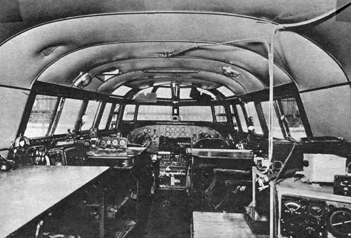
The Gasuden Kōken-ki had an all-metal semi-monocoque fuselage which housed a Kawasaki-built German BMW VIII engine driven by a Sumitomo SW-4 two-bladed metal-shrouded wooden propeller. The wings of the Kōken-ki were carefully designed with the intent of allowing it to operate in thinner air. The cantilever wings were constructed using a Kōken-ki Model 4 aerofoil shape, with about 17.5% thickness. The wingtips however, had a different material which was Kōken-ki Model 11 alloy. This aerofoil only had 4% thickness. The resulting wings had an aspect ratio of 8.7. As the plane was designed with range and endurance in mind. 14 fuel tanks were installed in the wings allowing for 1538 US gallons (5822 L) of fuel. A system was also installed which would allow the fuel to even out in all the tanks in order to maintain center of gravity. The landing gear of the Kōken-ki was retractable in order to reduce drag and once retracted, fairings would cover the landing gear wells. The cockpit was set on the left side of the plane, giving it an asymmetrical design. The Kōken-ki’s windshield could be extended and folded in order to reduce drag. Only when taking off and landing would it be extended. This design was a hindrance for the pilots as they reported poor visibility and control. The Kōken-ki was completely metal, with the exception of fabric covers which were fitted over the control surfaces and wings.
Operators
- Empire of Japan – The Gasuden Kōken-ki was operated solely by Japanese pilots for all the flights it flew.
Gasuden Kōken-ki |
|
| Wingspan | 91 ft 7 in / 27.9 m |
| Length | 49 ft 5 in / 15.1 m |
| Height | 11 ft 9 in / 3.6 m |
| Wing Area | 939.7 ft² / 87.3 m² |
| Wing Loading | 21.6 lb/ft² / 105.9 kg/m² |
| Power Loading | 25.3 lb/hp / 11.5kg/hp |
| Engine | 1x Kawasaki-built BMW VIII 12-cylinder water cooled V-engine (715 hp) |
| Propeller | 1x Sumitomo SW-4 two-bladed metal-shrouded wooden propeller 13 ft 1.5 in / 400 cm |
| Fuel Load | 1538 US gallons / 5822 L |
| Empty Weight | 9314 lb / 4225 kg |
| Loaded Weight | 20317 lb / 9216 kg |
| Maximum Speed | 155 mph / 250 kmh at Sea Level 152 mph / 244 kmh at 6562 ft / 2000 m |
| Cruising Speed | 131 mph / 211 kmh at 6562 ft / 2000 m |
| Range | 8078 mi / 13000 km |
| Maximum Service Ceiling | 11187 ft / 3410 m |
| Crew | 1x Pilot 1x Co-Pilot 1x Flight Engineer |
Gallery


A Series of Youtube Videos on the World Record Attempt:
Sources
Takenaka, K. (2007). Koken Long-range Research-plane., Swopes, B. (2017). 13–15 May 1938., Tupolev ANT-25 Soviet Long Range Record Setter. (n.d.). Fiddler’s Green., Mikesh, R. C., & Abe, S. (1990). Japanese aircraft, 1910-1941. Ann Arbor, MI: Naval Institute., Dyer, E. M. (2015). Japanese Secret Projects: Experimental Aircraft of the IJA and IJN 1922-1945. Ian Allan Publishing. Images: Side Profile Views by Ed Jackson – Artbyedo.com, Other images from http://arawasi-wildeagles.blogspot.com/


